
Related Manuals for WIKA A-AI-2


Summary of Contents for WIKA A-AI-2
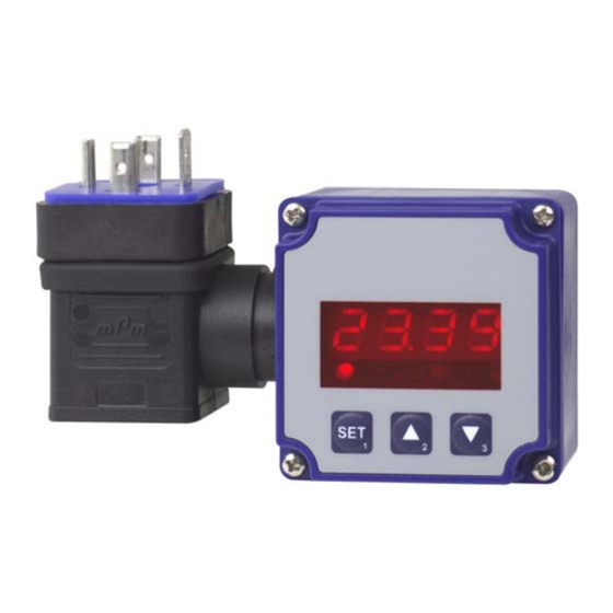
- Page 1 Operating instructions Attachable indicator, model A-AI-2 14014118.01 V2.0 03/2011 • • Attachable indicator, model A-AI-2...
- Page 2 Operating instructions, model A-AI-2 Page 1 - 28 © 2010 WIKA Alexander Wiegand SE & Co. KG All rights reserved. WIKA® is a registered trademark in various countries. Prior to starting any work, read the operating instructions! Keep for later use!
-
Page 3: Table Of Contents
Maintenance ........................22 Cleaning ..........................22 Faults ............................23 Dismounting, return and disposal ................... 24 Demontage .......................... 24 Return..........................24 Disposal ..........................24 10 Appendix ........................... 25 Declarations of conformity can be found online at www.wika.com. WIKA operating instructions, model A-AI-2... -
Page 4: General Information
The general terms and conditions, contained in the sales documentation, shall apply. Subject to technical modifications. Further information: - Internet address: www.wika.de / www.wika.com - Relevant data sheet: AC 80.08 - Application consultant: Tel.: (+49) 9372/132-0 Fax: (+49) 9372/132-406 E-Mail: info@wika.de WIKA operating instructions, model A-AI-2... -
Page 5: Safety
Further important safety instructions can be found in the individual chapters of these operating instructions. 2.1 Intended use The attachable indicator A-AI-2 is used for attaching between a transmitter and the according angular plug. The instrument has been designed and built solely for the intended use described here, and may only be used accordingly. -
Page 6: Personnel Qualification
The skilled electrical personnel have been specifically trained for the work environment they are working in and know the relevant standards and regulations. The skilled electrical personnel must comply with current legal accident prevention regulations. WIKA operating instructions, model A-AI-2... -
Page 7: Special Hazards
Failure to comply with these instructions could result in death or serious injury and material damage. 2.4 Labelling / Safety marks Product label WIKA operating instructions, model A-AI-2... -
Page 8: Specifications
3 Specifications Explanation of symbols Before mounting and commissioning the instrument, ensure you read the operating instructions! CE, Communauté Européenne Instruments bearing this mark comply with the relevant European directives. 3 Specifications Dimensions A-AI-2-1: A-AI-2-S: WIKA operating instructions, model A-AI-2... - Page 9 50.5 x 90 x 39.5 (L x B x T) incl. angular plug Scope of delivery Attachable indicator, mounting screws, profile sealing, operating instructions For further specifications see WIKA data sheet AC 80.08 and the order documentation. WIKA operating instructions, model A-AI-2...
-
Page 10: Design And Function
1st output and the right LED the state of the 2nd output. When leaving our factory the A-AI-2 has been subjected to various inspection tests and is completely calibrated. Before the A-AI-2 can be used, it has to be configured for the customer’s application. -
Page 11: Scope Of Delivery
6 Commissoning, operation 6.1 Electrical connection To connect the A-AI-2 it is simply plugged into an existing transmitter by means of a special adapter for the cubic plug according to DIN 43650. An additional power supply is not necessary , because device takes power directly from measuring current. - Page 12 If the 'Signal/GND'-line in your transmitter is not assigned to contact 2 and if the '-Ub'-line is not assigned to contact 1, please do not forget to adjust the A-AI-2 angle-type plug and the external angle- type plug accordingly. To do so open the A-AI-2 angle-type plug and exchange the wire of contact 1 and contact 2 against the wire of the contact representing the connection in your transmitter.
- Page 13 6 Commissoning, operation Standard assignment of angular plug (A-AI-2-S) contact number wire colour jack blue indicator + indicator - connected black connected yellow connected In the angle-type plug the male contacts 2, 3 and 4 are directly connected 1:1 with the socket. Device is located between the male contact 1 (+) and the jack contact 1 (-).
- Page 14 The same applies to incandescent lamps, whose turn- on-current is also quite high due to their low cold resistance. Connecting to current loop and switching of a relay (A-AI-2-1) combined power supply for measurement section...
-
Page 15: Configuration Of The Indicator
6 Commissoning, operation Switching of a relay (A-AI-2-S) connection as „LowSide“ contactor connection as „HighSide“ contactor 6.2 Configuration of the indicator Please note: The storage of a configuration value will be done by switching to the next configuration value (via button 1). - Page 16 6.2.2 Selection of the output function When pressing button 1 again, the display will show “outP“. (Output) Use button 2 and button 3 (middle or right button) to select the desired output-function. WIKA operating instructions, model A-AI-2...
- Page 17 When pressing button 1 again, the device will display “1.Err“ (error = preferred state of switching function 1). Use button 2 and button 3 to set the desired initial state in case of an error. WIKA operating instructions, model A-AI-2...
-
Page 18: Switching Points / Alarm Boundaries
Depending on the configuration you have made in the „output“ menu you will get different display values. Please follow the specific chapter for further information. 6.3.1 2-point-controller (and 3-point-controller: A-AI-2-S) This chapter describes how to configure the switching points as use the device for a 2-point- resp. 3- point-controller. - Page 19 Min-/Max-Alarm (common or individual) (A-AI-2-S) This chapter describes how to configure the device‘s alarm boundaries for min-/max-alarm-monitoring. This instruction demands that you selected “AL“ (or “AL.2F” for A-AI-2-S) as your desired output function. Press button 1 (when not already done) , the device will display “AL.Hi“. (maximum alarm-...
- Page 20 Now you finished configuring the alarm adjustment of your device. Press button 1 to finish the adjustment and to switch over to display the measuring value. 6.3.3 2-point-controller with min-/max-alarm (A-AI-2-S) This chapter describes how to configure the switching points as use the device for a 2-point-controller with min-/max-alarm.
-
Page 21: Offset And Slope Adjustment
The device displays the following values (without offset- or slope-adjustment): 0.08 at 0.00 bar and 20.02 at 20.00 bar Therefore you calculated: zero point: 0.08 slope: 20.02 – 0.08 = 19.94 deviation: 0.06 (= target-slope – actual-slope = 20.00 - 19.94) WIKA operating instructions, model A-AI-2... -
Page 22: Min-/Max-Value Storage
Before cleaning, correctly disconnect the instrument from the mains. Clean the instrument with a moist cloth. Electrical connections must not come into contact with moisture. For information on returning the instrument see chapter "9.2 Return". WIKA operating instructions, model A-AI-2... -
Page 23: Faults
In this case, contact the manufacturer. If a return is needed, please follow the instructions given in chapter "9.2 Return". WIKA operating instructions, model A-AI-2... -
Page 24: Dismounting, Return And Disposal
9.2 Return WARNING! Strictly observe when shipping the instrument: All instruments delivered to WIKA must be free from any kind of hazardous substances (acids, bases, solutions, etc.). When returning the instrument, use the original packaging or a suitable transport package. -
Page 25: Appendix
10 Appendix 10 Appendix WIKA operating instructions, model A-AI-2... - Page 26 10 Appendix WIKA operating instructions, model A-AI-2...
- Page 27 10 Appendix WIKA operating instructions, model A-AI-2...
- Page 28 WIKA global WIKA subsidiaries worldwide can be found online at www.wika.com. WIKA Alexander Wiegand SE & Co. KG Alexander-Wiegand-Straße 30 63911 Klingenberg • Germany Tel. (+49) 9372/132-0 Fax (+49) 9372/132-406 E-Mail info@wika.de www.wika.de WIKA operating instructions, model A-AI-2...
Need help?
Do you have a question about the A-AI-2 and is the answer not in the manual?
Questions and answers