Table of Contents
Advertisement
Quick Links
Advertisement
Table of Contents

Related Manuals for X2E UPoB

Summary of Contents for X2E UPoB
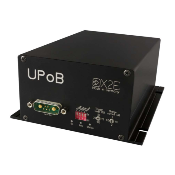
- Page 1 UPoB Universal Power Bridge User Manual Version: 1.6 / April 2019...
- Page 2 This user manual is protected by copyright; all usual rights reserved. Reproduction of this user manual, even in part, is only permitted with the approval of X2E GmbH. Any infringement will result in liability for damages and may result in criminal prosecution.
-
Page 3: Table Of Contents
User Manual UPoB Table of contents Introduction ..................... 4 Intended use .................... 4 Delivery contents ..................4 General safety instructions ..............5 Product overview..................6 Identification ..................... 6 Block diagram ..................7 Connections and controls ................ 8 Installation ..................... 15 Mounting .................... -
Page 4: Introduction
The UPoB is designed for industrial areas and must not be used in residential areas. You may only operate the UPoB within the scope of the technical specifications provided in this user manual. -
Page 5: General Safety Instructions
User Manual UPoB General safety instructions The UPoB is only intended for use by qualified personnel. Read the user manual and espe- cially this chapter thoroughly before operating. CAUTION Electric shock due to damaged components Damages to the UPoB or the power cable can result in electric shock. -
Page 6: Product Overview
User Manual UPoB Product overview Identification The identification plate and the buffer capacity label are located on the bottom side of the UPoB. The identification plate contains information about: device type serial number configuration date of manufacture / last modification Configuration consists of three blocks: ... -
Page 7: Block Diagram
User Manual UPoB Block diagram Normal Bridge mode mode Service Micro- Capacitors controller Charge Trigger Config current level Acoustic signals on mode change The UPoB indicates changes between normal mode and bridge mode by acoustic signals. -
Page 8: Connections And Controls
User Manual UPoB Connections and controls Front view Back view... - Page 9 User Manual UPoB Function KL31 KL30 Switching on/off threshold ≥ 10.9 V: UPoB switches on ≤ 10.0 V: UPoB switches off (if capacitors com- pletely discharged) Normal Bridge Charging threshold mode mode ≥ 11.3 V: capacitors charging ≤ 11.0 V: capacitors stop charging ≤...
- Page 10 Impact of the output switch on other modes In order for the sleep and mode switches to work as described, the output switch needs to be On. Otherwise, the UPoB cannot be woken up from sleep mode if the mode switch is On, for example.
- Page 11 User Manual UPoB Charge current (C) The charge current is included in the maximum input current of the UPoB. Position Charge current left 0.5 A right 1.5 A down Trigger level (D) If the trigger switch (1) is On and the remaining capacitance drops below the configured level, the UPoB sends a trigger signal.
- Page 12 Normal mode: ≈ V drop depends on the output load current (max. 500 mV at 5 A) drop Overcurrent protection The UPoB is equipped with overcurrent protection that reacts within 500 ms if the output load current rises above 5 A.
- Page 13 acknowledge overcurrent event and reactivate voltage output if connected via service interface (I), switch the UPoB into bootloader mode to per- form a firmware update (further information in the corresponding chapter) CAUTION Device damage due to sudden voltage drop Pressing the reset button deactivates the voltage output for a short period of time.
- Page 14 User Manual UPoB Service (I) Use the Micro USB interface to update the firmware. For further information, refer to the cor- responding chapter of this user manual. The pin assignments conform to the USB standard. COM (J) The COM interface consists of: ...
-
Page 15: Installation
Ensure adequate air circulation. Do not cover the UPoB with other objects. Mount the UPoB in such a way that it does not pose a hazard at any time. Connecting DANGER Electric shock due to improper connection Introducing the 4-mm plugs of the supplied power cable into low-voltage sockets can be fatal. - Page 16 Connect the black connector of the power cable to 0 V or ground. Connect the red connector of the power cable to a DC power supply in the specified range. Turn on the power supply. The UPoB indicates its readiness by illuminating the On-LED.
-
Page 17: Firmware Update
User Manual UPoB Firmware update Firmware updates provide bug fixes and new features for the UPoB. For this, you need a PC which meets the following requirements. Supported operating systems: Microsoft® Windows® 7/8/10 (32 Bit or 64 Bit) Hardware requirements: ... -
Page 18: Cleaning
Never open the UPoB. Maintenance and repair must be carried out by X2E personnel only. In case of malfunctions or damages, please contact X2E via e-mail to get information about returning the UPoB: xoraya-return@x2e.de Disposal Within the European Union, the disposal of electrical devices is determined... -
Page 19: Appendix
User Manual UPoB Appendix Technical specifications General Dimensions (H x W x D) 64.4 mm x 105 mm x 164 mm max. 28 V Input voltage bridge mode: max. 10.0 V normal mode: min. 10.3 V bridge mode: max. 11.9 V Output voltage normal mode: max. -
Page 20: Com Breakout Cable
User Manual UPoB COM breakout cable Function COM_RS232_RXD RELAIS_CLOSER RELAIS_OPENER STATUS_CAN_ST_P COM_RS232_TXD 5V_DIGITAL_IO STATUS_CAN_ST_N RS232_GNDIN RELAIS_VCCIN RS232 Function COM_RS232_RXD COM_RS232_TXD RS232_GNDIN Function STATUS_CAN_ST_N STATUS_CAN_ST_P 5 V digital output (Digital_IO) Function RS232_GNDIN 5V_DIGITAL_IO Relay output Colour Function RELAIS_VCCIN yellow RELAIS_OPENER green... -
Page 21: Discharge Times
User Manual UPoB Discharge times The following values apply to a UPoB with 12.5 F capacitance and 12 V input voltage. Accuracy of values Because the stated times are determined empirically, the values might devi- ate under certain circumstances. Output load Bridging time Minilogger V5 Advanced (≈... -
Page 22: Thresholds
User Manual UPoB Thresholds The following graphs show the different thresholds, each dependent on the output load cur- rent I Accuracy of values Because the stated voltages are determined empirically, the values might deviate under certain circumstances. Normal mode to bridge mode: 10.6... - Page 23 User Manual UPoB Switch-on threshold: 11.8 11.6 11.4 11.2 10.8 Charging threshold: 11.8 11.6 11.4 11.2 10.8...
-
Page 24: Status Messages
User Manual UPoB Status messages The COM interface (J) sends the following CAN status messages cyclically. CAN ID Content 0x120 internal states (for example DIP switch positions) 0x121 output load current, output voltage, output power, input voltage 0x122 capacitor voltage, capacitor current, capacitor power,... - Page 26 X2E GmbH Jahnstrasse 2b 76870 Kandel GERMANY Phone +49 7275 9143 100 +49 7275 9143 109 E-Mail info@x2e.de Internet http://www.x2e.de...
Need help?
Do you have a question about the UPoB and is the answer not in the manual?
Questions and answers