Table of Contents
Advertisement
Advertisement
Table of Contents

Subscribe to Our Youtube Channel
Related Manuals for Leica Geosystems DD Series


Summary of Contents for Leica Geosystems DD Series
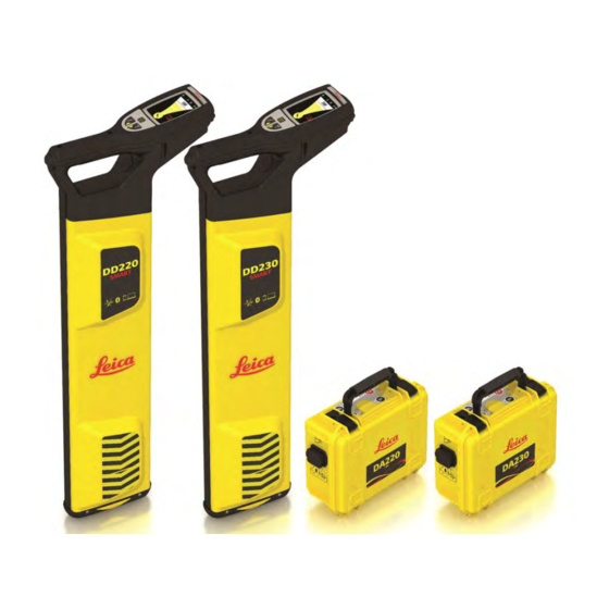
- Page 1 Leica Detection DD Series Locators & Accessories User Manual Version 1.0 English...
- Page 2 Bluetooth SIG, Inc. All other trademarks are the property of their respective owners. Validity of this This manual applies to the Leica Detection DD series locators, DA series trans- manual mitters and Detection accessories. Differences between the models are marked and described.
- Page 3 Service Description myService View the current service status and full service his- tory of your products in Leica Geosystems service centres. Access detailed information on the services performed and download your latest calibration cer- tificates and service reports. mySupport Create new support requests for your products that will be answered by your local Leica Geosystems Support Team.
-
Page 4: Table Of Contents
Table of Contents Safety Directions General Definition of Use Limits of Use Responsibilities Hazards of Use 1.5.1 General 1.5.2 Using the Product with a Signal Transmitter Electromagnetic Compatibility EMC FCC Statement, Applicable in U.S. Description of the System System Information System Components Locator Components Signal Transmitter Components... - Page 5 5.8.2 Locating a Utility Using the Property Plug Connector How to Use the Sondes 5.9.1 General Information Estimating Depth and Current of a Utility Utility Line Depth Sonde Depth Depth Code Information Utility Current Measurement Connectivity Locator Bluetooth Connectivity Locator USB Connectivity Transmitter USB Connectivity Locator Memory and GPS Internal Memory...
-
Page 6: Safety Directions
Safety Directions General Description The following directions enable the person responsible for the product, and the person who actually uses the equipment, to anticipate and avoid operational hazards. The person responsible for the product must ensure that all users understand these directions and adhere to them. -
Page 7: Limits Of Use
Responsibilities Manufacturer of the Leica Geosystems AG, CH-9435 Heerbrugg, hereinafter referred to as Leica product Geosystems, is responsible for supplying the product, including the user man- ual and original accessories, in a safe condition. -
Page 8: Hazards Of Use
• To be familiar with local regulations relating to safety and accident preven- • tion. To inform Leica Geosystems immediately if the product and the application • becomes unsafe. • To ensure that the national laws, regulations and conditions for the opera- tion of the product are respected. - Page 9 WARNING Distraction/loss of attention During dynamic applications, for example stakeout procedures, there is a dan- ger of accidents occurring if the user does not pay attention to the environ- mental conditions around, for example obstacles, excavations or traffic. Precautions: ▶ The person responsible for the product must make all users fully aware of the existing dangers.
- Page 10 CAUTION Inappropriate mechanical influences to batteries During the transport, shipping or disposal of batteries it is possible for inappro- priate mechanical influences to constitute a fire hazard. Precautions: ▶ Before shipping the product or disposing of it, discharge the batteries by running the product until they are flat.
- Page 11 • Precautions: ▶ Do not open the product! ▶ Only Leica Geosystems authorised service centres are entitled to repair these products. WARNING Improper disposal If the product is improperly disposed of, the following can happen: If polymer parts are burnt, poisonous gases are produced which may •...
-
Page 12: Using The Product With A Signal Transmitter
1.5.2 Using the Product with a Signal Transmitter DANGER Clipping a transmitter clamp around a live utility When a transmitter clamp is clipped around a live utility, a hazardous signal might be present on the utility or at the transmitter plug connector, causing you to receive an electric shock. -
Page 13: Electromagnetic Compatibility Emc
Precautions: ▶ Although the product meets the strict regulations and standards which are in force in this respect, Leica Geosystems cannot completely exclude the possibility that other equipment may be disturbed. CAUTION Use of the product with accessories from other manufacturers. For... -
Page 14: Fcc Statement, Applicable In U
Precautions: ▶ Although the product meets the strict regulations and standards which are in force in this respect, Leica Geosystems cannot completely exclude the possibility that other equipment can be disturbed or that humans or ani- mals can be affected. - Page 15 Consult the dealer or an experienced radio/TV technician for help. • CAUTION Changes or modifications not expressly approved by Leica Geosystems for compliance could void the user's authority to operate the equipment. Labelling DD220/DD230 13297_001...
- Page 16 Labelling DA series transmitters 13298_001 Safety Directions...
-
Page 17: Description Of The System
Description of the System System Information General description Locators are used to detect buried conductive utilities that emit an electromag- netic signal. Such a signal is generated as an electrical current passes through the utility. Signal transmitters are used to apply a distinct signal to utilities with the fol- lowing intention: To improve the detection success. -
Page 18: Locator Components
Locator Components Description of components DD220/ DD230 locators Display Locator keyboard USB port Trigger Battery compartment Locator foot (wear part) 13300_001 Signal Transmitter Components Description of transmitter components Accessory compartment Connection socket Battery compartment and USB port Signal transmitter keyboard Speaker Induction arrow 013301_001... - Page 19 Plug the connector into a suitable power 100-240 V source. 12/24 V 14480_001 ☞ The battery pack should be fully charged before use. ☞ Result: The small LED next to the charge jack flashes at a fast rate to indi- cate the wake up process, then flashes at a slower rate to indicate that the battery pack is active and charging.
-
Page 20: Operation Of The Locator
Operation of the Locator Keyboard DD220/DD230 locator keyboard 13302_001 Function key Press and release to change the search mode. Depth Estimation key Press and release to take a depth reading. Menu key Press and hold to display the Locator main menu or to return back to the locate screen. - Page 21 Use the navigation keys to alter the selection. Press the menu key to confirm the selection. Units of Measurement This screen allows you to set up your preferred units of measurement for depth estimation. ☞ To change the units of measurement later on, use the menu option in the Settings menu.
-
Page 22: The Locate Screen
3.3.2 The Locate Screen Description of the screen 13146_001 Status bar Provides information on product and feature selection Numeric Peak Indicator Increases when approaching a utility or sonde and decreases when • moving away. • Provides the highest peak reading when directly over the utility or sonde. -
Page 23: The Depth Estimation Screens
Health Check Health Check passed within the last 24 hours. Health Check process prohibited, e.g. if Health Check is activated in high levels of electrical interference. Scheduled Maintenance Planned maintenance is due for the locator. To adjust the settings, refer to "... - Page 24 Sonde depth This screen indicates the depth of a sonde within a pipe. ☞ Note that the depth is calculated as dis- tance to the sonde within the pipe! 13149_001 Depth out of range This screen indicates that the depth of the utility or sonde is less than the minimum depth range.
- Page 25 Signal out of range This screen indicates that the signal source is too low to provide a depth reading. 14322_001 This screen indicates that the signal source is too high to provide a depth reading. 14323_001 Operation of the Locator...
-
Page 26: Locator Menu
Locator Menu 3.4.1 Access and Navigation Locator main menu The Locator menu is used to display information or to update settings. and submenus A main menu is used to display the main categories. A submenu displays the available options for the selected category. 13155_001 Locator main menu Submenu (Example) -
Page 27: Menu Options
Select this option to close the menu and display the Locate screen. ☞ You can also press and hold the menu key to display the Locate screen. Commonly used menu Icon Description icons This icon indicates an active option or a good condi- tion. - Page 28 Select this option to play a short animation on how to use the loca- tor with the signal transmitter in Induction mode. Select this option to play a short animation on how to use the loca- tor with a sonde. Select this option to play a short animation on how to perform a product Health Check.
- Page 29 Select this option to display the fault code. Indicates a product fault. The fault code is displayed. For a list of fault codes, refer to "10.3 Locator Fault Codes". Indicates that the product condition is good. Select this option to return to the main menu. Submenu ☞...
-
Page 30: Search Modes
Select this option to adjust the Point-of-Interest setting. Available settings: • Select a marker in the desired colour to activate the POI func- tion. Select to turn off the POI function. • Select this option to adjust the display brightness. Select this option to return to the main menu. - Page 31 Search Mode Description Signal Transmitter Used in conjunction with a signal transmitter: mode To improve the detectability of utilities. • • To trace a specific utility. To make a depth or current measurement. • ☞ Keep in mind the following: •...
- Page 32 13195_001 Auto Mode Power Mode Radio Mode Signal Transmitter Mode Sonde Mode Frequency selection Using the locator with a signal transmitter The Signal Transmitter mode features an auto-select option (indicated by ~TX). In Auto mode the locator locks onto the signal transmitters output and updates the Search Mode indicator with the selected frequency.
- Page 33 Action Result The Search Mode indicator Press and release the menu key to displays the selected fre- confirm the selection. quency. 13325_001 ☞ To save the selection throughout the locator’s use, set the Mode Lock setting to ON. Refer to " Submenu Settings" within "3.4.2 Menu Options".
-
Page 34: Operation Of The Transmitter
Operation of the Transmitter Keyboard Transmitter keyboard Power key Power Output key and LED indicators Low Battery LED indicator Connection Mode LED indica- Frequency key and LED indica- tors Mute key 13192_001 Turning On / Turning Off Turning on and off Press the Power key to turn the transmitter on or off. -
Page 35: Applications
Applications How to Pinpoint a Utility Pinpointing process To help you pinpoint a utility, the locator provides a visual and an audible response. 13210_001 Visual response When the locator is positioned directly over a utility and at 90° to it, the Locate screen displays a peak reading. -
Page 36: How To Trace A Utility
☞ The signal strength indicators do not indicate the size, depth or type of a utility. ☞ To ascertain an estimated depth of the utility, use a signal transmitter or a sonde. Refer to "6 Estimating Depth and Current of a Utility". How to Trace a Utility Tracing process Pinpoint a utility by finding the peak reading. - Page 37 Set the locator to Power mode. 13202_001 ☞ Ensure that the locator is held upright and close to the ground. Take care not to swing the locator. 13211_001 Cross the site from left to right until the defined area is covered. 13212_001 Turn through 90 °...
-
Page 38: Using The Transmitter In Induction Mode
☞ To conduct a one-step Sweep Search process or to provide a fast scan for large work areas, the locator can be used in Auto mode. To obtain an improved definition of a detected utility, use the locator in an indi- vidual mode. -
Page 39: Induction Mode: Nulling-Out Method
Select the required power output and frequency. 13280_001 Place the transmitter over the utility with the arrows running in line with the sus- pected direction of the utility. The internal aerial directly induces the tracing signal onto the utility. 13292_001 Set the locator to Signal Transmitter mode and select the required frequency. -
Page 40: Induction Mode: Parallel-Sweep Method
To confirm that the transmitter and the locator are on the same utility, place the signal transmitter upright and directly over the utility. ☞ Either the speaker or the con- nection socket should be on the ground. 13308_001 If the transmitter and the locater are on the same utility, the Numeric Peak Indi- cator on the locator significantly decrea- ses. -
Page 41: Induction Mode: Radial-Sweep Method
Both persons: Start walking parallel to each other. ☞ The tracing signal is induced directly onto the utility and indicated on the locator. 13312_001 In the presence of a detectable utility, the locator emits a tone and the signal strength indicators rise and fall as you pass over the utility. -
Page 42: Using The Transmitter In Connection Mode
Both persons: Start walking parallel to each other, cir- cling the target area. ☞ The tracing signal is induced directly onto the utility and indicated on the locator. 14305_001 In the presence of a detectable utility, the locator emits a tone and the signal strength indicators rise and fall as you pass over the utility. -
Page 43: Direct Connection Mode
☞ An extension cable is available to extend either the red or black cables on the connection cable set. ☞ Reducing the signal output helps to extend the battery life and to reduce the amount of signal applied to adjacent utilities. 5.5.2 Direct Connection Mode Using the transmitter... -
Page 44: Connection Mode: 131 Khz Cable-Wrap Technique
Select the required frequency and power output. To indicate that the tracing signal rea- ches a good level, the Power Output LED indicator and the audible tone change from pulsed to continuous. 13280_001 Set the locator to Signal Transmitter mode and select the required frequency. 13206_001 At a distance of 5 m (16 ft) to the con- nection point, circle around the connec-... - Page 45 Plug the transmitters cable set into the connection socket. 14341_001 Ensuring that no utilities are below, push the Earth Pin into the ground and con- nect the black cable to the Earth Pin. ☞ For more safety, we recom- mend pushing the Earth pin into the ground at an angle of 45 degrees.
-
Page 46: How To Use The Trace Rod
At a distance of 5 m (16 ft) to the con- nection point, circle around the connec- tion point. 14354_001 In the presence of a detectable utility, the locator emits a tone and the signal strength indicators rise and fall as you pass over the utility. -
Page 47: Locating A Utility Using The Trace Rod
Sonde Using Sonde mode, the sonde helps to pinpoint the end point of the trace rod. Line Flexible, glass-fibre sheathed rod, which incorporates copper wires to con- duct the signal. Using Line mode, the rod helps to trace the route of a utility. Connection terminals Used to connect to the signal transmitter. - Page 48 Turn on the transmitter. ☞ Ensure that the Connection Mode LED indicator is on and the battery level of the trans- mitter is adequate. 13279_001 Select the required frequency and power output. To indicate that the tracing signal rea- ches a good level, the Power Output LED indicator and the audible tone change from pulsed to continuous.
- Page 49 Connect the red cable to the positive (+) terminal on the trace rod. Connect the black cable to the negative (-) terminal. 14359_001 Turn on the transmitter. ☞ Ensure that the Connection Mode LED indicator is on and the battery level of the trans- mitter is adequate.
-
Page 50: How To Use The Transmitter Clamps
How to Use the Transmitter Clamps 5.7.1 General Information Description A Transmitter Clamp provides a safe technique of applying a signal to utilities such as telecom cables, electric cables, etc. It is connected to the Transmitter and then clipped around the utility. Supply is not interrupted by the applied signal. -
Page 51: How To Use The Property Plug Connector
Select the required frequency and power output. ☞ For compatible frequencies check the type plate of the transmitter clamp. To indicate that the tracing signal rea- ches a good level, the Power Output LED 13280_001 indicator and the audible tone change from pulsed to continuous. -
Page 52: How To Use The Sondes
Connect the property plug connector to a live mains outlet. ☞ Ensure that the mains connec- tion is switched on and live. 14440_001 Turn on the transmitter. ☞ Ensure that the battery level of the transmitter is adequate. 13268_001 Select the required frequency and power output. - Page 53 so unlike other accessories this does not require a connection to the transmit- ter. The signal pattern transmitted from a sonde is different to that which is radi- ated from a utility and requires tracing in its own unique method. The sonde transmits a peak signal over its main body, with a ghost signal at its front and back.
- Page 54 Retrace your steps and position the loca- tor directly over the peak signal. Move the locator left and right until the highest numeric reading is obtained. This reading indicates the location of the sonde. 14443_001 Applications...
-
Page 55: Estimating Depth And Current Of A Utility
Estimating Depth and Current of a Utility Utility Line Depth Taking a depth ☞ For utility line depth, the locator needs to be used in conjunction reading with a signal transmitter. Refer to "5.4 Using the Transmitter in Induction Mode" and 5.5 Using the Transmitter in Connection Mode. Set the locator to Transmitter mode and select the required frequency. -
Page 56: Sonde Depth
Sonde Depth Taking a depth ☞ For sonde depth, the locators needs to be used in conjunction with a reading sonde. Refer to "5.9 How to Use the Sondes". Set the locator to Sonde mode and select the required frequency. 13208_001 Position the locator directly over and in line with the sonde. -
Page 57: Utility Current Measurement
Utility Current Measurement Current measurement ☞ Model-specific option. to identify utilities ☞ The Current measurement is measured in mA (milliampere) and is dis- played with the utility line depth. Refer to "6.1 Utility Line Depth". Identifying a utility The signal transmitter is used to apply a signal (current) to the utility to be traced. -
Page 58: Connectivity
Connectivity Locator Bluetooth Connectivity Model-specific option: Connecting the locator using The locator is provided with Bluetooth connectivity. Bluetooth Bluetooth status The Bluetooth status is indicated on the status bar of the Locate screen. Refer to " Status bar icons" (within "3.3.2 The Locate Screen"). Colour of Bluetooth Icon Status White... - Page 59 Data Range Example Description Output Value 000 to 999 Model identifier 000000 to 999999 123456 Serial number 0.00 to 9.99 3.01 Software version 00:00 to 23:59 08:30 Time hh:mm Default = 00:00; no RTC fit- 00/00/00 to 01/12/10 Date dd/mm/yy 31/12/99 00 to 12 Number of months until next...
-
Page 60: Locator Usb Connectivity
Locator USB Connectivity Connecting the The locator is provided with a micro USB port and can be connected to a PC for locator using USB one of the following reasons: To update software. • To provide calibration and maintenance support. •... - Page 61 Access to the USB port ☞ The cover of the battery compartment also serves as cover for the USB port. To maintain environmental protection open the cover only in dry conditions. Always close the cover of the battery compartment after use. Unscrew the fastener of the cover.
-
Page 62: Locator Memory And Gps
☞ To transfer records from the worksite, use the transfer app and Blue- tooth connectivity. ☞ Refer to the Leica Geosystems website for the latest information on mobile Apps and analysis software. Internal GPS Record the The internal GPS module is a model-specific option. - Page 63 Select to adjust the Point-of-Interest setting. Select a marker in the desired colour to activate the POI func- • tion. The activated POI status is indicated on the status bar of the Locate screen. Refer to " Status bar icons" (within "3.3.2 The Locate Screen").
-
Page 64: Batteries
• It is normal for the battery to become warm during charging. Using the chargers recommended by Leica Geosystems, it is not possible to charge the battery once the temperature is too high. • For new batteries or batteries that have been stored for a long time (>... - Page 65 Lift the cover of the battery compart- ment and remove the Li-Ion battery pack. 14483_001 Connect the charger plug into the charge jack on the battery pack. 14479_001 Plug the connector into a suitable power 100-240 V source. ☞ The small LED next to the charge jack flashes to indicate that the battery pack is charg- 12/24 V...
- Page 66 Unscrew the fastener of the battery cover. 14472_001 Lift the cover of the battery compart- ment and remove the Li-Ion battery pack. 14475_001 Connect the charger plug into the charge jack on the battery pack. 14479_001 Plug the connector into a suitable power 100-240 V source.
-
Page 67: Functional Checks
10.1 Locator Health Check Checking the function Leica Geosystems accepts no responsibility for maintenance and calibration conducted by unauthorised persons. It is vital to check the status of the unit, its basic functionality and batteries before Calibration Verification is used. -
Page 68: Calibration Verification
Checking the function Leica Geosystems accepts no responsibility for maintenance and calibration conducted by unauthorised persons. It is vital to check the status of the unit, its basic functionality and batteries before Calibration Verification is used. - Page 69 Connect to DX Office Shield via USB. Refer to 7.2 Locator USB Con- nectivity and 7.3 Transmitter USB Connectivity. 016446_001 Purchase and activate Calibration Verification from the CalMaster tab. A user login will be required. Full instructions are provided in DX Office Shield.
-
Page 70: Locator Fault Codes
10.3 Locator Fault Codes Fault codes and If the locator detects a fault, a notification is displayed on the startup screen troubleshooting or within the status bar. To display the locators fault code, access the Alerts menu and select this option: Refer to "Submenu Alerts"... -
Page 71: Functional Check Of The Trace Rod
Perform a Battery check. Observe the Low Battery LED indicator and replace or recharge the batteries if necessary. Checking the The purpose of the following procedure is to verify the performance of the performance transmitter. ☞ Conduct the test away from areas of electromagnetic interference or over buried utilities with a large signal radiating off them. -
Page 72: Functional Check Of The Sonde
Turn on the transmitter. Use the Power Output key on the transmitter to adjust the power output to minimum. The transmitter should emit a constant tone. Disconnect the black cable from the negative (-) terminal. The transmitter should emit a pulsed tone. ☞... - Page 73 Aim the locator foot at the sonde. ☞ At a distance of 2 m/6.56 ft, the signal strength indicators should display a peak reading. ☞ If for any of these tests no output or a significantly different output is displayed, return the sonde for service. Functional Checks...
-
Page 74: Care And Transport
Shipping When transporting the product by rail, air or sea, always use the complete orig- inal Leica Geosystems packaging, container and cardboard box, or its equiva- lent, to protect against shock and vibration. Shipping, transport of When transporting or shipping batteries, the person responsible for the prod-... -
Page 75: Technical Data
Conformity to FCC Part 15 (applicable in US) • national regulations Hereby, Leica Geosystems AG declares that the radio equipment type • DD120/DD130/DD220/DD230 is in compliance with Direc- tive 2014/53/EU and other applicable European Directives. The full text of the EU declaration of conformity is available at the fol- lowing Internet address: http://www.leica-geosystems.com/ce. -
Page 76: Locator Technical Data
Mode Output Audio 85 dBA @ 30 cm Induction mode: Pulsed output with a differing rate for each frequency Connection mode: Low - No output: pulsed output, differing rate for each frequency Good Connection output: constant tone, pitch dependent on power output Battery type 7.4 V Li-Ion pack Typical operating time 3... - Page 77 Mode Frequency Sensitivity @ 1 meter Transmitter 131.072 (131) kHz 32.768 (33) kHz 5uA in 8.192 (8) kHz 100uA 512 Hz (DD230 series 500uA models) 500uA 640 Hz (DD230 series models) Depth estimation Locator DD220 series DD230 series Depth range Line 0.1m to 5m Line 0.1m to 7m Sonde 0.1m to 7m...
- Page 78 Dimensions 290 mm/11.42 inches 93 mm/ 3.66 inches 016453_001 Smart locators Component Value Bluetooth Class 2 BLE dual mode module Bluetooth Classic 2.1 • Bluetooth 4.0 (LE) • Memory 8 GB internal memory Chipset (1): u-blox®GPS • Reciever Type: GPS L1C/A, SBAS L1C/A, QZSS L1C/A, GLONASS L1OF, BeiDou B1 Accuracy (2): Horizontal Position 2.5 m •...
-
Page 79: Conductive Rod Technical Data
Battery pack Description D Series Lithium-Ion Battery pack Type Li-Ion battery pack Input voltage 12 V DC Input current 2.5 A Charge time 5 hours (maximum) at 20°C 12.4 Conductive Rod Technical Data Conductive rod Description Value Typical detection range Both modes, line and sonde: Typical 3.0 m/10 ft Tracing distance... - Page 80 Mode Output Weight 0.15 kg/0.3 lbs Dimensions 80 mm/3.1 Inches 100 mm/3.9 Inches Technical Data...
-
Page 81: Appendix A Time Zone Offsets
Appendix A Time Zone Offsets Time zone offsets Time Zone Offsets... - Page 82 864606-1.0.0en Original text Published in Switzerland © 2018 Leica Geosystems AG, Heerbrugg, Switzerland Leica Geosystems AG Heinrich-Wild-Strasse CH-9435 Heerbrugg Switzerland Phone +41 71 727 31 31 www.leica-geosystems.com...
Need help?
Do you have a question about the DD Series and is the answer not in the manual?
Questions and answers