Table of Contents
Advertisement
Quick Links
User manual
NivuLog Easy V3
User Manual for the GPRS Data Logger
NIVUS GmbH
Im Täle 2
D-75031 Eppingen
Tel.: 0 72 62 / 91 91 - 0
Fax: 0 72 62 / 91 91 - 999
E-Mail: info@nivus.com
Internet: www.nivus.de
NivuLog Easy V3 - Rev. 03 as of 24.10.2018
NivuLog Easy V3
(Original Instruction Manual - German)
Rev. 03 valid from:
Firmware version: 01v007
l
App. version: 02v012
l
Server version: 47.10
l
Hardware version: 3.2
l
1 of 141
Advertisement
Table of Contents

Related Manuals for Nivus NivuLog Easy V3


Summary of Contents for Nivus NivuLog Easy V3
- Page 1 Rev. 03 valid from: Firmware version: 01v007 App. version: 02v012 Server version: 47.10 Hardware version: 3.2 NIVUS GmbH Im Täle 2 D-75031 Eppingen Tel.: 0 72 62 / 91 91 - 0 Fax: 0 72 62 / 91 91 - 999 E-Mail: info@nivus.com...
- Page 2 2 of 141 NivuLog Easy V3 - Rev. 03 as of 24.10.2018...
-
Page 3: Table Of Contents
Chapter 1 Table of contents Chapter 1 Table of contents User Manual for the GPRS Data Logger NivuLog Easy V3 Chapter 1 Table of contents Chapter 2 Safety instructions 2.1 Use of the hazard warnings 2.2 General safety instructions 2.3 Safety and preventative measures for handling GSM/GPRS modems 2.3.1 Safety and precautionary measures for the installation of the GSM/GPRS modem 2.3.2 Safety measures for installing the antenna 2.4 Device labelling... - Page 4 6.1.5 Decay module 6.1.6 Control module 6.1.7 Alarm/trigger module 6.1.8 Record module 6.1.9 Setpoint module 6.1.10 Scale module (outputs) 6.2 Day change 6.3 Functionality of the internal data memory 6.4 Procedure in case of connection aborts 6.5 Aloha transmission mode 6.6 Automatic selection of the GSM network 6.7 Determining the GSM/UMTS/LTE signal strength 6.8 Determining the position data...
- Page 5 8.6.8 Technical details about the energy supply 8.6.8.1 Rechargeable battery pack for NivuLog Easy V3 (NLM0PSU413D+) 8.6.8.2 Rechargeable battery pack for NivuLog Easy V3 (NLM0PSU413D) 8.6.8.3 PSU DC for NivuLog Easy V3 (NLM0PSUDC) 8.6.8.4 PSU AC for NivuLog Easy V3 (NLM0PSUAC) 8.6.8.5 PSU DC+ for NivuLog EASY V3 (- upon request) 8.6.9 Technical details about detecting the failure of the supply voltage...
- Page 6 10.2.1.1.1 Site 10.2.1.1.2 Comments 10.2.1.1.3 Measurement channels 10.2.1.1.3.1 Basis 10.2.1.1.3.2 Config 10.2.1.1.3.3 Alarms 10.2.1.1.3.4 Trigger 10.2.1.1.4 Output channels 10.2.1.1.5 Internal channels 10.2.1.1.5.1 Basis 10.2.1.1.5.2 Alarms 10.2.1.1.5.3 Trigger 10.2.1.1.6 Alarm settings 10.2.1.1.7 Calculated channels 10.2.1.1.7.1 Basis 10.2.1.1.7.2 Calculation 10.2.1.1.7.3 Alarms 10.2.1.1.8 Basic settings 10.2.1.1.9 FTP export settings 10.2.1.2 Default input screen for configuring the site 10.2.1.2.1 Site...
- Page 7 Chapter 1 Table of contents 10.3 Additional measurement channels 10.3.1 Counter readings of the infinite counters Chapter 11 API 11.1 General Chapter 12 Maintenance 12.1 General maintenance 12.2 Replacing the power supply unit 12.2.1 Charging the power supply unit 12.3 Power supply units with integrated energy store Chapter 13 Removal/disposal Chapter 14 Troubleshooting and repair 14.1 General problems...
- Page 8 8 of 141 NivuLog Easy V3 - Rev. 03 as of 24.10.2018...
-
Page 9: Chapter 2 Safety Instructions
Chapter 2 Safety instructions Chapter 2 Safety instructions For the connection, commissioning and operation of the NivuLog Easy V3 , the following information and higher legal regulations of the country (e.g. VDE regulations), such as valid EX regulations as well as the applicable safety and accident prevention regulations for the respective application case must be observed. -
Page 10: Safety And Preventative Measures For Handling Gsm/Gprs Modems
WARNING: Never use this device in areas where the use of wireless equipment is prohibited. The device must not be used in hospitals and/or in the vicinity of medical equipment, such as heart pacemakers or hearing aids, as their functionality could be compromised by the GSM/GPRS modem contained in the device. -
Page 11: Safety And Precautionary Measures For The Installation Of The Gsm/Gprs Modem
Chapter 2 Safety instructions 2.3.1 Safety and precautionary measures for the installation of the GSM/GPRS modem This device must only be installed by a trained technician who applies the recognised installation practices for a radio frequency transmitter including the correct grounding of external antennas. The device must not be operated in hospitals and/or in the vicinity of medical equipment such as heart pacemakers or hearing aids. -
Page 12: Installation Of Spare And Wear Parts
Type plates NivuLog Easy V3 Note: This symbol indicates that the NivuLog Easy V3 is equipped with an integrated SIM chip. Note: These operating instructions are part of the device and must be available for the user at all times. The safety instructions included therein must be observed. WARNING: It is strictly prohibited to disable the safety equipment or modify its mode of operation. -
Page 13: Storage With Inserted Power Supply Unit
Chapter 2 Safety instructions 2.6.2 Storage with inserted power supply unit Activate the transport lock, by setting the "Operation mode" in the "Basic settings" configuration section (see "Basic settings" on page 99) to "transport". You may need to initiate a transmission again to ensure the changed configuration is transmitted to the device. - Page 14 Note: Qualified personnel In the context of these instructions and the warnings on the product itself, individuals responsible for the setup, installation, commissioning and operation of the product must have gained relevant qualifications relating to their activities, including, for example: Training, instruction and authorisation to activate/deactivate, ground and label electric circuits and devices/systems in accordance with the standards of safety engineering.
-
Page 15: Chapter 3 Declaration Of Conformity
Chapter 3 Declaration of conformity Chapter 3 Declaration of conformity NivuLog Easy V3 - Rev. 03 as of 24.10.2018 15 of 141... - Page 16 16 of 141 NivuLog Easy V3 - Rev. 03 as of 24.10.2018...
-
Page 17: Chapter 4 Technical Data
Rechargeable battery pack for NivuLog Easy V3 : 13,2Ah, Li-Ion , integrated overvoltage protection Direct power supply: PSU DC for NivuLog Easy V3 : DC protective circuit PSU DC+ for NivuLog EASY V3 : 900mAh, Li-Po , DC protective circuit PSU AC for NivuLog Easy V3 : 900mAh, Li-Po , 230VAC power supply unit Additional information is provided in "Technical details about the energy supply"... - Page 18 System time Hardware real-time clock with its own buffer battery and automatic time synchronisation with the server. Additional information is provided in "Technical details about the system time" on page Internal sensors Internal housing temperature Measurement range: -20...+60°C Resolution: 0,1°C Humidity in the housing Measurement range: 0...100% rH Resolution: 0,1% rH...
- Page 19 Chapter 4 Technical data USB interface 1 x mini-B USB 2.0 slave for the connection to a PC. The DeviceConfig configuration program must be installed on the PC to enable communication with the NivuLog Easy V3 . Additional information is provided in "Technical details about the USB interface" on page 59.
- Page 20 20 of 141 NivuLog Easy V3 - Rev. 03 as of 24.10.2018...
-
Page 21: Chapter 5 General Specifications
Note: The specifications in this manual are valid as of the versions listed on the front page. Revised versions of this manual are stored in the download center at www.nivus.de. 5.1 Translation For deliveries to countries in the European Economic Area, the manual must be translated into the language of the respective country. -
Page 22: Overview
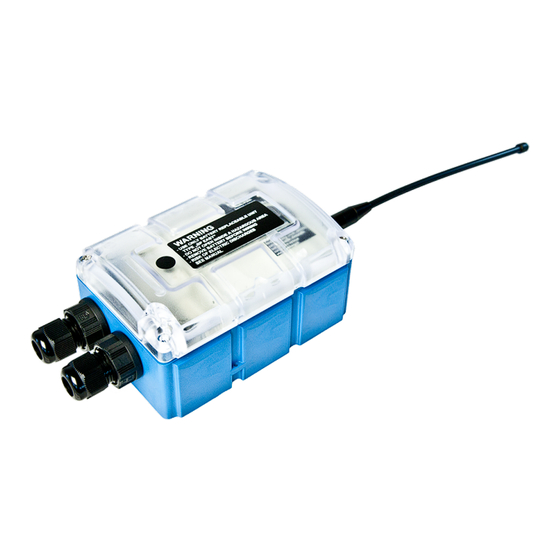
5.4 Overview Note: As the NivuLog Easy V3 is split into several components when delivered, it must be assembled before use (see "Assembling the NivuLog Easy V3 " on page 43). Front of the NivuLog Easy V3 Rear of the NivuLog Easy V3 (view of a device after assembly) (view of a device after assembly) 1 Antenna connector 3 Cable screw connection (cable diameter of 5-... -
Page 23: Block Diagram
Chapter 5 General specifications 5.4.1 Block diagram Block diagram of the NivuLog Easy V3 It is a DC/DC converter with controllable output current. A power supply unit (e.g. Rechargeable battery pack for NivuLog Easy V3 ) that is equipped with a rechargeable battery can thus be charged via the V in-/output. -
Page 24: Intended Use
A Managed Service contract with NIVUS GmbH is required for use of the mobile data transmission (see www.nivus.de). This includes the provisioning of the mobile communications connection via the network of the service provider included in the above-mentioned list. -
Page 25: Chapter 6 Functional Principle
In the graphic below, all of the components that are part of the Device to Web are illustrated in grey. All of the other components must be provided/created by the customer. Functional principle NivuLog Easy V3 with integrated managed service SIM chip (including data transmission) "NivuLog Easy V3 " application script Device to Web server to which the data is transferred Client that accesses the interface of the Device to Web server via the web browser Customer-specific server that provides clients with their own interface. - Page 26 Functions and components provided by Device to Web : NivuLog Easy V3 with installed "NivuLog Easy V3 " application script Portable device with integrated memory and standardised industrial interfaces (UI1-4, PT100/1000, isolated switch contact) for connecting sensors and actuators to the Device to Web server (GPRS)
-
Page 27: Internal Processing Of The Measurement Values
Chapter 6 Functional principle 6.1 Internal processing of the measurement values Diagram of the internal processing of the measurement values 1 Filter to compensate for brief signal fluctuations 7 Monitoring of the alarm limits and trigger levels (see "Filter module" on page 28). The filter (see "Alarm/trigger module"... -
Page 28: Filter Module
Note: Additional explanation on universal inputs that are operated in Digital mode. Measurement channels -> Basis Mode Digital Measurement channels ->Config. Filter time 800ms Input signal Input signal at the universal input Input signal after filter Input signal taking the "filter time" into consideration Logic level The input signal at the universal input is analysed once per second. -
Page 29: Overflow Module
Chapter 6 Functional principle 6.1.2 Overflow module This module monitors the measurement range limits of the raw value. If a universal input was, for example, switched to "4-20mA" mode, a raw value of 2mA will violate the measurement range. The overflow module is only available for the 4 universal inputs in "4-20mA", "0-20mA", "0-2V"... -
Page 30: Decay Module
The following table specifies the relevant parameters for the module: Configuration section Mode Parameter Explanation Measurement channels -> Digital Basis Cnt.Inf. Cnt.Day Cnt.Intrvl. 0-20mA Trimming Provided to adjust the zero point 4-20mA Sensor Specifies the installation height of the sensor 0-2V offset 0-10V... -
Page 31: Control Module
Chapter 6 Functional principle 6.1.6 Control module The control module determines the setpoints for the outputs. The following table specifies the relevant parameters for the module: Configuration section Mode Parameter Explanation Output channels Ext. warmup time Ext. warmup Indicates the amount of time that an output time channel is switched on in "Ext warmup time"... -
Page 32: Alarm/Trigger Module
6.1.7 Alarm/trigger module This module monitors the alarm limits and trigger levels and creates an entry in the alarm list if necessary. The alarm/trigger module is available for inputs (universal inputs and internal channels). All of the parameters of the "Alarms" and "Trigger" tabs of the "Measurement channels" (see "Measurement channels"... -
Page 33: Setpoint Module
Chapter 6 Functional principle 6.1.9 Setpoint module This module uses the setpoints for the outputs entered via the configuration interface of the Device to Web server. The following table specifies the relevant parameters for the module: Configuration section Mode Parameter Explanation Output channels ->... -
Page 34: Day Change
6.2 Day change If an input is operated in Cnt.Day mode, all of the pulses up to the day changing time at midnight based on the time zone selected using the "Time zone" parameter are added up. This parameter is located in the "Basic settings"... -
Page 35: Functionality Of The Internal Data Memory
Chapter 6 Functional principle 6.3 Functionality of the internal data memory Structure Circular buffer Total size 34.944 measurement cycles Number of sectors Sector size 4368 measurement cycles The internal data memory of the NivuLog Easy V3 is designed as a circular buffer with 8 sectors. If the maximum number of data records (34.944 ) is achieved, the sector with the oldest data is deleted fully before new data can be saved in this sector again. -
Page 36: Procedure In Case Of Connection Aborts
6.4 Procedure in case of connection aborts If the connection is terminated, another attempt to establish a connection is made after 2min. for all connections, except for "online" mode. The connection is attempted up to 2 times. An immediate connection attempt is made if the connection is lost in "online" mode. If it is not possible to establish a connection, a new attempt is made every 2min. -
Page 37: Determining The Gsm/Umts/Lte Signal Strength
Chapter 6 Functional principle 6.7 Determining the GSM/UMTS/LTE signal strength The internal update rate of the GSM/UMTS/LTE signal strength is dependent on the type of connection that can be selected via the relevant parameter in the "Basic settings" configuration section (see "Basic settings" on page 99): Interval: Updated during connection establishment Interval &... - Page 38 The following table specifies under which conditions the external SIM card or internal SIM chip is used. The parameters are checked each time the modem is activated."---" indicates a state where it is not possible to establish a connection. External SIM slot External SIM card Correct APN setting SIM used...
-
Page 39: Chapter 7 Storage, Delivery And Transport
Check the shipment immediately upon receipt to ensure it is complete and intact. Immediately report any discovered transport damages to the delivering carrier. Also notify NIVUS GmbH in writing about this without delay. Report any incompleteness of the delivery to the responsible representative or directly to the company headquarters of the manufacturer within two weeks (see "Branch offices"... -
Page 40: Transport
7.4.1 Transporting power supply units WARNING: With the exception of the PSU DC for NivuLog Easy V3 (NLM0PSUDC), the power supply units required to operate the NivuLog Easy V3 are classified as hazardous goods due to the installed rechargeable batteries or battery packs for which the following conditions must be observed during transport. -
Page 41: Return
Support & Service Centre (see "Branch offices" on page 141). The return shipment of the NivuLog Easy V3 must occur in the original packaging and with freight and insurance paid to NIVUS GmbH (see "Branch offices" on page 141). Insufficiently cleared return shipments will otherwise not be accepted! NivuLog Easy V3 - Rev. - Page 42 42 of 141 NivuLog Easy V3 - Rev. 03 as of 24.10.2018...
-
Page 43: Chapter 8 Installation
Chapter 8 Installation Chapter 8 Installation Important note: To prevent any damage to the device, the work described in this section of the instructions must only be performed by qualified personnel. 8.1 Dimensions Dimensions: width and height Dimensions: depth (view of a device after assembly) (view of a device after assembly) 8.2 Assembling the NivuLog Easy V3 Important note:... - Page 44 The NivuLog Easy V3 is split into several components when delivered and must therefore be assembled before use. Components of the NivuLog Easy V3 1 Connector plug (2x 2-pin, 2x 3-pin, 1x 6-pin) 4 NivuLog Easy V3 base unit 2 Power supply unit (not included in scope of 5 4x Delta PT M3.5x25 Torx 15 delivery) 3 2x cable screw connections (cable diameter of 5-...
- Page 45 Chapter 8 Installation 3. Turn the locking nut of the cable screw connection clockwise (left-hand thread) to the stop to increase the distance between the locking nut and engagement hook and thus make it easier to insert the cable screw connection into the hole in the NivuLog Easy V3 base unit. The engagement hook is not symmetrical.
- Page 46 4. First of all thread the connection cables of your sensors, actuators and, if necessary, the supply or charging voltage through one of the two cable screw connections in accordance with the following figure, and then through one of the two holes in the NivuLog Easy V3 base unit. Then connect the cables to the connector plugs as described in chapter "Connecting the sensors, actuators and power supply"...
- Page 47 Chapter 8 Installation 6. Tighten the locking nut by turning it clockwise (left-hand thread). Important note: Ensure that the seal is clean and intact before tightening. Remove any impurities and/or dirt. The manufacturer shall not be liable for any damage to the device caused by leaky or faulty seals.
- Page 48 11. Close the housing cover. The best option is to tighten the four screws crosswise (torque 0,5Nm; At the first screw 0,7Nm because the threads have to be shaped into the base part first.) so that the housing cover is positioned evenly. Important note: Ensure that the seals are clean and intact before closing the housing cover.
-
Page 49: Inserting/Replacing The Sim Card
Chapter 8 Installation 8.3 Inserting/replacing the SIM card Note: The chargeable feature "Unlocking / Device License customers SIM (NLM0LIZENZ02)" must be released to be able to use the SIM slot. Opening the NivuLog Easy V3 1 Delta PT M3.5x25 Torx 15 3 Housing cover 2 Power supply unit 4 Strap to remove the power supply unit... - Page 50 4. Insert the SIM as illustrated in Figure B on the circuit board of the NivuLog Easy V3 . Figure on the circuit board of the NivuLog Easy V3 The following step is only necessary if you want to test the connection to the Device to Web server afterwards.
-
Page 51: Installing The Nivulog Easy V3
Chapter 8 Installation 8.4 Installing the NivuLog Easy V3 Important note: Ensure installation is completed correctly. Comply with existing legal and/or operational directives. Improper handling can cause injuries and/or damage to the devices. The NivuLog Easy V3 must not be operated in the field with the lid open. The pressure compensation must be protected against contamination. -
Page 52: Wall Mounting
8.4.1 Wall mounting For wall mounting the optional "Universal bracket for housing NivuLog Easy 86x126 (NLM0HALEASY)" equipment is required. Step 1 of the wall mounting Step 2 of the wall mounting 1 NivuLog Easy V3 3 Assembly loop (included in the delivery scope of NLM0HALEASY) 2 Delta PT M3.5x8 Torx 15 (included in the delivery 4 Raised head tapping screw 3.5x32 (included in... -
Page 53: Safety Instructions For The Cabling
Chapter 8 Installation 8.5 Safety instructions for the cabling Important note: To avoid any damage, always switch off the voltage supply to the device when performing electrical connections. When connections are made to the NivuLog Easy V3 , the following warnings and information must be observed, in addition to the warnings and information found in the individual chapters on the installation. -
Page 54: Electrical Installation
8.6 Electrical installation Important note: Only qualified personnel should undertake the installation described in this chapter of the operating instructions to avoid any damage to the device. 8.6.1 Connecting the sensors, actuators and power supply Important note: All wiring work must be performed in the de-energised state. Ensure installation is completed correctly. - Page 55 Chapter 8 Installation Assignment of the main terminal block V IN External supply or charging voltage Ground (external supply or charging voltage) Isolated switch contact VEXT Switchable sensor supply (3,3V ) Ground UI 1 Universal input 1 UI 2 Universal input 2 UI 3 Universal input 3 UI 4 Universal input 4 Ground...
- Page 56 6. Connect the antenna (see "Connecting the GSM antenna" on page 57). The antenna is not included in the scope of delivery and must be ordered separately. 7. Insert the power supply unit. The following step is not mandatory. 8. Check whether the connection to the Device to Web has worked correctly (see "Testing communication with the device"...
-
Page 57: Connection Examples
Chapter 8 Installation The following step is only necessary if you are using an external supply or charging voltage. 11. Now switch on the external supply or charging voltage. Note: If you are using a power supply unit without an integrated energy store, the external supply or charging voltage must be switched on before the optional step during which the connection to the server is tested. -
Page 58: Technical Details About The Universal Inputs
3. Connect the antenna extension or antenna directly to the antenna connector of the NivuLog Easy V3 (see "Overview" on page 22). Important note: Do not apply too much force when tightening the antenna. Do not use any tools to tighten the antenna or antenna extension; only tighten it manually. 4. -
Page 59: Technical Details About The Pt100/1000 Interface
DeviceConfig ("DeviceConfig Manual " - upon request). The DeviceConfig configuration program can be downloaded free of charge from the following website: www.nivus.com/produkte/accessories/accessory- software/software-solutions/d2w-deviceconfig Important note: Remove the antenna before connecting the device with the USB interface of a PC. -
Page 60: Technical Details About The Outputs
8.6.6 Technical details about the outputs 8.6.6.1 Switchable sensor supply VOUT Note: The switchable sensor supply output is short-circuit-proof. The output voltage at VOUT can be set to 15V or 23,3V via the "Voltage" parameter located in the input screen for configuring the output channels (see "Output channels" on page 89). Output voltage characteristics subject to the load current for VOUT = 15V Output voltage characteristics subject to the load current for VOUT = 23,3V 60 of 141... -
Page 61: Switchable Sensor Supply Vext
Chapter 8 Installation 8.6.6.2 Switchable sensor supply VEXT Note: The switchable sensor supply output is short-circuit-proof. When using an extension module (e.g. optional GNSS receiver) this output is occupied by the same and is no longer available for the supply of sensors. 3,3V 180mA 8.6.6.3 Isolated switch contact (NO, CC) -
Page 62: Technical Details About The Energy Supply
When an external supply or charging voltage (V IN) is used, the charge control ensures that the rechargeable battery of the power supply unit is charged. The following operating states are possible: Active energy saving mode : The charge control tries to charge the rechargeable battery to 3,8V or to maintain the voltage at this level. -
Page 63: Rechargeable Battery Pack For Nivulog Easy V3 (Nlm0Psu413D+)
Chapter 8 Installation A selection of compatible power supplies is included in the chapter "Charging devices and power supply units" on page 132. The supply voltage input is equipped with a diode to protect against polarity reversal. Depending on the type, the power supply unit contains a rechargeable battery (Rechargeable battery pack for NivuLog Easy V3 , Rechargeable battery pack for NivuLog Easy V3 ), a power supply unit and a rechargeable battery (PSU AC for NivuLog Easy V3 ) or only a protective circuit (PSU DC for NivuLog Easy V3 ). -
Page 64: Psu Dc For Nivulog Easy V3 (Nlm0Psudc)
Protective circuit (V IN) DC-Protection circuit Capacity Type Rechargeable Nominal voltage Operating temperature -20...+60°C Block diagram of the PSU DC for NivuLog Easy V3 Charging temperature Storage temperature 0... +35°C 8.6.8.4 PSU AC for NivuLog Easy V3 (NLM0PSUAC) V IN Not required Protective circuit (V IN) -
Page 65: Technical Details About Detecting The Failure Of The Supply Voltage
Chapter 8 Installation 8.6.9 Technical details about detecting the failure of the supply voltage Power supply units with an integrated rechargeable buffer battery (PSU DC+ for NivuLog EASY V3 and PSU AC for NivuLog Easy V3 ) enable a message to be issued in the event of a supply voltage failure. However, generation of an alarm must be activated via the relevant parameter in the "Basic settings"... - Page 66 Output voltage of the power supply unit PSU OUT Threshold at which the malfunction message is issued: 9V notify Threshold for switching to supply via the rechargeable buffer battery: backup PSU DC+ for NivuLog EASY V3 : 6V to 7V (depending on the state of charge of the rechargeable buffer battery) PSU AC for NivuLog Easy V3 : 17V Time delay for issuing the malfunction message –...
-
Page 67: Technical Details About The System Time
Chapter 8 Installation 8.6.10 Technical details about the system time The NivuLog Easy V3 is equipped with a hardware real-time clock that has its own buffer battery with an expected service life of >10 years. The system time continues to run even if the power supply unit is removed. This means that following recommissioning, valid time stamps for the measurement and log data can be generated immediately. - Page 68 68 of 141 NivuLog Easy V3 - Rev. 03 as of 24.10.2018...
-
Page 69: Chapter 9 Initial Start-Up
Read this manual carefully and completely in order to ensure the proper functioning of the NivuLog Easy V3 . Contact NIVUS GmbH (see "Branch offices" on page 141) if anything is unclear or if you encounter difficulties with regard to installation, connection or configuration. - Page 70 5. Establish a connection. Insert the power supply unit for this purpose. It is designed in such a way that it cannot be inserted incorrectly. Details on this are provided in the chapter "Assembling the NivuLog Easy V3 " on page 43. The status LED should then start to flicker (see "2-colour status LED" on page 73), indicating that a connection is being established.
-
Page 71: Testing Communication With The Device
71). 9.4 Testing communication with the device 1. Use the "NivuLog Easy V3" application template to create a new site/application for operation on the Device to Web server (see "Device to Web Server Manual" - upon request). - Page 72 8. Check the incoming data in the Aloha data window of the Device to Web server, which can be accessed by clicking on the speech bubble with the "Aloha" inscription (see "Device to Web Server Manual" - upon request). Particular attention must be paid to the "GSM" and "SOC" measurement values.
-
Page 73: Chapter 10 User Interfaces
Chapter 10 User interfaces Chapter 10 User interfaces The configuration of the NivuLog Easy V3 is carried out via the web interface on the Device to Web server (see "User interface on the Device to Web server" on page 75), which your responsible sales partner will provide to you. - Page 74 Error/status codes Blink code Colour Description Solution/cause Transport lock (transmission OFF, If the Aloha transmission mode is measurement OFF) initiated via the button, the NivuLog Easy V3 resumes operation in accordance with the configuration (transmission ON, measurement ON). Green Last connection OK Last transmission faulty Try again later Network block/no matching provider...
-
Page 75: User Interface On The Device To Web Server
Chapter 10 User interfaces 10.2 User interface on the Device to Web server 10.2.1 Site configuration Note: Depending on the respective user level, some of the configuration fields mentioned in the following sub- chapters may be hidden. In this case, please contact the administrator of the Device to Web server. Click on the name of the site in the list of sites to open the specific input screen for configuring the site. - Page 76 Mode Basic settings for the measurement channel Universal inputs Measurement channel deactivated Digital Invert Inverts the input signal (digital mode & counter modes) Cnt.Inf. Pulse Metered measurand of a pulse in the "Imp. unit" Pulse unit String that specifies the measurement unit in which the pulses are supplied Pulse factor Factor with which the metered measurand of a...
- Page 77 Chapter 10 User interfaces Universal inputs 0-20 mA Start of the measurement range in the measurement unit (analogue 100% End of the measurement range in the modes 1/2) measurement unit Trimming Provided to adjust the zero point (see "Additional explanation on the zero point adjustment and installation height of the sensor"...
- Page 78 Universal inputs 0-10V Start of the measurement range in the measurement unit (analogue 100% End of the measurement range in the modes 2/2) measurement unit Trimming Provided to adjust the zero point Sensor Offs. Specifies the installation height of the sensor Unit String that is used as a measurement unit by all of the server display elements [0-8 characters] Decimal...
- Page 79 Chapter 10 User interfaces Note: Additional explanation on the zero point adjustment and installation height of the sensor Assumption: Measurement range of the 4-20mA pressure sensor 0-5m Installation situation of the pressure sensor 1 Installation height: 15cm 3 Output value of the sensor: 6cm 2 Pressure sensor 4 Measured fill level: 20cm Required configuration...
-
Page 80: Config
10.2.1.1.3.2 Config Universal inputs Digital Filter time Time in [ms] during which the signal must remain constant to (digital mode) initiate a level change. Used to suppress brief faults (debouncing). Decay Temporal function in the measurement cycle Decay deactivated At least x consecutive measurement values must be "High"... - Page 81 Chapter 10 User interfaces Universal inputs Cnt.Inf. Filter time Time in [ms] during which the signal must remain constant to initiate a level change. Used to suppress brief faults (Counter modes) (debouncing). Last set Value to which the counter was set during the last change via counter the "Set value"...
- Page 82 Note: Additional explanation regarding the difference between "Cnt.Day" and "Cnt.Intrvl." Basic setting Record interval 4 min. Recorded value red line Measurement cycle 1 min. Measurement value blue line "Cnt.Intrvl." mode: The pulses are added up and reset "Cnt.Day" mode: All of the pulses up to the reset time every time a measurement value is generated.
- Page 83 Chapter 10 User interfaces Universal inputs 0-20 mA Filter time Time in [ms] during which the analogue signal is averaged for signal smoothing. Used to suppress signal noise (also (0-20mA mode) see "Output channels" on page 89). Decay Temporal function in the measurement cycle Decay deactivated The minimum of the last x measurement values is recorded.
- Page 84 Universal inputs 4-20mA Filter time Time in [ms] during which the analogue signal is averaged for signal smoothing. Used to suppress signal noise (also (4-20mA mode) see "Output channels" on page 89). Decay Temporal function in the measurement cycle Decay deactivated The minimum of the last x measurement values is recorded.
- Page 85 Chapter 10 User interfaces Universal inputs 0-2V Filter time Time in [ms] during which the analogue signal is averaged for signal smoothing. Used to suppress signal noise (also (0-2V mode) see "Output channels" on page 89). Decay Temporal function in the measurement cycle Decay deactivated The minimum of the last x measurement values is recorded.
- Page 86 Universal inputs 0-10V Filter time Time in [ms] during which the analogue signal is averaged for signal smoothing. Used to suppress signal noise (also (0-10V mode) see "Output channels" on page 89). Decay Temporal function in the measurement cycle Decay deactivated The minimum of the last x measurement values is recorded.
-
Page 87: Alarms
Chapter 10 User interfaces 10.2.1.1.3.3 Alarms Note: In the event of an alarm or a warning, an entry is always created in the alarm list and an immediate transmission is initiated. "Digital" mode A "high" at the universal input triggers a "warning". A "high"... - Page 88 "Digital" Event trigger RI Execute recording immediately mode Initiate transmission Edges Selection of the edge at which the trigger should be initiated rising The rising edge initiates the trigger. falling The falling edge initiates the trigger. both Both edges initiate the trigger. Level trigger ON Activate online mode The alternative record interval should be used.
-
Page 89: Output Channels
Chapter 10 User interfaces All other Level trigger ON Activate online mode modes The alternative record interval should be used. (2/2) If this checkbox has been selected, the setpoint output is only released on the switchable sensor supply output VOUT if the trigger is active. - Page 90 Mode Basic setting for the output channel Note: Note that the power consumption increases significantly when "Freq" mode is activated. When using a rechargeable battery pack (e.g. Rechargeable battery pack for NivuLog Easy V3 ) the running time to be reached might thus be reduced to 1/6. Output channel deactivated Ext.
- Page 91 Chapter 10 User interfaces Note: Example to explain the filter time in conjunction with the ext. warmup time Basic setting Record interval 5min. Measurement cycle 1min. Output channels Ext. warmup time 1sec. Measurement channels - Filter time 500ms >Config. Output on the device Sensor supply Explanation: The sensor supply is always activated 1sec before expiry of the measurement cycle.
- Page 92 Note: Example for explaining the release of the setpoint at the output via the trigger Basic settings Measurement cycle 1min. Measurement channels -> Selected Trigger Threshold Greater or equal Hyst % Output channels Mode Digital Invert Setpoint Trigger not active Green line Trigger active Red line...
-
Page 93: Internal Channels
Chapter 10 User interfaces 10.2.1.1.5 Internal channels 10.2.1.1.5.1 Basis Title GSM Freely selectable channel title for the GSM level Unit String that is used as a measurement unit by all of the server display elements [0-8 characters] Title voltage Freely selectable channel title for the external supply or charging voltage (V IN) Unit String that is used as a measurement unit by all of the server display elements [0-8 characters]... -
Page 94: Trigger
10.2.1.1.5.3 Trigger The following two type of triggers are differentiated: Event trigger (RI, XM) The relevant operation (e.g. initiate transmission) is only executed once when the trigger event occurs. Level trigger (ON, RA, OS, O3, OD, QX) The relevant operation (e.g. activate online mode) is executed as long as the trigger is active. Event trigger RI Execute recording immediately Initiate transmission... -
Page 95: Alarm Settings
Chapter 10 User interfaces 10.2.1.1.6 Alarm settings Acknowledgement Standard The global server setting is used to determine whether alarms must be acknowledged automatically or manually (siehe "Device to Web Server Manual" - upon request) Automatic Alarms are acknowledged automatically as soon as all of the messages have been sent. -
Page 96: Basis
10.2.1.1.7.1 Basis Title 1-5 Freely selectable channel title for the calculated channels [0-16 characters] Mode Possible calculation modes for the calculated channels Calculated channel deactivated Table Defines the lower scale end of the pointer instruments Defines the upper scale end of the pointer instruments Unit String that is used as a measurement unit by all of the server display elements [0-16 characters]. -
Page 97: Calculation
Chapter 10 User interfaces Shift element down Shift element up 10.2.1.1.7.2 Calculation Calculated channel deactivated Table Source Selection of the channel from which the input data is used Opens the screen for entering the values table (the table rows are interpolated linearly, values outside of the defined table are extrapolated linearly.) Digital Source... -
Page 98: Alarms
Note: Additional explanation: Delta mode Assumption: The source channel contains the counter reading of an infinite counter in m . The calculated channel 1 should contain the flow rate in m /s and calculated channel 2 should contain the flow rate in l/h. Required configuration Parameter Value channel 1 Value channel 2... -
Page 99: Basic Settings
Chapter 10 User interfaces 10.2.1.1.8 Basic settings Connection type Selection of the connection type Interval The device connects in the transmission cycle. Interval & wakeup The device connects to the server in the transmission cycle and can be placed into Aloha transmission mode via the server. - Page 100 Transmission time Selection of whether a connection to the server should be established every day at a firmly defined time No additional transmissions The adjacent option can be used to determine the time at which the device establishes a connection to the server regardless of the transmission cycle.
-
Page 101: Ftp Export Settings
Chapter 10 User interfaces Daylight saving time Configuration for automatic time adjustment Standard The configuration for the time adjustment is adopted by the global server setting (see "Device to Web Server Manual" - upon request). Automatic time adjustment deactivated Predefined setting for the American area Predefined setting for the European area Position cycle Position update interval (00:00 positioning is completed with every connection) -
Page 102: Default Input Screen For Configuring The Site
10.2.1.2 Default input screen for configuring the site 10.2.1.2.1 Site Customer Specifies to which customer the site is assigned. symbol Assign site to another customer Name Site designation (not relevant for the device or data assignment) [2-50 characters] Device S/N Serial number of the device that is linked to the site (device assignment!) Application template Name of the application template from which the site was created Tags... -
Page 103: Basis
Chapter 10 User interfaces 10.2.1.2.4.1 Basis Title 1-5 Freely selectable channel title for the calculated channels [0-16 characters] Mode Possible calculation modes for the calculated channels Calculated channel deactivated Table Defines the lower scale end of the pointer instruments Defines the upper scale end of the pointer instruments Unit String that is used as a measurement unit by all of the server display elements [0-16 characters]. -
Page 104: Calculation
Shift element down Shift element up 10.2.1.2.4.2 Calculation Calculated channel deactivated Table Source Selection of the channel from which the input data is used Opens the screen for entering the values table (the table rows are interpolated linearly, values outside of the defined table are extrapolated linearly.) Digital Source Selection of the channel from which the input data is used... -
Page 105: Alarms
Chapter 10 User interfaces Note: Additional explanation: Delta mode Assumption: The source channel contains the counter reading of an infinite counter in m . The calculated channel 1 should contain the flow rate in m /s and calculated channel 2 should contain the flow rate in l/h. Required configuration Parameter Value channel 1 Value channel 2... -
Page 106: Basic Settings
10.2.1.2.5 Basic settings Time zone Regional settings (not relevant for raw measurement data as this is stored in UTC) Daylight saving time Configuration for automatic time adjustment Standard The configuration for the time adjustment is adopted by the global server setting. Automatic time adjustment deactivated Predefined setting for the American area Predefined setting for the European area... -
Page 107: Device Configuration
Chapter 10 User interfaces 10.2.2 Device configuration Note: Several of the configuration fields in the following sub chapters may possibly be hidden depending on the respective user level. In this case, contact the Device to Web server administrator. You can reach the input screen for configuring the device by clicking on the serial number in the site list (see "Device to Web Server Manual"... -
Page 108: Gprs
Script sync Productive If the application script installed on the device and saved on the server do not match, the application script saved on the server is loaded in to the device. Development (sync) The application script on the device and server are synchronised. - Page 109 Chapter 10 User interfaces channel (see "Measurement channels" on page 75). If "Cnt.Inf." mode is active, the measurement value contains the current counter reading of the infinite counter. In return, the measurement channel that is assigned to the relevant universal input as standard is set to NaN. Switching the measurement channels is necessary as the data type of the standard measurement channels is f32 (32Bit floating point) and thus does not cover the necessary value range or provide the necessary level of accuracy.
- Page 110 110 of 141 NivuLog Easy V3 - Rev. 03 as of 24.10.2018...
-
Page 111: Chapter 11 Api
Chapter 11 API Chapter 11 API Important note: The relevant licences are required on the Device to Web server to use the API (Application Programming Interface). For future information contact your responsible sales partner. 11.1 General The API is provided to export data from and import data to the Device to Web server. However, this is not just limited to the pure measurement data but includes all of the data provided by Device to Web server (e.g. - Page 112 112 of 141 NivuLog Easy V3 - Rev. 03 as of 24.10.2018...
-
Page 113: Chapter 12 Maintenance
Chapter 12 Maintenance Chapter 12 Maintenance Important note: To prevent any damage to the device, the work described in this section of the instructions must only be performed by qualified personnel. The device must be deenergised before any maintenance, cleaning and/or repair work. 12.1 General maintenance Regularly check the NivuLog Easy V3 for mechanical damage. - Page 114 3. Remove the four screws that secure the housing cover. Now open the NivuLog Easy V3 . 4. Remove the power supply unit from the NivuLog Easy V3 and replace the existing power supply unit with a new one. Use the strap provided to remove the power supply unit. Note: Ensure that power supply units, especially ones with integrated energy store (rechargeable battery or battery), are disposed of in line with environmental requirements.
- Page 115 Chapter 12 Maintenance 7. Check that the housing cover is positioned correctly on all sides and that no foreign materials have been trapped between the housing and housing cover. Important note: The manufacturer is not liable for any damage that is caused by housing covers that are not closed correctly.
-
Page 116: Charging The Power Supply Unit
12.2.1 Charging the power supply unit All power supply units with an integrated and rechargeable energy store are delivered with a maximum charge of 30% in accordance with applicable transport regulations. If you use an external charging voltage (V IN) during operation, the power supply unit is constantly charged by the charge controller integrated in the NivuLog Easy V3 . -
Page 117: Power Supply Units With Integrated Energy Store
Chapter 12 Maintenance The charging process starts as soon as the power supply unit is inserted in the charger. If the status LED on the charger flashes red once every 5 seconds, the power supply unit inserted in the charger does not contain a rechargeable energy store. - Page 118 118 of 141 NivuLog Easy V3 - Rev. 03 as of 24.10.2018...
-
Page 119: Chapter 13 Removal/Disposal
Chapter 13 Removal/disposal Chapter 13 Removal/disposal Incorrect disposal can cause environmental hazards. Dispose of the device components and packaging material in accordance with the locally valid environmental regulations for electronic products. 1. Disconnect any charging voltage that has been used. 2. - Page 120 120 of 141 NivuLog Easy V3 - Rev. 03 as of 24.10.2018...
-
Page 121: Chapter 14 Troubleshooting And Repair
Chapter 14 Troubleshooting and repair Chapter 14 Troubleshooting and repair 14.1 General problems Problem Cause/solution Device does not Check the cable connections (see "Connecting the sensors, actuators and respond (status LED power supply" on page 54) The capacity of the energy store in the power supply unit is depleted. always off). - Page 122 Problem Cause/solution The alarm state was not Check the alarm settings of the measurement channel The connection was aborted during the transmission, which is indicated by transmitted although the a time-out entry in the connection list (see "Device to Web Server Manual" - data is present.
-
Page 123: Log Entries And Error Codes
Chapter 14 Troubleshooting and repair 14.2 Log entries and error codes Log entry Parameter Description Code Plain text Code Plain text 1000 POWER ON Restart following a power failure Watchdog reset (e.g. because of an exception) Reset was initiated by the device itself (e.g. in event of firmware update) Restart for another reason. - Page 124 Log entry Parameter Description Code Plain text Code Plain text 1039 UV MODEM The rechargeable battery or battery voltage once RECOVER again suffices to guarantee a stable connection. This is either achieved by replacing the rechargeable battery or battery pack or by ensuring that the charge control has charged the battery sufficiently.
- Page 125 Chapter 14 Troubleshooting and repair Log entry Parameter Description Code Plain text Code Plain text 1282 ZLIB Internal error STREAMFINISH Contact the manufacturer if the device log includes this error several times (see "Branch offices" on page 141). 1300 USB CONNECTED --- USB connection to a PC established 1310 USB USB connection was terminated...
-
Page 126: Modem Error
Log entry Parameter Description Code Plain text Code Plain text 2600 MODULE DEBUG Reserved for extensions 2799 3000 SCRIPT ERROR Internal system error Contact the manufacturer if the device log contains this error with the same parameter code 3099 several times (see "Branch offices" on page 141). - Page 127 Chapter 14 Troubleshooting and repair Log entry Parameter Description Code Plain text Code Plain text 1200 NETLOCK ERROR -966 Error when selecting the network. Check whether the device is in the coverage area. External SIM card: Contact the provider that supplied the SIM card.
-
Page 128: Module-Specific Critical Errors
14.2.2 Module-specific critical errors Log entry Parameter Description Code Plain text Code Plain text 2002 MODULE ERROR There was a memory overflow in one of the two (002) infinite counters. 2003 MODULE ERROR Internal error (003) Contact the manufacturer if the device log includes this error several times (see "Branch offices"... -
Page 129: Evaluating The Device Log Using Deviceconfig
Chapter 14 Troubleshooting and repair 14.3.2 Evaluating the device log using DeviceConfig The DeviceConfig program can be used to read all of the stored log entries, including those that have not yet been transferred to the Device to Web server, directly from the NivuLog Easy V3 via the USB interface. A more detailed description about the evaluation of the device log using DeviceConfig is included in the user manual for the DeviceConfig ("DeviceConfig Manual "... - Page 130 130 of 141 NivuLog Easy V3 - Rev. 03 as of 24.10.2018...
-
Page 131: Chapter 15 Spare Parts And Accessories
Chapter 15 Spare parts and accessories Chapter 15 Spare parts and accessories 15.1 Chargeable features Description Quantity Order number Unlocking / Device License customers SIM NLM0LIZENZ02 Unlocking of integrated temperature input NLM0V3TEMP 15.2 Assembly sets Description Quantity Order no. Universal bracket for housing NivuLog Easy 86x126 NLM0HALEASY 15.3 Antennas Description... -
Page 132: Power Supply Units
Rechargeable battery pack for NivuLog Easy V3 (Li-Ion ; 13,2Ah; NLM0PSU413D -20...+60°C operating, 0...+40°C charging temperature) Direct supply PSU DC for NivuLog Easy V3 (-20...+60°C operating temperature) NLM0PSUDC PSU AC for NivuLog Easy V3 : 230VAC power supply unit with Backup NLM0PSUAC batterie (Li-Po ; 900mAh; -20...+60°C operating, 0...+40°C charging temperature) PSU DC+ for NivuLog EASY V3 (Li-Po ;... -
Page 133: Chapter 16 Document History
Chapter 16 Document history Chapter 16 Document history Rev. Date Changes 17.08.2016 First version 13.12.2016 Chapter "Assembling the NivuLog Easy V3 " on page 43 Note added: power supply units with an integrated rechargeable energy store must be fully charged before being used for the first time. Chapter "Technical details about the energy supply"... - Page 134 Rev. Date Changes 24.10.2018 Chapter "Intended use" on page 24 Information on the manufacturer's liability disclaimer regarding the loss of data has (2/5) (2/5) been updated Chapter "Device labelling" on page 11 Explanation of the third type plate added; the plate specifies the chargeable features released at the time of delivery Chapter "Storage of the product"...
- Page 135 Chapter 16 Document history Rev. Date Changes 24.10.2018 Chapter "Installing the NivuLog Easy V3 " on page 51 Note added indicating that the pressure compensation must be protected against (3/5) (3/5) contamination Chapter "Connecting the sensors, actuators and power supply" on page 54 Explanation of the extension interface added Note added indicating the VEXT is no longer available to supply the sensors if an extension mode is used...
- Page 136 Rev. Date Changes 24.10.2018 Chapter "Testing communication with the device" on page 71 Instructions for inserting the USB B Mini Conslot removed as it is already installed (4/5) (4/5) at the time of delivery "Test mode" has been replaced with "Aloha transmission mode" Chapter "Solenoid switch"...
- Page 137 Chapter 16 Document history Rev. Date Changes 24.10.2018 Chapter "Internal channels" on page 93 Note added indicating that in the event of an alarm or a warning, an entry is always (5/5) (5/5) created in the alarm list and an immediate transmission is initiated. There are now two separate parameters: one for the hysteresis for the all-clear in the event of alarm/warning and one hysteresis for revoking the trigger.
- Page 138 138 of 141 NivuLog Easy V3 - Rev. 03 as of 24.10.2018...
-
Page 139: Chapter 17 Glossary
Chapter 17 Glossary Chapter 17 Glossary Aloha Connection mode that is specially designed for commissioning. The device maintains a connection to the server for a configurable amount of time and takes a measurement every 3 seconds. During this process, only the internal measurement values (GSM level, voltages, etc.) and the values from the universal inputs (if available) are generated. - Page 140 140 of 141 NivuLog Easy V3 - Rev. 03 as of 24.10.2018...
-
Page 141: Chapter 18 Branch Offices
Phone: +44 (0)8445 3328 83 www.nivus.de nivusUK@nivus.com www.nivus.com NIVUS AG Burgstrasse 28 NIVUS Middle East (FZE) 8750 Glarus, Switzerland Building Q 1-1 ap. 055 Phone: +41 (0)55 6452066 P.O. Box: 9217 Fax: +41 (0)55 6452014 Sharjah Airport International swiss@nivus.com Free Zone www.nivus.de...
Need help?
Do you have a question about the NivuLog Easy V3 and is the answer not in the manual?
Questions and answers