Table of Contents
Advertisement
Advertisement
Table of Contents

Related Manuals for Designs for Vision LED DayLite NanoCam HDi DVI-LEDSC

Summary of Contents for Designs for Vision LED DayLite NanoCam HDi DVI-LEDSC
- Page 1 LED DayLite ® NanoCam HDi ™ UIDE Model: DVI-LEDSC Ver. 1.18 (En)
- Page 2 ATE OF SSUE 1-18-2018 LED D ® ™ UIDE...
- Page 3 . LED D ® HD ™ ESIGNS FOR ISION The Designs for Vision LED DayLite® HDi Headlights provide ™ bright, portable light to the surgical environment. They are designed to be comfortable yet functional. The headlights are made to clip onto a wide variety of frames and/or headsets.
- Page 4 Always examine the unit and accessories for damage before commencing use. Damaged accessories must not be used and must be replaced. Use original Designs for Vision, Inc. parts and accessories only. The use of unapproved parts may void the warranty.
- Page 5 This equipment and accessories do not contain serviceable parts. All repairs need to be conducted by Designs for Vision, Inc. service personnel Do not let liquids enter openings or ports. Do not immerse parts in solutions. Allowing liquids to enter openings or ports may void warranty.
- Page 6 Remove battery from power pack if this device is not in use and will be stored for some time. Maintain storage at environmental conditions listed below Improper use of battery may cause them to get hot, ignite or explode. Always follow all safety precautions listed in this manual Never make changes or modifications to the battery pack...
- Page 7 PECIFICATIONS POWER REQUIREMENTS Battery Power : Designs for Vision, Inc. 7.4VDC, 3400mAh ® LED DayLite 18650 Li-Ion Battery ® ™ Model Number: DVI-LEDSC For Charging : Cell-Con Charger Input : 100-240VAC, 50/60 Hz, Model P/N: 2240 .35A Output : 8.4 VDC, 1.3A max USB Power (NanoCam HD ™...
- Page 8 ENVIRONMENTAL OPERATING CONDITIONS TEMPERATURE: C to 40 RELATIVE HUMIDITY: 30% to 75% ATMOSPHERIC PRESSURE: 700 to 1060 hPa OVERCURRENT PROTECTION Firmware Controlled Protection RECOMMENDED SYSTEM REQUIREMENTS (NanoCam ™ Operating System: Windows 7 or better Available Memory: 2GB Preferred Available HD Space: 20GB Preferred Minimum CPU Speed: 1.7GHz or Better...
- Page 9 Continuous MODE OF OPERATION NO APPLIED PARTS PROTECTION FROM SHOCK: METHODS OF Not Intended to be Sterilized STERILIZATION Not Intended for Oxygen Rich OXYGEN RICH Environments ENVIRONMENT 8,851,709; 8,215,791; 7,690,806 PATENTS: HDi™ Technology Patent Pending External charger provided with an approved detachable power supply cord which can be easily and safely remove from supply mains Dimensions and weight measured without the micro-video lens or locking ring LED D...
-
Page 10: Table Of Contents
ONTENTS Device Description ................11 Directions for Use ................13 LED DayLite® HDi™ Initial Setup and charging ......13 Holster Operation ...............15 Using the Power Link Feature .............17 Understanding the Status Indicator ...........17 Replacing the Battery ..............19 Using the NanoCam HD/HDi .............20 ™ Inspection and Preventative Maintenance ........29 Description of Various Symbols ............31 Replacement Parts ................32... -
Page 11: Device Description
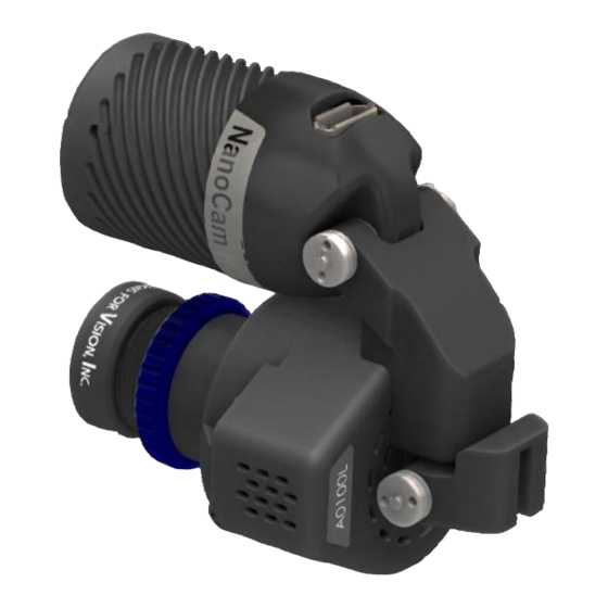
EVICE ESCRIPTION The NanoCam HDi records high resolution 1080p video over ™ USB. The attached headlight is designed to provide even color corrected illumination to enhance the images captured. The light has a correlated color temperature of 5800˚K at an intensity of up to 38,000 lux. - Page 12 Accessories include: Two Holsters w/Belt Clips Power Link Cable Hex Drivers Cable Wrap Kit Operation Manual Registration Card T-Mount Bracket Carrying Case USB Extension Cables 2.5x/3.5x/WA µVideo Lens System USB Foot Pedal USB Drive w/Camera Software Focusing Card LED D ®...
-
Page 13: Directions For Use
IRECTIONS FOR LED D ® ™ NITIAL ETUP AND CHARGING Remove the components from the shipping container, checking that all parts on the packing NOTE: The list have been received. Carefully batteries need to receive a full remove the headlight, power pack(s), charge before desktop charger and charger cord... - Page 14 Plug the power cord into the charger and connect the desktop charger to the AC outlet. NOTE: International adapters are available through Designs for Vision; refer to the list on page The power button light will start pulsing to indicate the unit is in “Smart Charge”...
-
Page 15: Holster Operation
OLSTER PERATION In addition to the holsters, Ratcheting Belt Clips have been included to allow for a full 360° rotation of the unit, even while it is attached to you. To place the belt clip on to the holster, simply slide it up over the raised circular ratchet disk until an audible ‘click’... - Page 16 Squeeze the clip together to open. Arrow A (Fig. 4) shows where to press. The power pack can rotate to your desired position. Each increment is followed by an audible click. To remove the power pack from the clip, depress the button on the top of the belt clip while pulling up on the power pack, which is shown by arrow B (Fig.
-
Page 17: Using The Power Link Feature
SING THE OWER EATURE In the event that you require additional run-time, we have supplied a Power Link Cable which will allow you effectively double the number of hours your headlight will last. Turn both power packs on and simply connect two power pack units together, as shown (Fig. - Page 18 OLID REEN ULLY HARGED ATTERY OLID ULSING ATTERY LINK ENERAL RROR LEASE CONTACT ESIGNS FOR ISION FOR FURTHER ASSISTANCE LINK ATTERY PENT LEASE CONTACT ESIGNS FOR ISION FOR FURTHER ASSISTANCE NOTE: A spent battery should not be used. Contact Designs for Vision Inc.
-
Page 19: Replacing The Battery
(Fig. 7). Unplug the black connector on the NOTE: If the battery is battery on the inside of the unit. Note: installed Replace with Designs for Vision, Inc. improperly, the unit will not battery only. Using... -
Page 20: Using The Nanocam Hd/Hdi
install in the proper orientation. Plug the battery into the connector then place the battery in the pack. Make sure all wires are tucked into the compartment. Replace door and tighten screw. NOTE: You will need to fully charge the battery before the fuel gauge will read properly. - Page 21 1. M ™ OUNTING NSERTING ABLES Mount the NanoCam HDi to your frames or headset using ™ the supplied T-Mount. Attach the HDi Headlight (Fig. 12) to ™ the camera as shown. Plug the small connector of the headlight cable into the top of the headlight. Plug the large connector of the cable into the headlight connector on the power pack.
- Page 22 2. A ™ LIGNING WITH IELD OF While wearing the camera on your frame, look through your surgical telescopes (loupes) at the provided focusing card. NOTE: It is helpful to have the card placed on a flat surface with the video monitor directly in front of you. The card should be placed in the center of your field of view.
- Page 23 EADLIGHT ONNECTOR EADLIGHT AMERA ICRO OUNT IDEO YSTEM YSTEM . 13 ORMING NOTE: Make sure to keep your head still when shifting your view from the surgical telescopes (loupes) to the video monitor. Carefully remove your frame making sure to not shift the camera.
- Page 24 camera with your telescopes. Place the camera back on your face. NOTE: Gently Pull up and down on your camera to confirm that it is locked in place. 3. F ™ OCUSING Next, you will need to focus the micro-video lens system. Your NanoCam HDi comes with three magnifications of micro- ™...
- Page 25 . 14 system clockwise decreases the focal length of the camera. Rotating the micro-video lens system counter-clockwise increases the focal length of the camera. While holding the micro-video lens system with one hand, use your other hand to turn the lens system lock ring counter- clockwise until it locks the micro-video lens system into place.
- Page 26 focused, the camera will have the same magnification and depth of field as what you see through your surgical telescopes (loupes). 4. A ™ LIGNING THE EADLIGHT WITH The final adjustment is the headlight. Get the hex screwdriver included with your NanoCam HDi .
- Page 27 Your NanoCam HDi is available with a shielded USB foot ™ pedal to allow for hands free operation. Once connected to a PC with the Designs for Vision, Inc. software already ® installed, the foot pedal will help to control the camera functions.
- Page 28 . 16 UDIO ECORD NAPSHOT TART NOTE: For foot pedal to function, NanoCam HDi software has ™ to be the active screen on your PC. The default settings for the foot pedal are Record Start/Stop, Audio Mute and Snapshot (Fig. 16). When you press Audio Mute, you will hear an audible alert.
-
Page 29: Inspection And Preventative Maintenance
When you press Record Start/Stop, you will also hear an audible alert. Video will be recording at full resolution and frame rate. Pressing Record Start/Stop again will stop the recording. When you press the Snapshot button, you will hear an audible sound. This indicates that a photo/bookmark has been made. - Page 30 Do not immerse parts in solutions. Using solutions other than recommended may void warranty. Allowing liquids to enter openings or ports may void warranty. • Wipe cables with plastic-safe cleaners, if necessary. Do not allow cleaners to get onto the cable connectors as it may cause the electrical terminals to corrode •...
-
Page 31: Description Of Various Symbols
ESCRIPTION OF ARIOUS YMBOLS ATTENTION / CAUTION CAUTION: HOT SURFACE INDICATES CONFORMITY WITH MDD 93/42/EEC ANNEX VII INDICATES WHERE THE UNIT CAN BE TURNED ON AND OFF INDICATES BATTERY STATE OF CHARGE INDICATES WHERE THE UNIT CAN BE CHARGED READ ACCOMPANYING DOCUMENTS WASTE ELECTRICAL AND ELECTRONIC EQUIPMENT (WEEE) DIRECTIVE SYMBOL LED D... -
Page 32: Replacement Parts
ELECTRICAL SHOCK HAZARD EQUIPMENT CLASS TEMPERATURE LIMITS HUMIDITY LIMITS ATMOSPHERIC PRESSURE LIMITS EPLACEMENT ARTS ESCRIPTION UMBER NanoCam HDi 4003-0000-0003 ™ NanoCam HDi Headlight 4003-3000-0001 ™ Battery 4912-0000-1018 Li-Ion Battery Charger 4912-0000-2019 United States Plug & Cord Set 4706-0000-0038 European Plug & Cord Set 4706-0000-0030 Australian Plug &... -
Page 33: Electromagnetic Information
Reorient or relocate the receiving device ▪ Increase the separation between the equipment ▪ ▪ Consult Designs for Vision, Inc. for help Table 201 – Guidance and Manufacturer’s Declaration – Emissions All Equipment and Systems Guidance and Manufacturer’s Declaration – Emissions ®... - Page 34 Electromagnetic Environment- Emissions Test Compliance Guidance ® The LED DayLite uses RF ™ energy only for its internal function. Therefore, its RF RF Emissions Group 1, Class A emissions are very low and are CISPR 11 not likely to cause any interference in nearby electronic equipment.
- Page 35 Table 202 – Guidance and Manufacturer’s Declaration – Immunity All Equipment and Systems Guidance and Manufacturer’s Declaration – Immunity The LED DayLite is intended for use in the electromagnetic ® ™ environment specified below. The customer or user of the LED DayLite ®...
- Page 36 Voltage 0% U : for 0% U : for Mains power Dips/Dropout 0.5 Cycle 0.5 Cycle quality should be that of a typical At 0˚, 45˚, 90˚, At 0˚, 45˚, commercial or 61000-4-11 135˚, 180˚, 90˚, 135˚, hospital 225˚, 270˚, 180˚, 225˚, environment.
- Page 37 Table 204 – Guidance and Manufacturer’s Declaration – Emissions Equipment and Systems that are NOT Life-Supporting Guidance and Manufacturer’s Declaration – Emissions The LED DayLite is intended for use in the electromagnetic ® ™ environment specified below. The customer or user of the LED DayLite ®...
- Page 38 Table 206 – Recommended Separation Distances between portable and mobile RF Communications equipment and the LED DayLite® HDi™ Equipment and Systems that are NOT Life-Supporting Recommended Separations Distances for the LED DayLite ® ™ The LED DayLite is intended for use in the electromagnetic ®...
- Page 39 GSM 1800; 1720 CDMA 1900; Pulse 1700 - GSM 1900; 1845 Modulation 1990 DECT; LTE 217 Hz Band 1, 3, 4, 1970 25; UMTS Bluetooth, WLAN, Pulse 2400 - 802.11 2450 Modulation 2570 b/g/n, RFID 217 Hz 2450, LTE Band 7 5240 Pulse 5100 -...
- Page 40 Use of this equipment adjacent to or stacked with ARNING other equipment should be avoided because it could result in improper operation. If such use is necessary, this equipment and the other equipment should be observed to verify that they are operating normally. Use of accessories, transducers and cables other ARNING than those specified or provided by the manufacturer of this...
- Page 41 The EMISSIONS characteristics of this equipment make it suitable for use in industrial areas and hospitals (CISPR 11 class A). If it is used in a residential environment (for which CISPR 11 class B is normally required) this equipment might offer adequate protection...
-
Page 42: Warranty
ARRANTY The The NanoCam HDi is warranted against imperfections ™ and defects in materials and workmanship for three years. The power pack is warranted for two years. The internal batteries, charger, and cables are warranted for one year. The power pack electronics are warranted for two years. LED D ®... - Page 43 4000 Veterans Memorial Hwy Bohemia, NY 11716 Toll Free 800/345-4009 • Fax 631/585-3404 • Web Site: www.DesignsForVision.com • P/N: 0075-8511-0071 E-mail: info@dvimail.com...
Need help?
Do you have a question about the LED DayLite NanoCam HDi DVI-LEDSC and is the answer not in the manual?
Questions and answers