Advertisement
Advertisement
Table of Contents

Related Manuals for Veethree VeeCAN 128


Summary of Contents for Veethree VeeCAN 128
- Page 1 VeeCAN 128 VeeCAN Veethree Engine Monitor ™...
- Page 2 Introduction Thank you for choosing the VeeCAN 128 display. ™ These pages provide a brief introduction to the VeeCAN 128 display, ™ but more importantly the recommended installation instructions. This display comes installed with Veethree Engine Monitor (VEM) software which displays J1939-compatible engine/transmission data. Please read through the guide before use.
-
Page 3: Table Of Contents
CONTENTS Section Page 1 ....The VeeCAN 128 Platform..........4 ™ 2 ....VeeCAN 128 Connection Data......... 5 ™ 3 ....Typical J1939 Wiring Topology......... 6 4 ....VeeCAN 128 Installation........... 7 ™ 5 ....Maintenance and Troubleshooting........9 6 ....Home Screen............... 10 7 .... -
Page 4: The Veecan 128 Platform
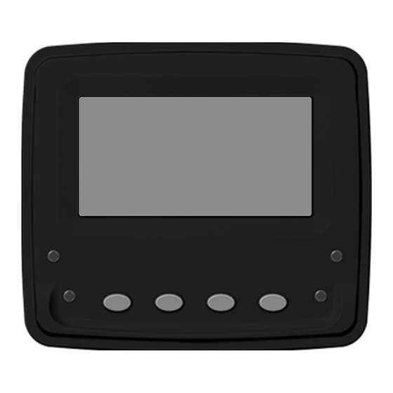
1. The VeeCAN 128 Platform The VeeCAN 128 display is a compact platform that is large enough ™ to support monitoring and diagnostic data available on the latest generation of electronically controlled systems. The display offers 4 soft keys, 128 x 64 pixel display area, and 4 warning lights to signify engine fault/failure. -
Page 5: Veecan 128 Connection Data
2. VeeCAN 128 Connection Data The VeeCAN 128 interfaces to data via the Deutsch DT04-6P connector ™ on the rear of the display - wired as shown (see pin out diagram). Ground and power (10 - 32VDC). Supply should be protected by 500mA-rated circuit breaker/fuse. -
Page 6: Typical J1939 Wiring Topology
120 ohm resistors at each end. In addition, all stubs should not exceed 1m in length, and a maximum of 30 nodes. Termination Resistor (120 ohm) Backbone (Max length 40m) VeeCAN 128 Display Stub (Max length 1m) Engine and/or Node (30 max) -
Page 7: Veecan 128 Installation
Leave sufficient cable so that the unit may be removed for servicing. Cut a 2 inch (51 mm) hole. Screw the studs into the rear case. Place the VeeCAN 128 in position, use the mounting bracket and ™ thumb nuts to secure the units. The thumb nuts should only be hand tight. - Page 8 Unit mounting method...
-
Page 9: Maintenance And Troubleshooting
No regular maintenance is required, except for cleaning the VeeCAN ™ 128 lens as required, using a soft, damp cloth. Do not use abrasive materials or solvents. If you are experiencing operating problems with VeeCAN 128 please ™ refer to the following diagnostics: Ensure connections to unit are correct. -
Page 10: Home Screen
6. Home Screen There are 3 main user screens accessed via the first three keys. The keys have icons to represent the screen view types, as follows. Key 1 is a quad gauge view, pressing Key 1 repeatedly will cycle through available quad screens (4 screen max). - Page 11 The information that is displayed on the quad, dual, and single screens can be selected and arranged for better viewing by the operator. Once in the desired gauge view (quad, dual, single), press and hold the Key for that view. Quad Screen Dual Screen SingleScreen...
-
Page 12: Alarms Screen
7. Alarms Screen When an alarm condition exists, the information is sent from the engine and/or transmission, the information will be displayed via alarm icons, LEDs, and internal alarm buzzer (and external if connected). Check Engine - Alarm will sound along with Orange LEDs. Stop Engine - Alarm will sound along with Red LEDs. -
Page 13: Main Menu
8. Main Menu To access the Main Menu of the VeeCAN 128 display, press and hold ™ Key 4 when at the home screen. Once in the menu use Key 1 and 2 to navigate selections, Key 3 to enter selection, and Key 4 to go back. -
Page 14: Glossary
9. Glossary Controller Area Network (also referred to as CAN bus); serial communication protocol for automotive use VeeCAN 128 Intelligent CAN-compatible LCD display module ™ Veethree Engine Monitor J1939 SAE engine data protocol using CAN 2.0B Liquid Crystal Display Soft keys Push-button keys whose function changes according to use. -
Page 15: Important Safety Information
Veethree operates a policy of continuous improvement. Veethree reserves the right to alter and improve the VeeCAN 128 displays and ™ software without prior notice. - Page 16 Veethree Electronics and Marine LLC 2050 47th Terrace East, Bradenton , Florida 34203 USA www.v3instruments.com | 1-941-538-7775 | Fax: 1-941-755-1222 VeeCAN 128 ™ EETHREE NGINE ONITOR 70617 Rev. 1...
Need help?
Do you have a question about the VeeCAN 128 and is the answer not in the manual?
Questions and answers