
Related Manuals for Vetus V-docker

Summary of Contents for Vetus V-docker
- Page 1 NEDERLANDS ENGLISH Operation manual and installation instructions Bedieningshandleiding en installatie instructies V-docker Copyright © 2017 Vetus b.v. Schiedam Holland 020702.01...
-
Page 2: Table Of Contents
........Raadpleeg de eigenaarshandleiding voor Bediening, Onderhoud, Consult the owner’s manual for Operation, Maintenance, Trouble Storingen en Technische gegevens.’ shooting and Technical data. Preliminary vetus® Installation Manual V-docker 020702.01... -
Page 3: Veiligheid
Wij adviseren dat alle onderdelen van dit systeem worden Zorg er voor dat de eigenaar van het schip over deze geïnstalleerd door een professionele installateur. handleiding kan beschikken. Preliminary vetus® Installation Manual V-docker 020702.01... -
Page 4: Tijdens Het Varen
Een hoog motortoerental is eerder bereikt dan verwacht. Een hoog motortoerental is eerder bereikt dan verwacht. Duw de joystick naar voren om Trek de joystick naar achteren het motortoerental te verlagen. om het motortoerental te ver- lagen. Preliminary vetus® Installation Manual V-docker 020702.01... -
Page 5: Bediening Gashendel, 'Opwarmen
100 omw/min. Het maximale motortoerental dat ingesteld kan worden is ca. halfgas. De normale bediening wordt hervat door eenmaal op de knop op de joystick te drukken. Stationair toerental Preliminary vetus® Installation Manual V-docker 020702.01... -
Page 6: Tijdens Het Afmeren 'Docking Mode
Maar met de joystick in de uiterste stand vooruit (of achteruit) zal de motor onmiddellijk naar vol gas gaan. Dit is om de boot snel te kun- nen stoppen tijdens het afmeren. Preliminary vetus® Installation Manual V-docker 020702.01... - Page 7 Zolang de knop bovenop de joystick wordt ingedrukt, blijft de Dit voorkomt de kans om in en uit schakelen tijdens het gebruik van voortstuwingsmotor op hetzelfde toerental en de keerkoppeling de joystick. in vooruit (of achteruit). Preliminary vetus® Installation Manual V-docker 020702.01...
-
Page 8: Installatie
• Draai het paneel met de onderzijde naar boven. • Verwijder de rubberen dop. • Door het gat zie je een rij DIP schakelaars. • De DIP schakelaars moeten worden geconfigureerd zoals aange- geven in de tekeningen. Preliminary vetus® Installation Manual V-docker 020702.01... -
Page 9: Paneel 1 Of Paneel 2 Bij 2 Panelen
Plaats de servomotor eenheid zo dicht mogelijk bij de voortstu- wingsmotor in de motorruimte. eT op Vermijd plaatsing waar de servomotor eenheid wordt blootgesteld Installeer de servomotor eenheid nog niet. aan hoge temperaturen (motoruitlaat) of trilling (op de motor zelf ). Preliminary vetus® Installation Manual V-docker 020702.01... -
Page 10: Trek-Drukkabel
Trek-drukkabel Aansluiting op de gashefboom en de keerkoppeling wordt gedaan De eerste stap is de installatie van de servomotor, deze kan worden d.m.v. Vetus trek-drukkabels type LF. uitgevoerd voordat er elektrische aansluitingen worden gemaakt en initiële instelprocedure is uitgevoerd. De kabels moeten zo kort mogelijk gehouden worden, terwijl de buigs- traal nooit minder mag zijn dan de minimale straal van 165 mm. -
Page 11: Boeg- Of Hekschroef
Tunnel boegschroef • Installeer eerst de boegschroef volgens de installatiehandleiding. Om een boegschroef aan te sluiten op de CAN-bus van het V-Docker- systeem is een aansluitkast nodig. • Installeer de aansluitkast dichtbij de boegschroef. • Verwijder de originele besturingsbedrading van de boegschroef en vervang deze met de bedrading die bij de aansluitkast wordt geleverd. -
Page 12: Elektrische Verbindingen
Elk van de 3 aansluitingen van de hubs is gelijk in functie, daarom is de volgorde van het insteken op de hub niet belangrijk. Systeem met één bedieningspaneel (1) BEDIENINGS- AANSLUIT- PANEEL KAST TERMINATOR STROOM KABELS BOEGSCHROEF BOEGSCHROEF SERVOMOTOR Preliminary vetus® Installation Manual V-docker 020702.01... -
Page 13: Instelprocedure
• Schakel de stroom in op zowel de CAN bus als de servomotor. • Zet de DIP-schakelaar S4 in de stand ON. S4 in positie ON SETUP SETUP S4 in positie OFF RUN (Normale operatie) Preliminary vetus® Installation Manual V-docker 020702.01... -
Page 14: Neutraalstand Keerkoppeling
DIP schakelaar instelling: • Gebruik de drukknop om maximaal gas te geven. MAXIMAAL TOERENTAL MOTOR aarschuWing De uiterste standen van de kabeleinden mogen nooit voorbij de me- chanische grenzen van de keerkoppeling of de gashendel komen. Preliminary vetus® Installation Manual V-docker 020702.01... - Page 15 • Monteer de kabeluiteinden op de gashendel en de keerkoppe- ling. • Plaats de rubberen dop terug en monteer het deksel op de actu- ator. • Test de werking van het systeem, raadpleeg de gebruikershand- leiding hiervoor. Preliminary vetus® Installation Manual V-docker 020702.01...
- Page 16 Preliminary vetus® Installation Manual V-docker 020702.01...
-
Page 17: Safety
Introduction other panel will be switched off. 2 sec. This manual give guidelines for operating ans fitting the Vetus V- locker. Make sure that the batteries are supplying the correct voltage during Taking over control to another panel can be carried out only with the use The system in maintenance-free. -
Page 18: Cruising Mode
A high engine speed it reached sooner as expected. Push the joystick forwards to Pull the joystick backwards to decrease the engine speed decrease the engine speed Preliminary vetus® Installation Manual V-docker 020702.01... -
Page 19: Operation Throttle Only, 'Warming Up
100 RPM. The maximum engine speed which can be set is approx. half throttle. Normal operation is resumed by pressing the push button on the joystick once. Idling speed Preliminary vetus® Installation Manual V-docker 020702.01... -
Page 20: Docking Mode
But with the joystick in the extreme position forward (or reverse) the engine will go to full throttle immediately. This is to stop the boat quickly during docking. Preliminary vetus® Installation Manual V-docker 020702.01... - Page 21 As long as the button on top of the joystick is pressed the propul- This prevents the risk of switching in and out of gear while moving sion engine will remain at the same speed and the gearbox in for- the joystick around. ward (or reverse). Preliminary vetus® Installation Manual V-docker 020702.01...
-
Page 22: Installation
• Turn the panel upside down. • Remove the rubber plug. • Look through the hole to see a row of DIP switches. • The DIP switches must be configured as shown in the drawings. Preliminary vetus® Installation Manual V-docker 020702.01... -
Page 23: Panel 1 Or Panel 2 Of Two Panels
Avoid a location where the actuator unit may be exposed to exces- sive heat (engine exhaust) or vibrations (on the engine itself ). Do not install the actuator unit to the selected location yet! Preliminary vetus® Installation Manual V-docker 020702.01... -
Page 24: Push-Pull Cables
Connection to the throttle lever and the gearbox lever is to be done The first step, installation on the actuator side, can be done prior to by means of Vetus push-pull cables type LF. electrical connections are made and the initial set-up procedure is carried out. -
Page 25: Thrusters
Tunnel thruster • First install the tunnel thruster as per installation manual. To connect a tunnel thruster to the CAN-bus of the V-Docker system a control box is required. • Install this control box close to the tunnel thruster. -
Page 26: Electrical Connections
Any of the 3 connections of the hubs are equal in function, therefore the sequence of the plugs on the hub is not important. System with one control (1) control panel CONTROL I/O BOX PANEL TERMINATOR POWER SUPPLY THRUSTER THRUSTER ACTUATOR Preliminary vetus® Installation Manual V-docker 020702.01... -
Page 27: Setting Procedure
• Switch on the power to both the CAN bus and the actuator. • Set DIP switch S4 in position ON. S4 in position ON SETUP SETUP S4 in position OFF RUN (Normal operation) Preliminary vetus® Installation Manual V-docker 020702.01... -
Page 28: Neutral Gear
11.4 Engine Maximum Speed DIP switch setting: • Use the push button switches to align maximum throttle position. ENGINE MAXIMUM SPEED arning Do not allow cable end positions beyond mechanical limits of gearbox or throttle lever. Preliminary vetus® Installation Manual V-docker 020702.01... - Page 29 4 5 6 • Install cable ends to throttle and gearbox lever. • Re-install rubber plug and install cover on actuator unit. • Test the functioning of the system, consult the owner’s manual how to do. Preliminary vetus® Installation Manual V-docker 020702.01...
- Page 30 Preliminary vetus® Installation Manual V-docker 020702.01...
-
Page 31: Hoofdafmetingen
” ) 172 x 69 ( 6 ” x 2 ” ) ” ) I/O Box Control box thruster 356 (14”) 187 ( 7 ” ) ø 5.5 ( ” ) ” ) Actuator Preliminary vetus® Installation Manual V-docker 020702.01... -
Page 32: Aansluitschema's
System with one (1) control panel and en tunnel boeg- en hekschroef tunnel type bow and stern thruster 15/54 12 V 12 V MOTOR AUX IN AUX OUT MOTOR AUX IN AUX OUT S.LOCK POWER 12 V Preliminary vetus® Installation Manual V-docker 020702.01... - Page 33 Startmotor Starter Relais (Beveiliging tegen starten wanneer keerkoppeling is Relay (Start-in-gear protection) ingeschakeld) Accu Battery Aansluiten van intrekbare boeg of hek schroef Connection of retractable bow or stern thruster AUX OUT AUX IN MOTOR Preliminary vetus® Installation Manual V-docker 020702.01...
- Page 34 Aansluiten tweede bedieningspaneel Connection of second control panel 15/54 15/54 Preliminary vetus® Installation Manual V-docker 020702.01...
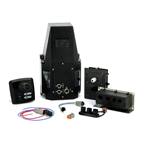
- Page 35 Bedieningspaneel Control panel I/O Aansluitkast I/O Box CAN-Aansluitkabel CAN-Connection cable CAN-Terminator CAN-Terminator CAN-Verloopkabel CAN-Adaptor cable Contactslot Key switch Preliminary vetus® Installation Manual V-docker 020702.01...
- Page 36 Alternator 10 Aansluitkast boegschroef Connection box thruster Kleurcode bedrading: Wiring colour code: #1 Rood (+) Red (+) #2 Geel Yellow #3 Bruin Brown #4 Groen Green #5 Blauw (-) Blue (-) #6 Wit White Preliminary vetus® Installation Manual V-docker 020702.01...
- Page 37 55 kgf 60 kgf 12/24 V DC 75 kgf 12/24 V DC Preliminary vetus® Installation Manual V-docker 020702.01...
- Page 38 Preliminary vetus® Installation Manual V-docker 020702.01...
- Page 39 Preliminary vetus® Installation Manual V-docker 020702.01...
- Page 40 FOKKERSTRAAT 571 - 3125 BD SCHIEDAM - HOLLAND b.v. TEL.: +31 0(0)88 4884700 - sales@vetus.nl - www.vetus.com Printed in the Netherlands 020702.01 2017-10...
Need help?
Do you have a question about the V-docker and is the answer not in the manual?
Questions and answers