
Related Manuals for Label ETERNA 90

Summary of Contents for Label ETERNA 90
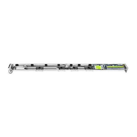
- Page 1 ETERNA 90 Automation for automatic sliding doors TRANSLATION OF THE ORIGINAL INSTRUCTIONS ETERNA 90 - GB - Rel. 1 - 01/20 9 - CD0709EN...
-
Page 2: Table Of Contents
GENERAL SAFETY WARNINGS page GENERAL SAFETY OBLIGATIONS DESCRIPTION OF THE MODELS TECHNICAL SPECIFICATIONS OF THE ETERNA 90 AUTOMATION MECHANICAL COMPONENTS OF THE ETERNA 90 SLIDING DOOR AUTOMATION ETERNA 90 AUTOMATION COMPONENTS TECHNICAL DRAWINGS - COMPONENT ARRANGEMENT COVERING CASING BELT TIGHTENING ADJUSTMENT... - Page 3 ELECTRONIC SECTION 11) ELECTRIC ARRANGEMENTS 12) ELECTRIC CONNECTIONS 13) ET-DSEL DIGITAL PROGRAMMER - PURPOSE AND CONNECTIONS 14) COMMISSIONING OF THE AUTOMATION (INITIAL SET-UP) 14.1) FIRST START OF THE ET-DSEL DIGITAL PROGRAMMER 14.2) SERIAL COMMUNICATION SETTINGS 14.3) INITIAL SET-UP 14.4) FUNCTIONAL TESTING 14.5) INPUT DIAGNOSTICS 15) BATTERY-POWERED EMERGENCY OPENING DEVICE ET-BAT90 16) STAND BY SWITCHING...
-
Page 4: General Safety Warnings
This product is designed and built exclusively for the purpose described in this documentation. Any other use that is not specifically indicated could adversely impact the condition of the product and the safety of people. Label accepts no responsibility for incorrect product installation and usage, as well as for any damage caused by changes made without its prior consent. -
Page 5: Description Of The Models
The choice of the model depends on the type of door to be automated (single- or double-leaf sliding door). All ETERNA 90 automation models can be equipped with the battery for emergency opening and with the electric lock. The automation must be installed in indoor environments. -
Page 6: Eterna 90 Automation Components
3 - ETERNA 90 AUTOMATION COMPONENTS side panel pair upper belt coupling ET-LOGIC-B electronic control unit lower belt coupling ET-MOT 90 motor unit with encoder cable gland fall prevention cables return pulley double wheel carriage mechanical limit switch driving belt... -
Page 7: Technical Drawings - Component Arrangement
4 - TECHNICAL DRAWINGS - COMPONENT ARRANGEMENT DOUBLE DOOR LEAF WITHOUT ELECTRIC LOCK LEGEND: AUTOMATION LENGTH FREE PASSAGE LEAF WIDTH FINAL LEDGES LEAF OVERLAPPING LT = TRANSOM LM = LEAF WIDTH PL = FREE PASSAGE LC = BELT LENGTH F = IDLE PULLEY M = MOTOR PULLEY LENGTH LM = (LT-B)/4+S/2-10... - Page 8 DOUBLE DOOR LEAF WITH ELECTRIC LOCK LEGEND: AUTOMATION LENGTH FREE PASSAGE LEAF WIDTH FINAL LEDGES LEAF OVERLAPPING LT = TRANSOM PL = FREE PASSAGE LM = LEAF WIDTH LC = BELT LENGTH F = IDLE PULLEY M = MOTOR PULLEY E = ELECTRIC LOCK LENGTH PL = (LT+B)/2-S-10...
-
Page 9: Covering Casing
5 - COVERING CASING The casing of the ETERNA 90 automation is provided with two fall prevention cables (A) designed to ensure its stability in the opening position (FIG.1). Insert the two fall prevention cables in the seats located on the transom and on the casing with the ends facing the same direction. -
Page 10: Belt Tightening Adjustment
6 - BELT TIGHTENING ADJUSTMENT To adjust belt tightening, slightly loosen the A screw of the idle pulley, then screw in (to increase belt tightening) or unscrew (to decrease belt tightening) the hexagonal screw B. After achieving the optimum driving belt tightening fully tighten screw A. - Page 11 DOUBLE DOOR LEAF WITHOUT ELECTRIC LOCK FIG.9 DOUBLE DOOR LEAF WITH ELECTRIC LOCK FIG.10 LEFT CLOSING SINGLE LEAF WITH ELECTRIC LOCK FIG.11 RIGHT CLOSING SINGLE LEAF WITH ELECTRIC LOCK FIG.12...
-
Page 12: Installation Dimensions
9 - INSTALLATION MEASURES The transom must be fastened to a flat surface solid enough to bear the weight of the leaves to be used. If the wall or the support do not meet these characteristics you will have to provide a suitable tubular element, as the transom is not self-bearing. - Page 13 SECTION WITH COMMERCIAL PROFILES SECTION WITH LB35 PROFILE SYSTEM PAD+PADKIT Distanza Massima dalla Parete Guida a Pavimento 2NC5947/A1S MG773S/S DIMENSIONAL TABLE FOR ETERNA 90 AUTOMATIONS LEGEND: AUTOMATION LENGTH FREE PASSAGE LEAF WIDTH FINAL LEDGES LEAF OVERLAPPING ETERNA 90S - 1 MOBILE LEAF...
-
Page 14: Electric Locks
10 - ELECTRIC LOCKS 10.1) GENERAL DESCRIPTION The electric lock for the ETERNA 90 automation is available in 3 models, which have different behaviour during a power failure. a) FAIL SAFE «ET-FSA» In the case of a power failure, of both mains power supply and emergency battery power, the electric lock will release the leaves, which can then be moved manually. - Page 15 10.3) MANUAL RELEASE The models Fail Secure ET-FSE and Bistable ET-BIS are equipped with the ET-SMA manual release system that is used to release the electric lock in the case of a power failure, and therefore move the leaves freely. RELEASE HANDLE FASTENING For fastening on both the right and left side of the automation, you need to fasten the adjustment register on the bottom of the...
- Page 16 Apply the screw cover label on the fastening screw. By moving the release handle to the UNRELEASED position, SCREW COVER only the orange part of the label with the drawn arrows must be LABEL visible. Insert the flexible sheath inside the side panel.
- Page 17 Insert the sheath using the cable guides until reaching the electric lock. Cut off the excess sheath. Insert the steel cable into the release handle and into the sheath until reaching the electric lock. Fit the sheath end on the tip of the sheath which has been cut. Position the compression spring and insert the metal cable inside the special release anchor, then lock it with the screw clamp.
- Page 18 Check manual release operation, when the handle is in locked position, the electric lock must operate normally. When the handle is in released position, the electric lock must remain open and release the leaves. Cut the excess steel cable from the release anchor. NOTE: In case of FAIL SECURE electric lock, by releasing the release, the electric lock will close.
- Page 19 Drill the wall and fasten the base of the release mechanism using the fastening screws. Apply the adhesive label as shown in the figure, taking the four black bands on the label as a reference, which must be Identify the fastening point on the wall, taking into account that positioned in correspondence of the 4 cardinal points.
-
Page 20: Electronic Section
N° 1 CABLE 8 x 0,5 mm door opening and safety during closing N° 1 CABLE 6 x 0,5 mm Opening safety sensor Key button N° 1 CABLE 2 x 0,5 mm ETERNA 90 automation N° 1 CABLE 3 x 1,5 (F-N-T) -
Page 21: Electric Connections
12) COLLEGAMENTI ELETTRICI EARTH NEUTRAL PHASE... - Page 22 CONNECTOR J11: Digital programmer T-NFC connection ELECTRIC CONNECTION DESCRIPTION On the plastic side panels of the ETERNA 90 operator (part 1 in figure in para. 3) there is a hole that must be broken open, through which the electric cables must be inserted.
- Page 23 AUX1 input causes the door to close and the Night lock function to activate, by-passing ET-DSEL digital programmer setting. c) If INTERLOCK operation is activated between two Label automatic doors (F27=ON), the activation of the AUX1 input by-passes the interlock function (see the “Interlock system” paragraph).
- Page 24 = PRJ38 PHOTOCELL transmitting capsule signal (brown cable). PRJ38 PHOTOCELLS The pair of PRJ38 Label photocells consists of a transmitting and a receiving capsule. The transmitting capsule, besides, is equipped with a 2-wire cable bearing the PRJ38-TX mark, while the receiving capsule has a 3-wire cable bearing the PRJ38-RX mark.
-
Page 25: Et-Dsel Digital Programmer - Purpose And Connections
For each subject-matter described in the following paragraphs the use of digital programmer (hereinafter ET-DSEL) is explained in the specific case. A single ET-DSEL digital programmer, connected to two ETERNA 90 operators, can manage the operation of two independent automatic doors. -
Page 26: Commissioning Of The Automation (Initial Set-Up)
During the stroke learning cycle there must be no obstacles in the leaf movement area. If the ET-DSEL digital programmer is used to manage a single ETERNA 90 automatic door, dips 1 and 2 of the S3 dip-switch on the ET-LOGIC-B operator control unit bust be set to OFF. -
Page 27: Initial Set-Up
The initial set-up must be carried out separately on each operator. Type the 10-character technical password for access to set-up configuration. The default technical password supplied by Label to ET-DSEL digital programmer is “A-A-A-A-A-A- A-A-A-A” Press the button in correspondence with letter A, asterisk appears on the first letter case on the display;... - Page 28 Select ON only if a safety sensor has been installed on closing on input E.C.2. Select ON only if a safety sensor has been installed on opening on input E.O.1. Select ON only if a safety sensor has been installed on opening on input E.O.2. If S05 and/or S06 functions are set to ON only Select ON if the monitored closing safety sensors have been installed (as required by standard EN 16005) to activate sensor test at the beginning of each cycle;...
-
Page 29: Functional Testing
F2 button pressed for about 3 seconds. The F3 button is only used in case the ET-DSEL programmer is connected to two ETERNA 90 operators and the symbol "1" is displayed at the top right if the inputs on operator 1 are being viewed, or 2 if the viewed inputs are those of operator 2. -
Page 30: Battery-Powered Emergency Opening Device Et-Bat90
15) BATTERY-POWERED EMERGENCY OPENING DEVICE ET-BAT90 Assembly of the battery unit on the et-drive module The battery containment plate is mounted on the back of the module ET-DRIVE/90 using the hexagon socket head cap screws 4x6. Remove the container of the electronic control unit by unscrewing the two screws M5x10. - Page 31 BATTERY Operation The ET-BAT90 device trips in case of mains power failure, allowing the ETERNA 90 operator to keep running. The battery operating time depends on various factors, like the number of operations performed, the leaf weight, the connected external devices , etc..
-
Page 32: Stand By Switching
16) STAND BY SWITCHING The "stand by" function automatically switches off the electronic circuits of the control unit in the event of a power failure if the door is closed in the Night lock program. This function allows to minimize the consumption of the emergency battery to prevent it from discharging in a short time during a power failure. -
Page 33: Safety Sensors
17.1) OA-AXIS T / OA-FLEX T SENSOR Application as activation and closing safety sensor OA-FLEX T / OA-AXIS T SENSOR WIRING ETERNA 90 OPERATOR ET-LOGIC-B TERMINAL Correspondence between the sensor cables and the terminal board of the ET-LOGIC-B control unit 1. WHITE... -
Page 34: Oa-Presence T Sensor
17.3) OA-PRESENCE T SENSOR Application as opening side safety sensor OA-PRESENCE T SENSOR WIRING ETERNA 90 OPERATOR ET-LOGIC-B TERMINAL Correspondence between the sensor cables and the terminal board of the ETERNA 90 operator ET-LOGIC-B control 1. RED Power supply TERMINAL 22 2. -
Page 35: Program Selectors
ELECTRIC CONNECTIONS Terminal 1 of EV-MSEL= to terminal 12 (Internal radar) of ETERNA 90 operator control unit. Terminal 2 of EV-MSEL= to terminal 19 (Common) of ETERNA 90 operator control unit. Terminal 3 of EV-MSEL= to terminal 16 (AUX 1) of ETERNA 90 operator control unit. -
Page 36: Et-Dsel Digital Programmer - Use As Program Selector
18.2) ET-DSEL DIGITAL PROGRAMMER – USED AS PROGRAM SELECTOR ET-DSEL digital programmer can be installed in the system and used by the user like a program selector, as an alternative to manual and EV-MSEL mechanical selector if you need a more complete tools in terms of functions and graphs. To enable ET-DSEL operation like a program selector, set up F01 function OFF (see “Functions setup”... - Page 37 Operation of other buttons located on ET-DSEL program selector panel REDUCED OPENING DURING WINTER To reduce the passage opening. To activate the reduced opening during winter press the button once; symbol on the display indicates that the function is on. The reduced opening during winter only operates in bi-directional, single-direction and open door automatic programs.
-
Page 38: General Programming Menu
19) GENERAL PROGRAMMING MENU To enter the general programming menu while the automatic door operating program is shown on display, keep button pressed for about 5 seconds. The programming menu consists of different sub-menus divided by subject (Diagram 1). Choose the section you wish to access by pressing the F1 >> button. The selected menu icon is highlighted and the section title appears at the top of the display. -
Page 39: Functions And Settings
20) FUNCTIONS AND SETTINGS To enter, type 10-character technical password (for more information, refer to “Password management” paragraph) The buttons in this sub-menu are used as follows: button F2 = to access the F function setting (see the “Function setting” paragraph); button = to access the P parameter setting (see the “Parameter setting”... -
Page 40: Function Table
Please refer to the "STAND BY SWITCHING" paragraph. Automation model: ETERNA 150 / 300T (telescopic door) Automation model: ETERNA 90 E.C.1 closing safety sensor input inactive; when the safety sensor is not installed on the E.C.1 input E.C.1 closing safety sensor input active; closing safety sensor on E.C.1 input installed E.C.2 closing safety sensor input inactive;... - Page 41 START input: it is only enabled when the automatic programs are selected. It doesn't open the door when the Night Lock program is selected. Note 1: don't select ON if the Label radio transmitter with an EN/RF1 radio receiver are installed to open the door in the night lock program.
- Page 42 FUNCTION STATUS EXPLANATION Unused func on Mul ple selec on func on that allows to set the opera ng mode of the OUT2 output for the UR24E relay module. The output shows the status of the LOCK1 input of the ET-LOGIC-B control unit. Output active with contact closed, deactivate with open contact. This function can be used to indicate the status of the electric lock and the leaf position when installing the electric lock with microswitch.
-
Page 43: Parameter Table
PARAMETER TABLE EXPLANATION PARAMETER Opening speed. Max. 0,8 m/s per leaf. Increasing the value will increase speed during the opening cycle. Closing speed. Max. 0,6 m/s per leaf. Increasing the value will increase speed during the closing cycle. Reduced opening distance during winter. Min. 20 cm/leaf. Adjustment of the reduced opening space as percentage of the free passage. - Page 44 PARAMETER EXPLANATION Internal Radar and Start enabling me when the Night Lock work program is selected Time during which the Internal Radar and Start inputs remain enabled to open the door a er the Night Lock work program has been set. At 0% the func on is disabled, at 01% = 10 seconds, at 100% = 120 seconds.
-
Page 45: Language
LANGUAGE Use the F2 and buttons to move arrow to the desired language. Ÿ Press EXIT (SET) button to return to general programming menu. Ÿ 22) PASSWORD MANAGEMENT This section shows three types of password. a) TECHNICAL PASSWORD (for technical personnel in charge of installation and maintenance) It is the 10-character password of the installer who starts the system. -
Page 46: How To Change The Technical Password
22.1) HOW TO CHANGE THE TECHNICAL PASSWORD Select “TECHNICAL PASSWORD” Ÿ Press OK (F1) button. Ÿ Type the default preset technical password “A-A-A-A-A-A-A-A-A-A” by pressing 10 Ÿ times on A button. Type the new technical password, selecting a combination of 10 characters from Ÿ... -
Page 47: How To Change The Service Password
It is required to repeat the new password, so type the previous combination again. Ÿ If the typed password is correct the “PASSWORD OK” message appears on the Ÿ display for one second, then the system switches back to the PASSWORD MANAGEMENT section;... -
Page 48: Enabling User Password Usage
22.4) ENABLING USER PASSWORD USAGE (primary and service) Select “PASSWORD ON / OFF” Ÿ Press OK (F1) button. Ÿ Type the primary password. Ÿ Press the ON button to enable the usage of user passwords and return to the PASSWORD MANAGEMENT menu. Ÿ... -
Page 49: Selector Options
SELECTOR OPTIONS In the "Selector options" section is possible to choose which work programs to show on the digital programmer's display, so that the end user can scroll and select only those he want to use. “Bi-directional program” The buttons in this sub-menu are used as follows: The * button allows to switch to the next function. -
Page 50: Informations And Events Memory
INFORMATION AND EVENT MEMORY ET-DSEL digital programmer allows displaying information on automation and accessing to events memory, where fault errors are stored. After displaying the automatic door work program, press the button for 5” to enter the information area (Diagram 2). The buttons inside the information area are used as follows The v button allows to move to the next information or event in event memory. - Page 51 Refer to the following tables for the list of information and error messages. INFORMATION AREA NUMBER INFORMATION MEANING Serial number It identifies the ET-LOGIC-B control unit serial code. It displays the door opening/closing cycles which have been carried out since the latest maintenance intervention. This counter Partial counter must be reset by the person in charge of maintenance after each intervention (please refer to the "Maintenance"...
- Page 52 EVENT MEMORY Massages which may be displayed in cells E1 through E5 WARNINGS ERROR PROBLEM RESOLUTION SYMBOL MESSAGE ON DISPLAY MEANING CODE The door has come into contact with an If the problem persists, remove the obstacle or OPENING OBSTACLE obstacle during opening;...
-
Page 53: Maintenance
THE AUTOMATION WILL DETECT AUTOMATICALLY THE CORRECT DIRECTION OF OPENNG DURING THE SET-UP CYCLE. Power the ETERNA 90 automation by mains voltage, the control unit buzzer emits 5 short beeps. Press the PS1 button (START) on the electronic control unit to start the initial set-up cycle, or alternatively, enter the "SET-UP" section of the general programming menu and select the "PARTIAL"... -
Page 54: Ur24 Module
26) “UR24” MODULE The UR24 module is an optional interface board equipped with a relay (C - NA - NC clean contact), designed to be inserted into the OUT1 and OUT2 output connectors of the ET-LOGIC-B electronic control unit. MAX CAPACITY RELAY CONTACT = 1A - 24Vdc ; 0,5A - 120Vac Regard the UR24 module on the OUT1 output, select the desired operating mode by F41m function. -
Page 55: Gong Function
27) GONG FUNCTION The GONG function is a entry warning triggered by the activation of the closing safety sensor (that is the sensor connected to the E.C.1 terminal, or to the E.C.2 terminal) while the automatic door is being crossed. To enable the GONG operation set the F41m function option B on the ET-DSEL digital programmer if UR24 module into the J2 (OUT1) connector of the ET-LOGIC-B control unit. -
Page 56: En/Rf1 Radio Receiver
28) EN/RF1 RADIO RECEIVER 1 - GENERAL INFORMATION The EN/RF1 single-channel receiver is a 433.92 MHz radio receiver designed to open the ETERNA 90 automatic door using transmitters manufactured by Label. Table 1 lists the radio transmitters manufactured by LABEL S.p.A. -
Page 57: Forced Closing Function
LED MEANING LED OFF LED ON LED BLINKING SLOW Saving of rolling code (SPYCO) transmitters under way LED BLINKING FAST Saving of all Label transmitter models under way LED BLINKING VERY FAST memory deletion FIG. 1 FIG. 2 FIG. 3... -
Page 58: Interlock System
30) INTERLOCK SYSTEM The interlock system is used to connect two automatic doors when a door can only open if the other is closed. For the electrical connection between the ET-LOGIC-B control units of the two operators you need to use a UR24 module (optional) for each control unit. -
Page 59: Interlock Application With Independent Internal Detectors
30.2) INTERLOCK APPLICATION WITH INDEPENDENT INTERNAL DETECTORS The internal radars of each door are used independently when the DOOR 1 DOOR 2 distance between the two doors is such that there are no interferences in the detection field of the two internal radars. ·... -
Page 60: Meaning Of Buzzer Warning Signals
Once maintenance is completed reset the partial cycle counter and the event memory (see paragraph "MAINTENANCE"). Warning! any potentially damaged or worn component must be replaced. Make use only of original spare parts; for this purpose check LABEL price list. -
Page 61: Declaration Of Incorporation Of Partly Assembled Machinery
! Low Voltage Directive LVD 2014/35/UE ! Electromagnetic Compatibility Directive EMC 2014/30/UE Label declares that the operator ETERNA90 has been realized to be incorporated in a machine or to be assembled with other devices to constitute a machine covered by Machine Directive 2006/42/EC. - Page 64 ETERNA Made in Italy S.p.A. Via Ilariuzzi, 17/A - S. Pancrazio P .se - 43126 PARMA - ITALIA Tel. (+39) 05 21/ 67 52 - Fax (+39) 05 21/ 67 52 22 infocom@labelspa.it - www.labelspa.com...
Need help?
Do you have a question about the ETERNA 90 and is the answer not in the manual?
Questions and answers