Table of Contents
Advertisement
Advertisement
Table of Contents

Related Manuals for Aeware in.xe


Summary of Contents for Aeware in.xe
- Page 1 ™...
-
Page 2: Table Of Contents
- connecting main keypad to in.xe ........13 - in.xe error codes ............36 in.xe connections - Hr error condition ............38 - electrical wiring North American model in.xe ...14 - Prr error condition ............39 - electrical wiring European model in.xe.ce ....16 - HL error condition ............40 - heater connections ............17... - Page 3 - Nothing seems to work ..........57 - Spa not heating ............60 - Keypad doesn't seem to work ........62 gfci trips ..................63 in.xe step by step fi eld replacement procedure .....64 how to replace the heater ............71 specifi cations ................74...
-
Page 4: Introduction
Congratulations! You have purchased one of the fi nest entry-level spa packs available. spa packs available. To install, use and enjoy your in.xe spa system take the time to To install, use and enjoy your in.xe spa system take the time to carefully read these instructions. -
Page 5: Warnings
WARNINGS: Before installing or connecting the unit, please read the following. * LOW VOLTAGE OR IMPROPER WIRING MAY CAUSE DAMAGE * FOR UNITS FOR USE IN OTHER THAN SINGLE-FAMILY TO THIS CONTROL SYSTEM. READ AND FOLLOW ALL WIRING DWELLINGS, A CLEARLY LABELED EMERGENCY SWITCH SHALL INSTRUCTIONS WHEN CONNECTING TO POWER SUPPLY. -
Page 6: Features
In.xe boast a long list of technical features. Each of them stands on its own merits and contributes to bring to in.xe equipped spa owners the most advanced solutions available to them: In.kin In.put kinetic heat monitoring new input terminal bloc First ever UL approved kinetic heating protection manages In.put was designed to ease wire insertion (up to # 4 AWG) - Page 7 In.stik a pen drive with an in.link connector very similar to connectors that come with colored and tagged polarizers. a USB memory stick. It connects to in.xe and contains data Totally waterproof, they are designed to be easily to program or confi gure its system. In.xe executes the data confi...
-
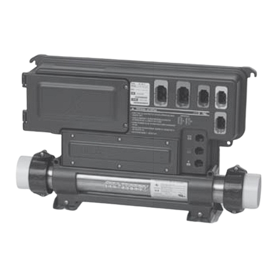
Page 8: In.xe Overview
Accessory fuse Pump 2 fuse Pump 1 fuse Pump 1 Pump 2 connector connector 2 connectors for outputs controlled by independent Installation brackets relays (for oz, cp, light, Transformer fuse blower or any other ac- Main power... -
Page 9: Overview
Front view Side view 17 .38" (441.5 mm) 5.51" (140 mm) (140 mm) 2.75" 11.75" (298.5 mm) (69.9mm) 5.69" (144.5mm) 4.5" (114.3 mm) 19.32" Ø.25" 5.37" 5.37" (490.7 mm) (6 mm) (136.4 mm) 6" 3"... -
Page 10: In.k200 Dimensions
In.k200™ dimensions: Features: LED display 4 Keys 8 light indicators in.link™ connector 2" (51 mm) Mechanical Specs: Weight: 0.41 kg (0.9 lbs) Dimensions (W x H x D): Front Panel: 120 mm x 51 mm x 43 mm (4.75... -
Page 11: In.xe Installation
Floor installation procedure 4" The following material is Slide back side of the unit's feet Now fi rmly attach unit to Note: The spa pack must be recommended: into the guide plate. It should wooden base by using the installed at least 4 inches above easily slide into place. -
Page 12: Wall Installation
Wall installation procedure The following material is In the case of a flat wooden Firmly attach lower mounting Note: Make sure these (2) recommended: surface: select the most holes on each side of the pack screws and (2) washers are... -
Page 13: Installing The In.k200
& connections in.xe Installing the in.k200™ " 67 mm The keypad should be installed directly onto the spa (or very close to it) so that it is easily accessible to the user. • To install the in.k200™, drill two 25 mm (1”) diameter holes at 67 mm (2 5/8”) from center to center as illustrated. -
Page 14: Connecting Main Keypad To In.xe
& connections Connecting main keypad to in.xe in.k200 The in.k200 comes with a 10 ft cable and an in.link connector. To connect the in.k200, simply insert its in.link connector into the appropriate keypad connector (as illustrated) Connect the main keypad... -
Page 15: Electrical Wiring North American Model In.xe
GFCI panel This product must always be connected to a circuit protected by a ground fault interrupter. Proper wiring of the electrical service box, GFCI and in.xe terminal block is essential! Check your electrical code for local regulations. Only copper wire should be used, never aluminum. - Page 16 To install the wiring for the Strip away 1" of each wire Push the color-coded wires Connect the bonding conduc- in.xe spa control, you'll need a insulation. into the terminals as indicated tor to the bonding lug on the Phillips screwdriver and a fl at on the sticker and use the fl...
-
Page 17: Electrical Wiring European Model In.xe.ce
Electrical wiring North American model in.xe Electrical wiring European model in.xe.ce Single-phase Dual-phase For 240 VAC (4 wires) For 120 VAC (*3 wires) In.xe.ce 230 VAC or Warning! 230/400 VAC In.xe.ce models must always Correct wiring of the electrical... -
Page 18: Heater Connections
Connections for 120v VAC heater (4KW or 2 KW) heater (1KW) Heat.wav heater In.xe comes with a high A watertight panel protects the The heat.wav heater is factory confi gured 240v /4 kW (or performance heat.wav heater. 2KW), but it can be converted to a dedicated 120v / 1kW by a heater and probe connectors. -
Page 19: In.link Connectors
Low voltage In.link connectors Latch snap & strain relief Watertight design UL & CE In.xe features in.links connectors with colored and tagged A latch mechanism is provided The female connector comes polarizers. This new plug and connector technology has been... - Page 20 Connector Map Female connector on Spa Pack Pump 1 Pump 2 Blower Ozonator connector connector connector connector Direct connector In.link output connectors: High-Current - HC connectors: Keypad connector Output Typical Device Out 1 Pump 1 Comm Out 2...
- Page 21 Assembly 240v cable kit in.link for in.xe High Current High Current Low Current Low Current Gecko P/N Description Typical use Cable Length Cable in.link HC 2S 600DB0821 dual-output loads up to 15 FLA (pump dual speed) 14/4 96"...
- Page 22 Assembly 120 v cable kit in.link for in.xe Assembly 240v cable kit in.link for in.xe (continuation) Gecko P/N Description Typical use Gecko P/N Description Typical use LC Keying LC Keying 9917-100894 Keying cable LC - BL - blue...
- Page 23 Assembly 120 v cable kit in.link for in.xe (continuation) High Current Low Current Gecko P/N Description Typical use Cable Length Cable in.link HC 2S 9920-401239 dual-output loads up to 15 FLA (pump dual speed) 14/4 96" 15A 120V 8FT Cable in.link HC 1S...
-
Page 24: Power-Up & Breaker Setting
Valuable Tips Make sure that all valves are open in the spa plumbing and that you There is no mechanical switch in the in.xe heater. Instead in.xe systems have integrated in.flo technology. The in.flo is an all have a good water flow circulating from the primary pump electronic dry-fire protection device built-in in.xe's heater. - Page 25 & breaker setting �� Make sure all accessories It is important to specify the The values displayed by the Use Up or Down button to are linked to the bonding current rating of the GFCI used system correspond to 0.8 of select the desired value.
-
Page 26: Programming The In Xe
The keypad display will show Use the Up/Down key to If at power-up of the system Although every in.xe spa pack L xx where "xx" represents the choose the new desired low your keypad display shows is factory set, in certain cases previous confi... - Page 27 Low Level Configuration Selection Chart Heater Config. # CP configuration Ozone configuration Filter Type Pump Always on Clean, P1L Always on Purge On during Filter cycle, with P1 Clean, P1L Duration filtration On during Filter cycle, with CP...
- Page 28 In the event where none of the pre-determined low level program To access this menu, press and hold Prog. (or Light key) configurations built in the in.xe system suit your spa equipment for 30 seconds. Use Up or Down key to choose setting.
- Page 29 Parameter Display Options Description Purge only = 0 Filter Config With Circ. Pump = 1 Filter cycle configuration With Pump #1, Low speed = 2 °F = 0 Temp. Units Temperature units used on display °C = 1...
-
Page 30: In.k200
Easy to install, in.k200 comes with an in.link connector. Note: The in.xe spa control is also compatible with the following keypads: in.k200, in.k400, in.k450 in.k600 (static). K-19, k-35 and k-8 (with in.link connector). -
Page 31: Function Description
Pump 1 Pump 2 Blower Light Filter Heater Set Point Smart Winter Mode indicator indicator indicator indicator indicator indicator indicator indicator �� Key 2 Light key Key 1 Up/Down key... -
Page 32: Instructions
�� �� �� �� �� �� �� Key 1 Key 2 Key 2 Light key 2 Pump (or single (2 Pump/Blower) pump/blower) Press key to turn Pump 1 Press key to turn Pump 2 Press to turn Pump 2 on at Press key to turn light on. - Page 33 �� Off Mode Up/Down key Programming the system Setting fi lter cycle duration This mode allows you to Use Up or Down key to set Depending on system confi gu- Press and hold key until Light stop all outputs for 30 min- desired water temperature.
- Page 34 ���� ���� Filter cycle frequency Programming purge cycles Purge cycle frequency Setting the temperature display units Press key again. The dis- To program the purge cycles, Press and hold key until Quick press key again. Light Light Light play will show , with "...
- Page 35 Water temperature regulation Smart Winter Mode Cooldown After heating the spa water to In a regulation cycle, the system If the readings received from Our Smart Winter Mode the desired Set Point, the heater fi rst generates water fl ow...
-
Page 36: Typical Settings
In.xe typical settings: Ajustable Regulating Set Point: 59°F (15°C) to 104°F (40°C) Factory Default Set Point: Typical 95°F (35°C) / Max 100°F (38°C) Filter Cycle Duration: 0 to 24 hrs / Factory set at 2hrs Filter Cycle Frequency:... -
Page 37: Spa Pack Error Codes Summary
In.xe error codes An internal hardware error has been detected in in.xe. Error codes indicate a failure condition or a problem which needs to be corrected to ensure proper functioning of the system. Both the error code and the water temperature are alternatively displayed. - Page 38 No low level confi guration software has been downloaded into the system. Temperature inside the spa skirt is too high, causing the internal temperature in the in.xe to increase above normal limits. Water temperature in the spa has reached 108°F. Do not enter spa water!
-
Page 39: Hr Error Condition
Flow chart Step-by-Step Restart the Replace Spa Pack Spa Pack, and start if problem & stop all persist. outputs. • Restart the Spa Pack and start & stop all pumps and blower. • If error reappears, replace in.xe Spa Pack. -
Page 40: Prr Error Condition
Prr error condition / fl ow chart & step by step Regulation probe issue Flow chart Step-by-Step Verify if Replace Replace regulation heater if Spa Pack, probe is problem if problem properly persist. persist. connected. • Verify if regulation probe (located above the heater) is properly connected. -
Page 41: Hl Error Condition
HL error condition fl ow chart The system has shut down because the temperature at the heater has reached 119°F (48°C). Remove spa cover Wait until spa cools (even during the night) down (add cold water if needed). Start blower, if spa is Reset system.*... - Page 42 HL error condition step-by-step HL Probe & Temp Probe Water temperature at the heater has reached 119°F 1• Measure the temperature 2• If reading is below 119°F: 3• If reading is 119°F or higher: with a DIGITAL thermo- meter and compare its a- Check if heater barrel •...
- Page 43 HL error condition step-by-step Ground If weather is very hot: If hot weather is not a factor: To shorten filter cycle duration: 1• Remove spa cover (even 2•Lower Set Point below 6• Press and hold Light key for 3• With a voltmeter, read during the night).
-
Page 44: Flo Error Condition
FLO error condition flow chart The system did not detect any water flow while the primary pump was running. Follow Troubleshooting Flow Chart below to identify the problem: Make sure that the low-level programming has been properly set, with or without circulation pump (depending on your system configuration). -
Page 45: Upl Error Condition
• New low level confi guration high enough. software needs to be • Make sure that the pump downloaded into the in.xe associated to the heater • Check and remove anything spa system, without it the (primary pump) is running. -
Page 46: Aoh Error Condition
AOH error condition chart & step-by-step Temperature inside the spa equipment compartment is too high Flow chart Step-by-Step Remove spa skirt Ensure and let Replace adequate system Spa Pack, water cool if problem level in down, persist. spa for... -
Page 47: Oh Error Condition
OH error condition chart & step-by-step Water temp. in the spa has reached 108°F Flow chart Step-by-Step Remove spa cover Replace Add cold and let water and Spa Pack, system cool lower fi lter if problem down, until cycles. -
Page 48: Pump 1 Doesn't Work
"Pump 1 doesn't work" fl ow chart If Pump 1 is not working, follow this troubleshooting fl ow chart: Refer to specifi c section indicated Measure Replace by error message. voltage on Pump 1. the board for both speeds. - Page 49 "Pump 1 doesn't work" step-by-step �� �� Pump 1 does not work! • Verify if “Pump 1” indicator • Check for an error condition • If “Pump 1” indicator does not appear, use a spare keypad appears on keypad display to verify if keypad is defective.
- Page 50 "Pump 1 doesn't work" step-by-step Pump 1 fuse Pin 3 Pin 6 Pin 1 Pin 1 240 VAC at P1 connector: 240 VAC at P1 connector: 240 VAC at P1 connector: 240 VAC 240 VAC at P1 connector: 240 VAC at P1 connector: Pin 3 &...
-
Page 51: Pump 2 Or Blower Doesn't Work
"Pump 2 or blower doesn't work" flow chart If Pump 2 or blower is not working, follow this troubleshooting flow chart: Refer to specific section indicated Replace by error message. Pump 2 Measure or blower. voltage on the board. - Page 52 "Pump 2 or blower doesn't work" steb-by-step �� �� Pump 2 or blower is not working! • Verify if “Pump 2” or "Blower" • Check for an error condition • If “Pump 2” or "Blower" indicator does not appear, use a spare indicator appears on keypad on keypad display.
- Page 53 "Pump 2 or blower doesn't work" steb-by-step Pump 2 fuse Pin 6 Pin 2 Pin 1 Pin 1 240 VAC at P2 connector: 240 VAC at P2 connector: 240 VAC at P2 connector: 240 VAC 240 VAC at P2 connector: Pin 2 &...
-
Page 54: Circulation Pump Doesn't Work
"Circulation pump doesn't work" flow chart If Circulation pump is not working, follow this troubleshooting flow chart: Replace Cir. Pump. Do you read 120 VAC for a Verify if low level 120 VAC Cir. programming has Pump (or 240 VAC been configured... - Page 55 "Circulation pump doesn't work" step-by-step Pin 2 �� Pin 1 240 VAC at CP connector: Pin 2 & Pin 1 Accessory fuse If Circulation pump is not working: Pin 2 Pin 5 • Verify low level program- • If you don't get a voltage 120 VAC at CP connector: ming confi...
-
Page 56: Ozonator Doesn't Work
"Ozonator doesn't work" flow chart If Ozonator is not working, follow this troubleshooting flow chart: Ozonator output will be shut down when Pump 1, Pump 2 or blower have been turned on manually. Replace ozonator. Do you read 120 VAC for a Replace Spa Pack Has “Filter Cycle”... - Page 57 "Ozonator doesn't work" step-by-step Pin 2 �� Pin 1 240 VAC at O3 connector: 240 VAC at O3 connector: 240 VAC at O3 connector: 240 VAC Pin 2 & Pin 1 Accessory fuse Pin 2 If Ozonator is not working: Pin 5 •...
-
Page 58: Nothing Seems To Work
"Nothing seems to work" flow chart If nothing seems to work, turn off the main breaker off and visually inspect power input cable, gently pull on it to make sure is properly tighten. Then, follow this troubleshooting flow chart:... - Page 59 "Nothing seems to work" step-by-step Nothing seems to work! For 120 VAC Systems • Measure voltage between • Measure voltage between • Measure voltage between • Verify that all screws are line 1 and neutral. line 2 and neutral.
- Page 60 "Nothing seems to work" step-by-step Transformer fuse • Verify if keypad is correctly connected to the Spa Pack. • Replace transformer fuse. • If problem persists, replace Spa Pack.
-
Page 61: Spa Not Heating
"Spa not heating" fl ow chart If spa is not heating, follow this troubleshooting fl ow chart: Refer to specifi c Replace section referred heater. to error message. Any error messages Are heater Replace (FLO, HL, screws properly heater. - Page 62 • In the case of the European try to raise water temperature started yet. 240 VAC: Line 1 & Line 2 model in.xe.ce only, replace by increasing the Set Point 120 VAC: Line 1 & Neutral accessory fuse. 2°F higher than actual water temperature.
-
Page 63: Keypad Doesn't Seem To Work
"Keypad doesn't seem to work" step-by-step Keypad doesn’t seem to work! Keypad connector If a keypad doesn’t seem to work: • Verify keypad connections and try spare keypad. • Replace keypad if problem is corrected. • Replace in.xe if problem is not corrected. -
Page 64: Gfci Trips
Verify if GFCI is properly connected. shock hazard. All electrical installations should be done by qualified personnel only. If it's not, verify GFCI diagram and reconnect it. Verify in.xe pack wiring (make sure that the neutral and the ground have not been inverted). -
Page 65: In.xe Step By Step Fi Eld Replacement Procedure
™ Step by Step Field Replacement Procedure As part of our technical support services, this section provides step by step proper methods to facilitate the replacement of in.xe spa packs systems in the field. Tools needed: • Phillips & flat screwdrivers •... - Page 66 Pumps, Blower or on the terminals of the terminal identify the spa Flow Shut Off any other accessories. When replacing an in.xe spa block. Valves. Make sure that both pack, its very important to make Flow Shut Off Valves which...
- Page 67 Disconnect the grounding Using an Open-Ended outputs. e.g.: main keypad, light cable from the Bonding Lug of Adjustable Wrench loosen or any other accessory. the in.xe Spa Pack. both 2" plastic nuts at each end of the in.xe heater, as illustrated.
- Page 68 Note: the procedure on keypad options etc. Ideally, the new Note: the in.xe can be also wall- the guide plate that holds the replacement shown here is for replacement keypad should be mounted.
- Page 69 Orient the cable's connector Make sure that the keypad is unwanted residue left over towards the in.xe pack to well aligned and rests perfectly from the old keypad. facilitate its connection later. in the recess of the spa.
- Page 70 Secure the keypad in place. Place a rubber 2" O'ring gasket When installing the new in.xe Install the new in.xe spa pack in Insure that its adhesive strip at the end of each heater nut, to spa pack, slide back side of the the spa plumbing.
- Page 71 fi eld replacement procedure Screw fi ttings to joint to the spa Finally, follow same procedure pipe system. Making sure that in reverse order to connect the piping and nut threads are replacement in.xe spa pack. not over tighten.
- Page 72 Warning! Before starting removal procedure be sure to: • Turn off electric power to the the unit. • Ensure spa water valves are closed (or that the spa is drained). Using a Phillips screwdriver, loosen the six (6) screws that hold the heater connections door in place.
-
Page 73: How To Replace The Heater
Ground HL Probe & in.fl o Ground HL Probe & in.fl o Temp Probe Temp Probe 120 VAC Heater (1 KW) 240 VAC Heater (4KW or 2 KW) Use a Phillips screwdriver to loosen the terminals and remove all electrical heater connections: Neutral Line (N), Line 1 (L1), Line 2 (L2) and Ground Line (Ground). - Page 74 After disconnecting all electrical heater connections, loosen and remove the two (2) heater nuts retaining the heater. Disengage heater from in.xe pack by slightly twisting in such way that the bottom of the heater comes out first and pull the heater away from the pack.
-
Page 75: Specifications
UL/CSA electrical specifications in.xe.ce TUV electrical specifications Input rating : 120/240 VAC nominal (+ 5/- 10 %) Input rating : 230/400 VAC nominal (+ 5/- 10 %) (2 lines required with neutral) 48 A Max, (2-phase system) 20 A Max per phase... - Page 76 EN61000-3-3 • Both front covers (heater and input wiring) are closed and screwed shut. The in.xe.ce is lab tested to IPx5 enclosure protection levels. • A suitable waterproof strain-relief/bushing is used for the cable entry into the pack. • Any unused in.link connection (HC, LC, or low voltage) is plugged...
- Page 77 100%...
- Page 78 Advanced electronics! Water resistance! Gecko Alliance 9919-100784 450 des Canetons, Quebec City (QC) G2E 5W6 Canada, 1.800.78.GECKO Rev. 12/10 9225 Stellar Court, Corona, CA 92883 USA , 951.667 .2000 © 2010 Groupe Gecko Alliance Inc. www.geckoalliance.com TM trade-marks of/marques de commerce de Groupe Gecko Alliance Inc.
Need help?
Do you have a question about the in.xe and is the answer not in the manual?
Questions and answers