Table of Contents
Advertisement
Quick Links
SW1001
SW1002
SWITCH MAINFRAME
Be sure to read this manual
before using the device
When using the device for the
first time
Part Names and Functions
Measurement Flowchart
Preparation for Measurements p. 13
June 2018 Edition 1
SW1001A961-00 18-06H
Safety Information
Troubleshooting
Troubleshooting
p. 8
Error display and troubleshooting p. 126
p. 12
Instruction Manual
p. 4
p. 125
EN
Advertisement
Table of Contents
Troubleshooting

Subscribe to Our Youtube Channel
Related Manuals for Hioki SW1001

Summary of Contents for Hioki SW1001
- Page 1 SW1001 SW1002 Instruction Manual SWITCH MAINFRAME Be sure to read this manual Safety Information p. 4 before using the device When using the device for the Troubleshooting first time Part Names and Functions Troubleshooting p. 8 p. 125 Measurement Flowchart Error display and troubleshooting ...
-
Page 3: Table Of Contents
Contents Introduction ............1 Scan Function Confirming Package Contents ......2 Safety Information ..........4 Overview of the Scan Function ..39 Usage Notes ............4 Setting the Scan Channel ....40 Setting the Trigger Source for Overview Scan Operation ........40 Scan Operation ........41 Overview of Product .......7 Resetting Scan Operation ....42 Features... - Page 4 11.3 Accuracy Calculation Example ..141 ® ......111 Using Visual Basic 2013 Appendix Specifications 12.1 Measurement cable ......143 SW1001, SW1002 General 12.2 Measuring Object Short Circuit Specifications ........119 due to Relay Contact Welding ..145 SW1001, SW1002 Input 12.3 Rack Mount .........147 Specifications/Output ........148...
-
Page 5: Introduction
(hereafter referred to as simply “instrument”). Modules can be installed in 3 slots for the SW1001 and 12 slots for the SW1002. Other functions are common for all the models. -
Page 6: Confirming Package Contents
CD (USB driver)* * The latest version can be downloaded from our web site. Options The following options are available for the device. Contact your authorized Hioki distributor or reseller when ordering. Module Model SW9001 Multiplexer Module Model SW9002 Multiplexer Module... - Page 7 Confirming Package Contents Connection cable See: “Before measurement” (p. 5 ) Model L2004 Connection Cable Model L2108 Connection Cable Length: Approx. 910 mm Length: Approx. 840 mm Maximum rated voltage: 30 V peak Maximum rated voltage: 60 V DC, 30 V AC rms, 42.4 V peak Maximum rated voltage 30 V DC or less, no...
-
Page 8: Safety Information
• Before using the device the first time, verify that it operates normally to ensure that no damage occurred during storage or shipping. If you find any damage, contact your authorized Hioki distributor or reseller. This device is designed to measure voltages of 60 V or lower. Do not input voltages over 60 V or measure locations exceeding 60 V from the ground potential. - Page 9 Usage Notes Handling the device This device may cause interference if used in residential areas. Such use must be avoided unless the user takes special measures to reduce electromagnetic emissions to prevent interference to the reception of radio and television broadcasts. Before installing the module WARNING •...
- Page 10 • Keep discs inside a protective case and do not expose to direct sunlight, high temperature, or high humidity. • Hioki is not liable for any issues your computer system experiences in the course of using this disc.
-
Page 11: Overview
Overview 1.1 Overview of Product This device is a module type switching system that is ideal for multi-channel measurement of batteries. You can choose a main frame from two choices according to the required number of channels. You can also choose a module from two module types according to the instrument to be used with the device (2-wire/4-wire module and 4-terminal pair module). -
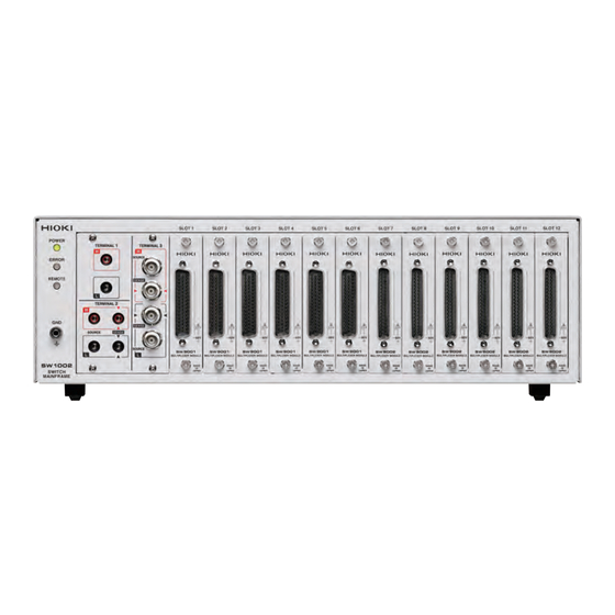
Page 12: Parts Names And Functions
Parts Names and Functions 1.3 Parts Names and Functions Front The illustration shown here is for the SW1001. Name Description Reference POWER lamp Lights up when the main frame power is on. p. 2 3 Lights up for self-test at the time of startup and p. ... -
Page 13: Communication 9
Parts Names and Functions Rear The illustration shown here is for the SW1001. Name Description Reference Power switch Turns on/off the power. p. 2 3 Power inlet Used to connect the provided power cord. p. 2 3 EXT. I/O terminal Used to connect the device to be externally controlled. -
Page 14: Block Diagram
Block Diagram 1.4 Block Diagram The configuration of this device is shown in the following block diagram. Switch Mainframe Internal analog bus Terminal Module Module EXT. I/O Connection cable Measurement cable PC/PLC Instrument Measuring object... -
Page 15: Glossary
Glossary 1.5 Glossary Terms Description Reference Measurement cable Connects the measuring object and the module. p. 1 43 It is prepared by the customer. Connection cable Connects the switch mainframe and instrument. p. 1 9 Prepare the optional cable. Terminal Connects the instrument. -
Page 16: Measurement Flowchart
Measurement Flowchart 1.6 Measurement Flowchart Thoroughly read “Usage Notes” (p. 4 ) beforehand. Installation, connection, and turning on of power Installing the device. (p. 4 ) Attaching the module to the device. (p. 1 5) Connecting the measurement cable to the module. (p. 1 8) Connecting the device and the instrument using the connection cable. -
Page 17: Preparation For Measurements
Connect the PC to the device and instrument via separate communications interfaces. Control the device to switch channels and control the instrument to configure settings, perform measurement, and acquire measured values. See: “3.2 Overview of Channel Switching” (p. 2 7) SW1001 LAN/USB/RS-232C Instrument LAN/USB/RS-232C Controlling an instrument via the device You can also use the device’s functionality for forwarding communication commands to control... - Page 18 Performing automatic scan measurement using EXT. I/O (using the communication command forwarding function) Furthermore, you can perform automatic scan measurement over a single communications interface by using the device’s communication command forwarding function. INSTRUMENT connector SW1001 Instrument LAN/USB/RS-232C RS-232C only EXT. I/O Connecting two instruments You can perform measurement by connecting two instruments to the device.
-
Page 19: Installing The Module
Installing the Module 2.2 Installing the Module Thoroughly read “Before installing the module” (p. 5 ) beforehand. The following settings are initialized when you install a new module into a slot or change the type of module installed in a given slot. •... -
Page 20: Removing The Module
Removing the Module Insert the module to the back. Align with the guide rail Tighten the two screws to secure the module in place. Screw 2.3 Removing the Module Required items: Phillips screwdriver (No. 2), antistatic gloves Front Touch the terminal with bare hands. - Page 21 Removing the Module Front Remove all the measurement cables connected to the device and module. (To prevent electric shock and short circuit of the measuring object.) Loosen the two screws. Screw Pull out the module. Attach the blank panel and tighten the two screws (M3 ×...
-
Page 22: Connecting The Measurement Cable
Connecting the Measurement Cable 2.4 Connecting the Measurement Cable WARNING Connect the measurement cable with the measuring object disconnected from the measurement cable. The measuring object may be shorted depending on the condition of the module switching circuit. Please provide a suitable measurement cable. See: “12.1 Measurement cable”... -
Page 23: Connecting The Connection Cable
Connecting the Connection Cable 2.5 Connecting the Connection Cable The connection cable is optional (p. 2 ). Connect the device to the instrument. For information on connecting the instrument, see the instruction manual of each instrument. Front Select the terminal and connection cable to be connected based on the instrument to be connected. Instrument Connection Connection... -
Page 24: Terminal 1
Connecting the Connection Cable CAUTION TERMINAL 2 TERMINAL 3 are internally conducted. Do not connect the instrument TERMINAL 2 TERMINAL 3 at the same time. Doing so may damage the instrument. TERMINAL 1 Turn off the device. Connect the connection cable to TERMINAL Front Black... -
Page 25: Terminal 3
Connecting the Connection Cable TERMINAL 3 Turn off the device. Connect the connection cable to TERMINAL Front Match the cable and the connection terminal signal. SOURCE-H (red) SENSE-H (red) SENSE-L (black) SOURCE-L (black) Turn the BNC connector to Check the direction of Align the grooves of the the grooves of the BNC BNC connector with the... -
Page 26: Setting The Communication Setting Mode
Setting the Communication Setting Mode 2.6 Setting the Communication Setting Mode The device uses the communications interface for control. You can select the fixed setting mode for initial communication settings or the user setting mode for user settings using the switch on the rear of the device. Specify the communication settings according to the interface to be used in the user setting mode. -
Page 27: Connecting The Power Cord
Connecting the Power Cord 2.7 Connecting the Power Cord Be sure to thoroughly read the separate document “Operating Precautions” before use. Rear Check that the power switch is off ( ). Check that the power voltage is within the range indicated on the rear of the device and connect the power cord to the power inlet. -
Page 28: When The Power Is Turned On
When the Power is Turned on 2.9 When the Power is Turned on Item Initialization description Channel relay All relays open Bus relay All relays open EXT. I/O CLOSE output signal Connection method Settings (for each slot) are saved with the settings backup command. Shield switching Settings (for each slot) are saved with the settings backup command. -
Page 29: Channel Switching
Thoroughly read "Usage Notes" (p. 4) beforehand. 3.1 Inspection before Measurement Verify that it operates normally to ensure that no damage occurred during storage or shipping. If you find any damage, contact your authorized Hioki distributor or reseller. Inspecting the device and peripheral devices Check item... -
Page 30: Checking For Relay Contact Welding
Send inspection No. of slot to be inspected inspection for this slot. Perform steps for all the slots. Module relay contact may be weld if it was conducted during inspection. Stop the use and contact your authorized Hioki distributor or reseller. -
Page 31: Overview Of Channel Switching
Overview of Channel Switching 3.2 Overview of Channel Switching This device connects to the internal analog bus by switching the relay of each module channel. The internal analog bus is connected to the terminal for connecting the instrument. The device is all controlled by communication commands. For details about the command, refer to the description of each item. -
Page 32: Procedure For Switching The Channel
Procedure for Switching the Channel 3.3 Procedure for Switching the Channel Switch the channel according to the following setting and procedure. • Selecting the connection method • Switching the shield • Selecting the channel Selecting the connection method The connection method can be selected for each slot. Selecting the connection method determines the terminal of the connection destination (instrument). -
Page 33: Switching The Shield
Procedure for Switching the Channel Switching the shield When the connection method is selected, the shield wire is connected to the specified connection destination. Specified shield switching setting (shielding connection destination) Module Connection method Shield connection destination 2-wire TERMINAL 1, LOW terminal SW9001 4-wire TERMINAL... -
Page 34: Selecting The Channel
Procedure for Switching the Channel Selecting the channel Select the slot and channel No. When the channel is selected, the specified slot of channel relay is closed, as well as the bus relay is also closed due to the connection method. Item Communication command [ROUTe]: CLOSe <... -
Page 35: Channel Switching Operation
Channel Switching Operation 3.4 Channel Switching Operation When the channel is selected (closed), channel switching is performed according to the following flow. Channel switching Enabled channel Previous channel Selected channel Relay operation Close Open Close Operation Channel Settling time standby time delay EXT. -
Page 36: Measurement Between Two Instruments
Measurement between Two Instruments 3.5 Measurement between Two Instruments Changing the connection method enables measurement to be performed by switching between two instruments according to the application. Example: Measure the internal resistance of 8 batteries using BT3562 and measure the OCV using DM7276. - Page 37 Measurement between Two Instruments Control example using communication command Set the SLOT 1 connection method to 4-wire (connect to [SW1001] :SYST:MOD:WIRE:MODE 1,WIRE4 TERMINAL [SW1001] :CLOSE 101 Select SLOT 1, CH1. [SW1001] ∗ OPC? Check that the channel relay has been closed.
- Page 38 The signal is connected to TERMINAL Repeat channel selection and measurement using DM7276 (external potential measurement for batteries). Control example using communication command [SW1001] :SYST:MOD:WIRE:MODE 1,WIRE4 SLOT 1 to 4-wire (connect to TERMINAL [SW1001]...
-
Page 39: Precautions For Measurement
Precautions for Measurement 3.6 Precautions for Measurement Use in combination with BT3562 or BT3563 Ω Contact check does not operate properly at 3000 range. Also be aware that contact check cannot be performed properly in the voltage function, either. Use in combination with BT4560 Use the device with BT4560 for external trigger measurement or single measurement using the :READ? command. - Page 40 Precautions for Measurement Influence of thermoelectric power Be aware of the thermoelectric power when a voltage accuracy of a few µV is required. Install the device and instrument in a constant temperature environment and fully adjust them to the ambient temperature before use. Especially prevent uneven temperatures at the terminal.
-
Page 41: Channel Delay Function
Channel Delay Function 3.7 Channel Delay Function The delay time after channel switching can be specified. When the specified delay time elapses after the channel relay is closed, a CLOSE signal of EXT. I/O is output. If the measurement response time for the instrument needs to be ensured, set the delay time. The required delay time depends on the instrument to be used and the measuring object. - Page 42 Precautions for Measurement...
-
Page 43: Scan Function
Scan Function Thoroughly read "Usage Notes" (p. 4 ) beforehand. 4.1 Overview of the Scan Function For scanning, specify the channel range (scan list) in advance and switch the channel in order. Channel switching (scan channel moving forward) can be performed using EXT. I/O or communications. -
Page 44: Setting The Scan Channel
Setting the Scan Channel 4.2 Setting the Scan Channel The channels to be scanned need to be registered as a scan list. Specify the start and end channels. An individual channel list can also be specified. Item Communication command [:ROUTe]:SCAN<(@ Channel list )> Setting <(@ Channel list )>... -
Page 45: Scan Operation
Scan Operation 4.4 Scan Operation * TRG Scanning is started by the SCAN signal of EXT. I/O or the communication command. The scan * TRG channel is moved forward by the SCAN signal or the command. * TRG When the channel is the final channel, scanning is completed by the SCAN signal or the command, and all relay is opened and goes back to the beginning of the scan list. -
Page 46: Resetting Scan Operation
Resetting Scan Operation 4.5 Resetting Scan Operation Scanning is reset and stopped by the SCAN_RESET signal of EXT. I/O or the communication :ABORt command. All channel relays are opened and goes back to the beginning of the scan list. -
Page 47: Scan Measurement Example
Scan Measurement Example 4.6 Scan Measurement Example The following example shows scan measurement with the SW1001 and BT3562 connected using EXT. I/O. For acquiring measured values, the BT3562 data output function is used. Scan measurement start RS-232C BT3562 setting External trigger... - Page 48 Resetting Scan Operation...
-
Page 49: Other Functions
Other Functions 5.1 Checking the Device Status The following items can be checked using the free software for the SW1001 series (downloaded from our website). • Module information of each slot Slot position, model, serial number, and opening/closing frequency of each relay... - Page 50 Checking the Device Status...
-
Page 51: Initialization
Initialization 6.1 Initialization Settings The device is in the initial state at the time of shipment and at the time of initialization using commands. However, communications settings will not be initialized if the initialization is triggered by command. Settings that are backed up can be stored so that they persist even when the power is turned off by :SYSTem:BACKup executing the command. - Page 52 Initialization Settings...
-
Page 53: External Control (Ext. I/O)
External Control (EXT. I/O) Thoroughly read “Before starting the external control” (p. 6 ) beforehand. Connecting the instrument and the EXT. I/O terminal allows you to perform measurement in synchronization with channel switching when using the scan function. Also scan control can be performed from the PLC and other devices. -
Page 54: Switching Between Sinking Current (Npn) And Sourcing Current (Pnp)
Switching between Sinking Current (NPN) and Sourcing Current (PNP) 7.2 Switching between Sinking Current (NPN) and Sourcing Current (PNP) Thoroughly read “Before starting the external control” (p. 6 ) beforehand. The applicable PLC type can be changed using the EXT. I/O MODE change-over switch. -
Page 55: Connection
Connection 7.3 Connection Device connector and compatible connectors Thoroughly read “Before starting the external control” (p. 6 ) beforehand. Rear 5 4 3 2 1 9 8 7 6 Connectors used (device unit side) • D-SUB 9-pin Female #4-40 inch screw Compatible connectors •... -
Page 56: Signal Functions
Connection to the instrument An example of connecting the device and instrument for scan measurement is shown below. Example: Connecting the BT3562 Battery HiTester Set the BT3562 to the external trigger mode. SW1001 (SW1002) BT3562 Rear Rear 5 4 3 2 1... -
Page 57: Timing Chart
Timing Chart 7.4 Timing Chart The level of each signal shows the contact on/off status. In the sourcing current (PNP) setting, HIGH and LOW in the timing chart are the same as the voltage level of the EXT. I/O terminal. HIGH and LOW are reversed for the voltage level in the sinking current (NPN) setting. - Page 58 Timing Chart (2) Scan operation reset When the SCAN_RESET signal is input during scan operation, the scan operation is stopped and the channel relay is opened. When the scan signal is input with the scan operation reset, the scan operation is restarted from the beginning. SCAN SCAN_RESET Open...
-
Page 59: Internal Circuit Configuration
Internal Circuit Configuration 7.5 Internal Circuit Configuration NPN setting Do not connect external power to one pin. This device PLC, etc. ISO_5 V Ω Ω Output SCAN SCAN_RESET Common EXT. I/O MODE Internal isolated selector power supply PLC, etc. Ω Input CLOSE Zener voltage 30 V... -
Page 60: Electrical Specifications
Internal Circuit Configuration PNP setting Use ISO_COM for the common terminal for both the input and output signals. Do not connect external power to one pin. PLC, etc. This device ISO_5 V Ω Ω Output SCAN SCAN_RESET Common EXT. I/O MODE Internal isolated selector power supply... -
Page 61: Connection Examples
Internal Circuit Configuration Connection examples Input circuit connection examples This device This device Input Input ISO_COM ISO_COM Connection to the switch Connection to the relay This device This device Input Output Input Output ISO_COM Common ISO_COM Common Connection to the PLC output (NPN output) Connection to the PLC output (PNP output) - Page 62 Internal Circuit Configuration Output circuit connection examples This device This device Output Output 50 mA max. 50 mA max. ISO_COM ISO_COM 30 V max. Connection to the relay Connection to the LED This device Output This device Output 50 mA max. Negative-true Output logic output...
-
Page 63: Communication Function
All of the interfaces can be used and do not need to be specified. To avoid malfunction, however, use only one interface for control. For the specifications, see "9.4 SW1001, SW1002 Interface Specifications" (p. 1 23). 8.2 Setting the Communication Setting Mode The communication setting mode needs to be specified before using the communication function. -
Page 64: Lan Interface
LAN Interface 8.3 LAN Interface This device is equipped with an Ethernet 100BASE-TX interface as standard. The device is connected to the network using a LAN cable (up to 100 m) compatible with 10BASE-T or 100BASE-TX, and then the device can be controlled using the PC. Networking the device and PC Perform one-to-one connection between the device and PC. -
Page 65: Communication Condition Settings
LAN Interface Communication condition settings To be checked before setting The settings are different when the device and external device are connected to the existing network and when the device and a PC are connected to a new network. Connecting the device to the existing network The network administrator (department) needs to assign the following items in advance. -
Page 66: Setting Lan Communications
LAN Interface Setting LAN communications Set the commands shown below for the LAN communications. :SYSTem:COMMunicate:LAN:IPADdress <Value 1>,<Value 2>,<Value 3>,<Value 4> Set the IP address for the device. :SYSTem:COMMunicate:LAN:SMASK <Value 1>,<Value 2>,<Value 3>,<Value 4> Set the LAN subnet mask. :SYSTem:COMMunicate:LAN:GATeway <Value 1>,<Value 2>,<Value 3>,<Value 4> Set the address for the default gateway. -
Page 67: Connecting The Lan Cable
LAN Interface Connecting the LAN cable Thoroughly read "Before connecting the communications cables" (p. 6 ) beforehand. Connect a LAN cable to the LAN connector of the device. Recommended cable: Model 9642 LAN cable (optional), 100BASE-TX or 10BASE-T compatible LAN cable (up to 100 m, straight cable and cross cable can be used) Rear LAN cable Device LAN connector... -
Page 68: Usb Interface
• A warning message is displayed since the Windows logo has not been acquired. Ignore the message and continue the installation procedure. Uninstallation procedure Uninstall the USB driver when it is no longer required. Click [Control Panel] [Uninstall a program], and then delete [HIOKI USB CDC Driver]. -
Page 69: Connecting The Usb Cable
USB Interface Connecting the USB cable Thoroughly read "Before connecting the communications cables" (p. 6 ) beforehand. Recommended cable: Hioki model L1002 USB Cable (A-B) Rear Type B USB interface of the PC... -
Page 70: Rs-232C Interface
RS-232C Interface 8.5 RS-232C Interface Connecting the RS-232C cable Thoroughly read "Before connecting the communications cables" (p. 6 ) beforehand. HOST RS-232C Connect the RS-232 cable to the connector. Be sure to tighten the screws when connecting the cable. Rear 1 2 3 4 5 6 7 8 9 Connectors used (device unit side) - Page 71 Use a D-sub 9-pin female/female crossover cable. Connect the HOST RS-232C connector of the device and the COM port of the PC. Recommended cable: Hioki modeI 9637 RS-232C cable (9pin-9pin/1.8 m) Cross connections D-sub 9-pin female D-sub 9-pin female Device side PC side Pin No.
-
Page 72: Setting Rs-232C Communications
RS-232C Interface Setting RS-232C communications Set the commands shown below for the transmission speed. :SYSTem:COMMunicate:RS232C:SPEED <9600/19200/38400> The speed can be selected from 9600 bps, 19200 bps, or 38400 bps. The speed setting is immediately changed. Other RS-232C communication parameters are fixed to 8 for data bit length, 1 for stop bit, none for parity check, and none for flow control. -
Page 73: Communication Command Forwarding Function
Communication Command Forwarding Function 8.6 Communication Command Forwarding Function The communication command forwarding function forwards commands sent from the host to the communication interface (RS-232C) of the instrument without making any change. • It is possible to control both the device and instrument using one communication port. •... - Page 74 Communication Command Forwarding Function Connection method INSTRUMENT When using the communication command forwarding function, connect the RS-232C connector of the device and the RS-232C connector of the instrument. SW1001 (SW1002) Instrument Rear Rear Use the RS-232C cross cable. INSTRUMENT RS-232C...
-
Page 75: Communication Method
Communication Method 8.7 Communication Method Various messages are supported for controlling the device through the interfaces. Messages can be either program messages, sent from the PC to the device, or response messages, sent from the device to the PC. Program messages This device Response message Message types are further categorized as follows. - Page 76 Communication Method Response messages When a query message is received, its syntax is checked and a response message is generated. If an error occurs when a query message is received, no response message is generated for that query. Command syntax Command names are chosen to mnemonically represent their function and can be abbreviated.
- Page 77 Communication Method Message terminators This device recognizes the following message terminators (delimiters). RS-232C CR, CR+LF CR, CR+LF Depending on the interface settings, the following can be selected as the terminator for response messages. RS-232C CR+LF CR+LF Reference: "Communication condition settings" (p. 6 1) Separators (1) Command program headers Multiple messages can be written in one line by separating them with semicolons (...
- Page 78 Communication Method Data formats The device uses character data and decimal numeric data depending on the command. (1) Character data Character data always begins with an alphabetic character, and subsequent characters may be either alphabetic or numeric. Character data is not case-sensitive, although response messages from the device are only upper case.
- Page 79 A colon ( ) is not required at the start of the header of a simple or compound command. However, to avoid confusion with abbreviated forms and operating mistakes, Hioki recommends to always place a colon ( ) at the start of a header.
-
Page 80: Output Queue And Input Buffer
Communication Method Output queue and input buffer Output queue Response messages are stored in the output queue until read by the controller. The output queue is also cleared in the following circumstances. • When the power is turned on • Query error At a minimum, the device’s output queue can buffer a 64-byte response message. -
Page 81: Status Byte Register
Communication Method Status Byte Register This device implements the status model defined by IEEE 488.2 with regard to the serial poll function using the service request line. The term “event” refers to any occurrence that generates a service request. Overview of service request occurrence Standard Event Register information Service Request (SRQ) - Page 82 Communication Method Status Byte Register (STB) During serial polling, the contents of the 8-bit Status Byte Register are sent from the instrument to the controller. When any Status Byte Register bit enabled by the Service Request Enable Register has switched from “0”...
-
Page 83: Event Registers
Communication Method Event Registers Status Query Register AND output of EV and EN COND <1> bit 0 bit 0 Status Byte Register <2> bit 1 bit 1 bit 2 bit 2 <4> AND output of EV and EN bit 3 <8>... - Page 84 Communication Method Standard Event Status Register (SESR) The Standard Event Status Register is an 8-bit register. If any bit in the Standard Event Status Register is set to “1” (within the enabled bits set by the Standard Event Status Enable Resister), bit 5 (ESB) of the Status Byte Register is set to “1”.
- Page 85 Communication Method Standard Event Status Enable Register (SESER) Setting any bit of the Standard Event Status Enable Register to “1” enables access to the corresponding bit of the Standard Event Status Register. Standard Event Status Register (SESR) and Standard Event Status Enable Register (SESER) bit 6 bit 5 bit 4...
- Page 86 Communication Method Device-specific Event Status Registers This device provides two Event Status Registers for controlling events. The Event Status Register is an 16-bit register. When any bit in one of these Event Status Registers enabled by its corresponding Enable Register is set to “1”, the following happens: •...
- Page 87 Communication Method Standard Operation Register Bit 15 – Unused Bit 14 – Unused Set to “1” when an error occurs (cleared when details are acquired from Bit 13 :SYSTem.ERRor? Bit 12 – Unused Bit 11 CLOSE Set to “1” when channel closing is completed. Bit 10 REMOTE Set to “1”...
- Page 88 Communication Method Status Query Register Bit 15 – Unused Bit 14 – Unused Bit 13 – Unused Bit 12 – Unused Bit 11 – Unused Bit 10 – Unused Bit 9 – Unused Bit 8 INFO_ERR Model information error Bit 7 BACKUP_ERR Setting backup error Bit 6...
- Page 89 Communication Method Register query and setting Register Query Setting * STB? Status Byte Register – * SRE? * SRE Service Request Enable Register * ESR? Standard Event Status Register – * ESE? * ESE Standard Event Status Enable Register :STATus:OPERation Condition Register of the Standard –...
-
Page 90: Initialization Items
Communication Method Initialization items : Yes, –: No * RST * CLS When the power Register is turned on Command Command Device-specific functions (range, etc.) – – Output queue – – Input buffer – – Status Byte Register –... -
Page 91: Message List
Message List 8.8 Message List Data Message Description Reference [ ]: Omissible, [ ]: Omissible ( ): Response data (<Manufacturer name>,<Model * IDN? p. 9 1 Queries the device ID (ID code). name>,<Serial No.>,<Software version>) * RST p. 9 1 Initializes the device. - Page 92 Message List Data Message Description Reference [ ]: Omissible, [ ]: Omissible ( ): Response data :ABORt p. 1 00 Reset of the scan operation. Initialize the device. :SYSTem:PRESet p. 1 06 * RST (Same setting as (<Error No.>,<Error Queries and clears the error :SYSTem:ERRor? p. ...
- Page 93 Message List Data Message Description Reference [ ]: Omissible, [ ]: Omissible ( ): Response data Sets the EXT. I/O input terminal filter :IO:FILTer:STATe <1/0/ON/OFF> function. p. 1 02 Queries the EXT. I/O input terminal :IO:FILTer:STATe? (<1/0>) filter function. <Filter time 0.05 to 0.50/ Sets the EXT.
-
Page 94: Message Reference
Message Reference 8.9 Message Reference Description < >: Indicates the contents (character or numeric parameters) of the data portion of a message. Character parameters are returned as all capital letters. Numeric Parameters: • NRf: Number format may be any of NR1, NR2 and NR3. •... -
Page 95: Standard Commands
Query device ID (ID code) * IDN? Syntax Query Response <Manufacturer name>,<Model name>,<Serial No.>,<Software version> * IDN? Example HIOKI,SW1001,123456789,V1.00 For the SW1002, the <Model name> is “SW1002”. (2) Internal operation commands Initializes the device. * RST Syntax Command Description Resets the device to its initial state. - Page 96 Message Reference (3) Synchronized commands Set the OPC of the SESR register when finished with all pending operations * OPC Syntax Command Description Sets “OPC bit 0” of the Standard Event Status Register (SESR) when the present operation is completed. The next command does not execute until the present operation is completed.
- Page 97 Message Reference Query Standard Event Status Register (SESR) * ESR? Syntax Query Response <0 to 255 (NR1)> Description Returns the SESR value. Unused bits (indicated in the following chart by “–”) return the value 0. bit 7 bit 6 bit 5 bit 4 bit 3 bit 2...
-
Page 98: Device-Specific Commands
Message Reference Device-specific commands (1) Event Status Register Query Condition Register of Standard Operation Register Group :STATus:OPERation:CONDition? Syntax Query Response <0 to 65535 (NR1)> Description Returns the present standard operation register value. Unused bits (indicated in the following chart by “–”) return the value 0. bit 15 bit 14 bit 13... - Page 99 Message Reference Query Condition Register of Status Query Register Group :STATus:QUEStionable:CONDition? Syntax Query Response <0 to 65535 (NR1)> Description Returns the present status query register value. Unused bits (indicated in the following chart by “–”) return the value 0. bit 15 bit 14 bit 13 bit 12...
- Page 100 :SYSTem:MODule:WIRE:MODE < Slot No.>,<Connection method> Syntax Command :SYSTem:MODule:WIRE:MODE? Slot No. > Query Response <Connection method> <Slot No.> = 1 - 3 (NR1) (SW1001) 1 - 12 (NR1) (SW1002) <Connection method> = WIRE2/WIRE4/TP4 WIRE2: 2-wire WIRE4: 4-wire TP4: 4-terminal Description Sets the connection method for each slot. Connection method selection determines the connection terminal for the instrument to which each channel is connected.
- Page 101 Command destination > :SYSTem:MODule:SHIeld? Slot No. > Query Response <Shield wire connection destination> <Slot No.> = 1 - 3 (NR1) (SW1001) 1 - 12 (NR1) (SW1002) <Shield wire connection destination> = OFF/GND/TERMinal1/ TERMinal2/TERMinal3/T1T3/SNS2L OFF: Not connected GND: Connected to ground...
- Page 102 :SYSTem:MODule:DELay? Slot No. > Query Response <Time> <Slot No.> = 1 to 3 (NR1) (SW1001) 1 to 12 (NR1) (SW1002) <Time> = 0 to 9.999 (NR2) [s] (MIN:0, MAX: 9.999, DEF: 0) Description Sets the additional delay time after relay operation (standby for the specified settling time occurs).
- Page 103 Message Reference (5) Scan Function Register and query scan list [:ROUTe]:SCAN<(@ Channel list )> Syntax Command [:ROUTe]:SCAN? Query Response <(@Channel list)> Specify the channel list in the following formats. <CH>,<CH>, ..., <CH> Specify the channels to be measured individually. <CHm>:<CHn> Specify from CHm to CHn consecutively.
- Page 104 Message Reference Query the number of scan lists that can be added. [:ROUTe]:SCAN:SIZE? Syntax Query Response 0 to 1000 (NR1) Description Checks the number of channels (remaining) that can be added to the scan list. Up to 1000 scan lists can be registered. :SCAN 101 Example :SCAN:SIZE?
- Page 105 Message Reference (6) Command forwarding function Set and query RS-232C communication speed of the communication command forwarding function :SYSTem:COMMunicate:FORWard:RS232C:SPEED Syntax Command <9600/19200/38400> :SYSTem:COMMunicate:FORWard:RS232C:SPEED? Query Response <9600/19200/38400> Description Set the communication speed of the RS-232C (communication command forwarding function). The speed setting is immediately changed. Other RS-232C communication parameters are fixed to 8 for data bit length, 1 for stop bit, None for parity check, and None for flow control.
- Page 106 Message Reference (7) EXT. I/O settings Set and query EXT. I/O input terminal filter function :IO:FILTer:STATe <1/0/ON/OFF> Syntax Command :IO:FILTer:STATe? Query Response <1/0> 1/ON The filter is activated. 0/OFF The filter is deactivated. Description Sets whether to activate or deactivate the filter function to prevent chattering for the SCAN of EXT.
- Page 107 Message Reference (8) RS-232C settings Set and query RS-232C communication speed :SYSTem:COMMunicate:RS232C:SPEED <9600/19200/38400> Syntax Command :SYSTem:COMMunicate:RS232C:SPEED? Query Response <9600/19200/38400> Description Sets the RS-232C communication speed. The speed setting is immediately changed. When the communication setting mode switch (DFLT/USER) is set to DFLT, the speed setting is fixed to 9600 bps regardless of the settings specified here.
- Page 108 Message Reference Set and query IP address :SYSTem:COMMunicate:LAN:IPADdress <Value 1>,<Value Syntax Command 2>,<Value 3>,<Value 4> :SYSTem:COMMunicate:LAN:IPADdress? Query Response <Value 1>,<Value 2>,<Value 3>,<Value 4> <Value 1> = 0 to 255 (NR1) <Value 2> = 0 to 255 (NR1) <Value 3> = 0 to 255 (NR1) <Value 4>...
- Page 109 Query slot module information :SYSTem:CTYPe? < Slot No. > Syntax Query Response <Manufacturer name>,<Model name>,<Serial No.> <Slot No.> = 1 to 3 (NR1) (SW1001) 1 to 12 (NR1) (SW1002) <Manufacturer name> = HIOKI 0 (Not attached) <Model name> = SW9001 (SW9001) SW9002 (SW9002) 0 (Not attached) <Serial No.>...
- Page 110 Query relay opening/closing frequency :SYSTem:MODule:COUNt? < Slot No. > [,<Relay No.>] Syntax Query Response <Slot No.> = 1 to 3 (NR1) (SW1001) 1 to 12 (NR1) (SW1002) <Opening/closing frequency> = 0 to 1000000000 (NR1) Description Returns to the specified relay opening/closing frequency.
-
Page 111: Sample Programs
Sample Programs 8.10 Sample Programs ® ® This section introduces how to create programs using Visual Basic 5.0, Visual Basic 6.0, or Visual ® Basic 2013. ® Using Visual Basic 5.0 or 6.0 ® These sample programs are created with Visual Basic 5.0 and 6.0. - Page 112 RS-232C/USB communications (Using Visual Basic Professional MS Comm) Using the DM7276 to perform scan measurement Connect the SW1001 and DM7276 to their respective COM ports and perform scan measurement from CH1 to CH22 for SLOT The USB interface can be used to communicate with the device in the same manner as the RS-232C interface.
- Page 113 Sample Programs Measure the internal resistance using the BT3562 and measure the OCV using the DM7276. Connect the SW1001 and BT3562, DM7276 to their respective COM ports and perform scan SLOT measurement of internal resistance and OCV from CH1 to CH11 for...
- Page 114 Sample Programs 'Write the CH1 to CH11 measurement data of SLOT 1 to a file. i = 0 For unit_no = 1 To 1 For ch_no = 1 To 11 ch_str = Format(unit_no, "00") & Format(ch_no, "00") Print #1, ch_str & "," & ir_str(i) & "," & ocv_str(i) 'Write measurement data to a file.
-
Page 115: Using Visual Basic ® 2013
Sample Programs ® Using Visual Basic 2013 ® This section describes how to use Visual Basic 2013 Express Edition to operate the unit from a PC via an RS-232C or USB interface, import measured values, and save measured values to a file. The procedure may differ slightly from the one described here depending on the environment of the ®... - Page 116 Sample Programs (2) Placing a button Click [Button] under [Common Controls] of [Toolbox]. Drag and drop the button onto the form layout screen. Change [Text] [Start Measurement] under [Properties]. [Start Measurement] button is placed on the form.
- Page 117 Sample Programs (3) Describing the code Double-click the placed button. The code editor appears. Enter the sample program into the code editor.
- Page 118 Sample Programs Select [File] – [Save All]. Check the save location and click [Save as].
- Page 119 Sample Programs Using the DM7276 to perform scan measurement Connect the SW1001 and DM7276 to their respective COM ports and perform scan measurement SLOT from CH1 to CH22 for The USB interface can be used to communicate with the device in the same manner as the RS- 232C interface.
- Page 120 Sample Programs 'Open all relays after the scan completes. sp1.WriteLine(":OPEN") writer1.Close() sp1.Close() sp2.Close() sp1.Dispose() sp2.Dispose() End Sub End Class...
- Page 121 Sample Programs Measure the internal resistance using the BT3562 and measure the OCV using the DM7276. Connect the SW1001 and BT3562, DM7276 to their respective COM ports and perform scan SLOT measurement of internal resistance and OCV from CH1 to CH11 for Imports System.IO.Ports...
- Page 122 Sample Programs 'Configure SLOT1 as a 2-wire connection. sp1.WriteLine(":SYST:MOD:WIRE:MODE 1,WIRE2") sp1.WriteLine("*OPC?") sp1.ReadLine() i = 0 For unit_no = 1 To 1 For ch_no = 12 To 22 'The 2-wire CH12 corresponds to the 4-wire CH1 sense. 'Create a string to specify the channel. ch_str = Format(unit_no, "00") + Format(ch_no, "00") 'Close the specified channel and wait for the operation to complete.
-
Page 123: Specifications
Power LED, error LED, and remote LED Interface USB, LAN, RS-232C (2 ports), EXT. I/O Dimensions SW1001: Approx. 215W × 132H × 420D mm (8.46"W × 5.20"H × 16.54"D) (excluding protrusion) SW1002: Approx. 430W × 132H × 420D mm (16.93"W × 5.20"H × 16.54"D) (excluding protrusion) Mass SW1001: Approx. -
Page 124: Sw1001, Sw1002 Input Specifications/Output Specifications/Measurement Specifications
SW1001, SW1002 Input Specifications/Output Specifications/Measurement Specifications 9.2 SW1001, SW1002 Input Specifications/Output Specifications/Measurement Specifications Basic specifications Number of slots 3 slots (SW1001), 12 slots (SW1002) Analog bus Number of systems 2-wire 4-system (automatic selection based on the module and connection method) Terminal BNC receptacle ×... -
Page 125: Sw1001, Sw1002 Functional Specifications
SW1001, SW1002 Functional Specifications 9.3 SW1001, SW1002 Functional Specifications Channel switching The specified slot and channel is connected to the analog bus based on the communication command. Connection method 2-wire Connect to TERMINAL 1 4-wire Connect to TERMINAL 2 TERMINAL 3... - Page 126 SW1001, SW1002 Functional Specifications Communication Changes to the “Fixed setting mode/User setting mode” in the communication settings setting change-over when the slide switch is toggled. function Fixed setting mode Communications can be performed via all LAN, USB, and RS-232C interfaces.
-
Page 127: Sw1001, Sw1002 Interface Specifications
SW1001, SW1002 Interface Specifications 9.4 SW1001, SW1002 Interface Specifications Applicable standard IEEE802.3 Transmission method 10BASE-T/100BASE-TX automatic recognition Full duplex Protocol TCP/IP Connector RJ-45 Communication Setting and measured value acquisition by using communications commands description Settings IP address, subnet mask, default gateway... -
Page 128: Ext. I/O
SW1001, SW1002 Interface Specifications Flow control None Protocol Non-procedure Communication Setting and measured value acquisition by using communications commands description Default setting Transmission speed: 9600 bps EXT. I/O Connector D-sub 9-pin, female, fixing stud screw #4-40 UNC Input Electrical Insulation... -
Page 129: Maintenance And Service
Maintenance and Service 10.1 Troubleshooting If damage is suspected, check “Before sending the device for repair” before contacting your authorized Hioki distributor or reseller. Before sending the device for repair Symptom Check item or cause Solution Reference Check the power cord and turn on the power The power is not turned on. -
Page 130: Error Display And Troubleshooting
Troubleshooting Error display and troubleshooting If the ERROR lamp is lit at the time of startup, it is necessary to repair the device. Contact your authorized Hioki distributor or reseller. Error LED display Cause Solution Reference Check the send command character string. -
Page 131: List Of Device Error Numbers
List of Device Error Numbers 10.2 List of Device Error Numbers This section provides a list of device error numbers. You can acquire the number of any error that occurs as well as a description of the error using the :SYSTem:ERRor? query. -
Page 132: Repair And Inspection
To ensure the product can be used over the long term, it is recommended to replace these parts on a periodic basis. When replacing parts, please contact your authorized Hioki distributor or reseller. The operating lifetime of the parts varies depending on the operating environment and frequency of use. -
Page 133: Multiplexer Module
Thoroughly read "Before installing the module" (p. 5 ) beforehand. 11.1 SW9001 Multiplexer Module (2-wire/4-wire) Features The SW9001 is a multiplexer module that can be attached to the SW1001 or SW1002 Switch Mainframe. • 2-wire 22-channel or 4-wire 11-channel multiplexer •... - Page 134 (Anticipated transient overvoltage: 60 V) Offset voltage* Less than 5 µV (for TERMINAL 1 TERMINAL 2 sense terminals) Ω Initial circuit Less than 1.5 (when SW1001 or SW1002 TERMINAL 1 is used) resistance Ω Less than 0.7 (when SW1001 or SW1002 TERMINAL TERMINAL 3...
- Page 135 SW9001 Multiplexer Module (2-wire/4-wire) Measurement influence (1) Conditions Warm-up time None Temperature and 23°C±5°C (73°F±9°F), 80% RH or less humidity Measurement Measurement cable length 0 m (Connect the measuring object to the SW9001's conditions connector.) Use the specified connection cable between the switch mainframe and the target measuring instrument.
-
Page 136: Switching Wiring Diagram
SW9001 Multiplexer Module (2-wire/4-wire) Switching wiring diagram SW9001 Multiplexer Module 2-Wire 22CH/4-Wire 11CH BT3562 TERMINAL 2, 3 SENSE SENSE TERMINAL 2, 3 SOURCE SOURCE TERMINAL 3 SOURCE SHIELD TERMINAL 3 SENSE SHIELD DM7276 TERMINAL 1 SENSE ・ ・ ・ ・ ・... -
Page 137: Connector Wiring Diagram
SW9001 Multiplexer Module (2-wire/4-wire) Connector wiring diagram SW9001 connector signal list Pin No. Signal Pin No. Signal Pin No. Signal Shield CH11 CH11 CH10 CH10 Shield Shield CH22 CH22 CH21 CH20 CH21 CH20 CH19 CH19 CH18 CH17 CH18 CH17 CH16 CH16 CH15 CH14... -
Page 138: Acquiring The Number Of Relay On/Off Cycles
SW9001 Multiplexer Module (2-wire/4-wire) Acquiring the relay opening/closing frequency You can acquire the relay opening/closing frequency as stored in the module’s non-volatile memory. :SYSTem:MODule:COUNt? To acquire the relay opening/closing frequency, use (p. 8 8). Relays are identified by number alone (Relay 1 through Relay 31). Correspondence of module relays and relay numbers (SW9001) Relay Relay... -
Page 139: Sw9002 Multiplexer Module (4-Terminal Pair)
SW9002 Multiplexer Module (4-terminal pair) 11.2 SW9002 Multiplexer Module (4-terminal pair) Features The SW9002 is a multiplexer module that can be attached to the SW1001 or SW1002 Switch Mainframe. • 4-terminal-pair 6-channel multiplexer • It can be switched to 2-wire (sense channel only). - Page 140 (Anticipated transient overvoltage: 60 V) Offset voltage* Less than 5 µV (for TERMINAL 1 TERMINAL 2 sense terminals) Ω Initial circuit Less than 1.5 (when SW1001 or SW1002 TERMINAL 1 is used) resistance Ω Less than 1.0 (when SW1001 or SW1002 TERMINAL TERMINAL 3...
- Page 141 SW9002 Multiplexer Module (4-terminal pair) Measurement influence (1) Conditions Warm-up time None Temperature and 23°C±5°C (73°F±9°F), 80% RH or less humidity Measurement Measurement cable length 0 m (Connect the measuring object to the SW9002's conditions connector.) Use the specified connection cable between the switch mainframe and the target measuring instrument.
-
Page 142: Switching Wiring Diagram
SW9002 Multiplexer Module (4-terminal pair) Switching wiring diagram SW9002 Multiplexer Module 4-Terminal Pair 6CH BT4560 TERMINAL 2, 3 SENSE SENSE TERMINAL 2, 3 SOURCE SOURCE TERMINAL 3 RETURN SOURCE SHIELD TERMINAL 3 SENSE SHIELD SENSE SHIELD DM7276 TERMINAL 1 SENSE ・... -
Page 143: Connector Wiring Diagram
SW9002 Multiplexer Module (4-terminal pair) Connector wiring diagram SW9002 connector signal list Pin No. Signal Pin No. Signal Return Source Return Source Return Source Return Source Return Source Return Source Source Return Source Return Source Return Source Return Source Return Source Return Shield... -
Page 144: Acquiring The Number Of Relay On/Off Cycles
SW9002 Multiplexer Module (4-terminal pair) Acquiring the relay opening/closing frequency You can acquire the relay opening/closing frequency as stored in the module’s non-volatile memory. :SYSTem:MODule:COUNt? To acquire the relay opening/closing frequency, use (p. 8 8). Relays are identified by number alone (Relay 1 through Relay 22). Correspondence of module relays and relay numbers (SW9002) Relay Relay... -
Page 145: Accuracy Calculation Example
Accuracy Calculation Example 11.3 Accuracy Calculation Example This section describes how to calculate the combined accuracy of the device and a connected measuring instrument. This process consists of calculating the measurement influence for each measuring instrument (target instrument) used in the combination. The measurement accuracy when using the device and a module is calculated using the following formula: Combination measurement accuracy = Instrument accuracy + combination measurement influence... - Page 146 Accuracy Calculation Example Example 2: Use of the device in combination with the BT4560 Used module SW9002 Ω Instrument BT4560 RX function, 3 m range, 1000 Hz, sampling SLOW Ω Ω Measurement value R 1 m , X 0 m R measurement accuracy = BT4560 R measurement accuracy + SW9002 measurement influence Ω...
-
Page 147: Appendix
Appendix 12.1 Measurement cable... - Page 148 Measurement cable...
-
Page 149: Measuring Object Short Circuit Due To Relay Contact Welding
Measuring Object Short Circuit due to Relay Contact Welding 12.2 Measuring Object Short Circuit due to Relay Contact Welding The SW9001 and SW9002 multiplexer modules switch a measurement signal using a mechanical relay. The relay contact may weld when relay switching is repeated with a large current flowing (also when the measuring object or instrument to be connected is capacitive). - Page 150 Measuring Object Short Circuit due to Relay Contact Welding Module fuse rating The SW9001 and SW9002 are provided with a fuse (board mounted type) in HIGH and LOW for each channel input to prevent possible risks if a high current flows through the circuit due to relay contact welding.
-
Page 151: Rack Mount
(Side: M3 × 6 mm, when the rack mount bracket is attached: M3 × 8 mm ) If you have lost a screw or find that a screw is damaged, please contact your authorized Hioki distributor or reseller. -
Page 152: Rack Mount Bracket
Rack Mount Rack mount bracket For SW1001, EIA Unit: mm 132.5 9.95 2×R3.5 2×φ 3.5 6×C2 2×C2 For SW1001, JIS Unit: mm 132.5 2×R3 2×φ 3.5 6×C2 2×C2... - Page 153 Rack Mount For SW1002, EIA Unit: mm 9.95 2×R3.5 2×φ 3.5 6×C2 2×C2 For SW1002, JIS Unit: mm 2×R3 2×φ 3.5 6×C2 2×C2...
- Page 154 Rack Mount Attachment procedure (Example: SW1001) Remove the four screws shown All screws are M3 × 6 mm. in the figure and remove the rubber feet from the bottom. Remove the screws on the left and right sides shown in the figure (two screws each toward the front).
-
Page 155: L-Shape Bracket (For Installing The Module In Automated Equipment)
8×C3 Note: Align the holes with the base prepared by the customer. 2×C3 3×φ 3.5 Attachment procedure (Example: SW1001) Remove the four screws shown in the figure and remove the rubber feet from the bottom. Remove the screws on the left and right sides shown in the figure (three screws each). -
Page 156: Outline Drawings
Outline Drawings 12.4 Outline Drawings SW1001 Unit: mm *: Tolerance ±0.2... -
Page 157: Sw1002
Outline Drawings SW1002 Unit: mm *: Tolerance ±0.2... - Page 158 Outline Drawings...
-
Page 159: Index
Index Index Number External control............49 External trigger ............39 10BASE-T ..............60 EXT. I/O MODE ............ 9, 50 100BASE-TX ............60 EXT. I/O MODE change-over switch ....9, 50 EXT. I/O terminal ............9 Analog bus..............11 Filter function ............102 Fixed setting mode ........... - Page 160 Index Specifications ............119 Standard Event Status Register ....... 80 Network ..............60 Start channel ............40 NPN ..............49, 50 Status Byte Register ..........77 NPN/PNP ..............50 Subnet mask............. 62 NRf ................74 Switching wiring diagram (SW9001)....... 132 Number of slots ............
- Page 161 16-01 EN...
Need help?
Do you have a question about the SW1001 and is the answer not in the manual?
Questions and answers