
Related Manuals for Buffalo CT253


Summary of Contents for Buffalo CT253
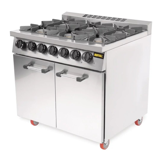
- Page 1 RANGE WITH SIX OPEN BURNER AND OVEN (GAS HEATED ) INSTALLATION, OPERATING AND MAINTENANCE INSTRUCTIONS PRODUCTION YEAR: SERIAL NO : 1783 Fourth Way, Avonmouth, Bristol BS11 8TB Published on: 09.07.2018 1/22...
-
Page 2: Table Of Contents
2. TABLE OF CONTENTS SECTION TOPICS PAGE NO. COVER PAGE TABLE OF CONTENTS INTRODUCTION TECHNICAL DATA NOZZLES,SETTINGS,GAS CATEGORIES AND PRESSURES APPLIANCE DESCRIPTION APPLIANCE LABEL DESCRIPTIONS SAFETY DETAILS BEFORE THE INSTALLATION 10-11 INSTALLATION 12-13 OPERATING THE APPLIANCE CHANGING THE INJECTOR 15-16 SERVICE OPERATIONS 17-18 CLEAN-UP AND MAINTENANCE... -
Page 3: Introduction
MAINTENANCE SERVICE FOR OUR APPLIANCES OPERATING WITH GAS MUST HAVE GAS SAFETY COMMISIONING CERTIFICATE. SPARE PARTS REQUIRED FOR THE SERVICE OF THE APPLIANCES MUST BE ORIGINAL PARTS PROVIDED BY BUFFALO OTHERWISE THE APPLIANCE WILL BE LEFT OFF OF THE WARRANTY COVERAGE. 3/22... -
Page 4: Technical Data
4.TECHNICAL DATA PRODUCT CODE 7865.N1.90739.10 MODEL CT253 MAIN DIMENSIONS (mm) 900x730x875 G20-21 mbar: 6x4,3(cook top)+6(oven)=31,8(max) HEAT POWER (KW) (H İ G31-37 mbar: 6x4 (cook top)+6(oven)=30(max) ΣQ G20-21 mbar: 6x1,43(cook top)+2(oven)=10,6(min) HEAT POWER (KW) (H İ G31-37 mbar: 6x1,33 (cook top)+2(oven)=10(min) ΣQ... -
Page 5: Nozzles,Settings,Gas Categories And Pressures
NOZZLES,SETTINGS,GAS CATEGORIES AND PRESSURES Reference Reference Oven Injector Gas Cooker Country Gas Categories Pressure(mbar) Size Injector Size I2E+ 20,0 2 mm 1,6 mm BE,FR 20,0 2 mm 1,6 mm DE,LU,PL,RO AT,CH,CZ,DK,EE,ES, FI,FR,GB,GR, HU,IE,IT,LT,LV,NL, NO,PT,RO,SE,SI,SK, I2H-20 2 mm 1,6mm HR,TR 1 mm BE,CY,ES,FI,FR,GB, I3B/P-30 29(28-30) -
Page 6: Appliance Description
5. APPLIANCE DESCRIPTION 5.1 Open burner ranges are used in kitchens of restaurants, canteens, hospitals and in catering companies etc. for cooking purposes. This device is intended for professional use only. It must be used by qualified personnel. 5.2 Before initial use of the appliance, the outer surface should be wiped with a cloth soaked in warm water and soap. -
Page 7: Appliance Label Descriptions
6. APPLIANCE LABEL DESCRIPTIONS APPLIANCE INFORMATION label # 1 INFORMATION (NATURAL GAS) (LABEL TO BE USED UPON CHANGE OF GAS SYSTEM ) APPLIANCE INFORMATION label # 2 INFORMATION (LPG) ( SECTION TO BE USED FOR CHANGE OF GAS SYSTEM) - ( See page 14 for details) Labels of the appliances operated with gas consists of two parts. -
Page 8: Safety Details
7. SAFETY DETAILS AND WARNING SIGNS SAFETY DETAILS: ☞ Do not leave the device in or exposed to direct sunlight. ☞ The appliance should only be operated under an extraction canopy in accordance with DW172(2018). ☞ If the appliance is operated with LPG, the distance between the device and LPG cylinder should be minimum 50 cm. -
Page 9: Safety Details
7. SAFETY DETAILS AND WARNING SIGNS ☞ Oil spilled during operation must be cleaned away. Otherwise this will cause slip hazard. ☞ In the event of gas leak isolate the gas and report to management for escalation. ☞ All gas connections must comply with gas safe standards. ☞... -
Page 10: Before The Installation
8. BEFORE THE INSTALLATION AVAILABILITY OF APPROPRIATE GAS INSTALLATION FOR THE APPLIANCE TO BE INSTALLED 8.1 Customer is responsible to ensure suitable for installation on their premises for appliance to be installed by gas safe certified engineer. Installation must be carried out in compliance with applicable standards. Manufacturer does not take any responsibility for any damage and error arising from transportation, installation, service and user fault. - Page 11 8. BEFORE THE INSTALLATION 8.6 PACKING Packing materials are environment friendly and can be stored without risk, disposed of in accordance to local authorities requirements. Polyethylene: wrapping, instruction booklet bag, gas nozzle bag. Polypropylene: roof packing panels, straps. Card board: corner protectors. The appliance is placed on the wooden pallet.
-
Page 12: Installation
9. INSTALLATION (Gas safe engineer only) The appliance must be installed on a sturdy and durable floor. Ensure surface is level. When appliance is in position engage brakes on castors. 9.2 Ensure 20 cm. air gap from any wall or other vertical surface . - Page 13 9. INSTALLATION (Gas safe engineer only) 9.6 After making the pipe connection gas valve is opened to allow gas to flow up to the valve. After letting gas flow in, gas leakage should be checked at gas inlet pipe connection and valve ramp connection with soap bubble method.
-
Page 14: Operating The Appliance
10. OPERATING THE APPLIANCE A- COOK TOP CONTROL KNOB B- OVEN IGNITER C- OVEN CONTROL KNOB D- HOB INDICATOR Using Top burners: Note: Pan/Pot Size-No flames should reach beyond base of pan/pot for optimum effciency. 1-Turn ‘ON’ the main gas tap. 2-Light a taper or match or have a spark producing device at hand. -
Page 15: Changing The Injector
- Mount the injector to injector connection, and screw clockwise tightly. GAS CONSUMPTION TYPE TOTAL POWER (kW) NATURAL GAS LPG ( G30 50 ) G20-21 mbar: 31,8 KW G30-37 mbar:30 KW 3,37 m³/h 2,48 kg/h CT253 TABLE : Total power and consumption data 15/22... - Page 16 11. CHANGING THE INJECTOR (Gas safe engineer only) Figure B: Changing Burner Injectors for Ovens 11.2 Changing Burner Injectors for Ovens: (Figure B) - In order to change the burner injectors, open doors of the oven and remove the base plate. -Unscrew injector connection, then unscrew the injector clockwise with an appropriate wrench and demount.
-
Page 17: Service Operations
12. SERVICE OPERATIONS (Gas safe engineer only) 12.1 TECHNICAL TROUBLESHOOTING GUIDE: Fault Possible Cause Remedy No gas supply or gas isolation Ensure that gas tanks are not empty, and gas valve is OFF. isolation valve is turned ON. Insufficient gas supply pressure. Adjust the gas supply pressure to required Main Burner standard. -
Page 18: Service Operations
12. SERVICE OPERATIONS (Gas safe engineer only) Fault Possible Cause Remedy Too much primary air. Adjust the air shutter of the burner to minimize primary air input. Wrong injector orifice size Check the orifice size of the injector installed. installed. Replace injector if necessary. -
Page 19: Clean-Up And Maintenance
13. CLEAN-UP AND MAINTENANCE CLEAN-UP: Before initial and consequent uses of the appliances, the s/s hob plate should be drained. Outer surface should be wiped with a sponge and liquid detergent. Do not use CHEMICAL CLEANING AGENTS like hydrochloric acid etc. during cleaning. MAINTENANCE : Periodic maintenance should be carried out by technical service personnel. -
Page 20: Clean-Up And Maintenance
13. CLEAN-UP AND MAINTENANCE Pressure Control 3.1. Connect rubber hose of the manometer to the manometer inlet opening. 3.2. Open main gas valve. 3.3. Start the appliance. 3.4. Read pressure gauge at the manometer. 3.5. When operating the appliance at lowest power level, read pressure gauge at the manometer (minimum power checks) 3.7. -
Page 21: Exploded View And Spare Part List
Note1: THE SETTINGS OF SPARE PARTS TO BE SUPPLIED FROM THE MANUFACTURER OR THE MANUFACTURER'S REPRESENTATIVE MUST NOT BE CHANGED. Note2: SPARE PARTS REQUIRED FOR THE SERVICE OF APPLIANCES MUST BE ORIGINAL PARTS PROVIDED BY BUFFALO OTHERWISE THE APPLIANCE WILL BE LEFT OFF OF THE WARRANTY COVERAGE. 21/22... -
Page 22: Warranty Policy Shortlist
15. WARRANTY POLICY SHORTLIST IMPORTANT INFORMATION WARRANTY POLICY SHORTLIST Warranty does not cover: correcting faults caused by incorrect installation of a product where an engineer cannot gain access to a site or a product repeat commission visits replacement of any parts where damage has been caused by misuse engineer waiting time will be chargeable routine maintenance and cleaning gas conversions (e.g.
Need help?
Do you have a question about the CT253 and is the answer not in the manual?
Questions and answers