Table of Contents
Advertisement
Quick Links
Advertisement
Table of Contents

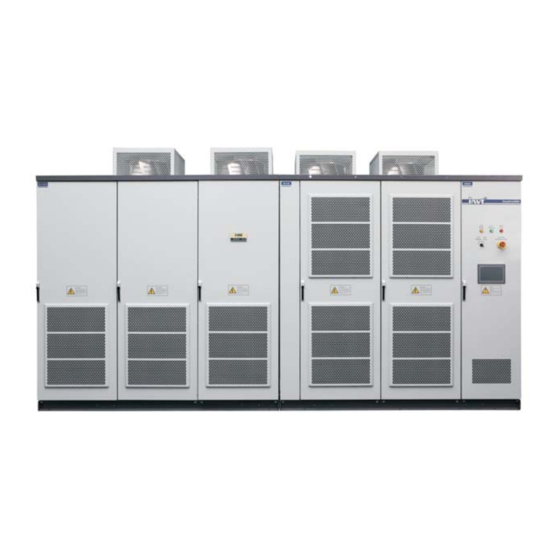
Summary of Contents for INVT Goodrive5000 Series
- Page 1 Goodrive5000 Series Medium Voltage Variable Frequency Speed Control System...
- Page 12 GD5000-A□□□□-□□-X X X X ⑤ ⑥ ⑦ ⑧ ② ③ ① ④ Lot number Lot number Lot number Lot number Voltage degree Rated capacity Product type Name of medium voltage series products...
- Page 13 GD5000 Medium Voltage Variable Frequency Speed Control System Product Model Rated Capacity Rated Motor Power Rated Input Voltage Rated Output Current Rated Input Frequency 47~60Hz Rated Output Voltage ≥0.96 Output Frequency Range 0~120Hz Rated Input Power Factor IP Grade Manufacture Date MADE IN CHINA...
- Page 22 Bypass contactor User AI/AO/SI/HDI/HDO User RO terminal area terminal area Relay area J3 J4 Connecting finger of user I/O board...
- Page 23 Switch cabinet Switch cabinet 0 control board 0 Switch cabinet Switch cabinet 1 control board 1 Switch Main control cabinet System IO board board control fiber Switch cabinet Switch cabinet 2 control board 2 Switch cabinet Switch cabinet 3 control board 3...
- Page 27 Goodrive5000 User switch QF series products Motor User switch QF Goodrive5000 series products Motor...
- Page 28 Output copper bar Optical fiber port Input copper bar Name plate Fault indicator light Running indicator light Ready indicator light Remote/Local Emergency stop button Touch screen Alarm buzzer...
- Page 30 State displaying Control region parameters Control Function command buttons (extended) Data displaying Control region command (common) Function buttons...
- Page 38 Goodrive5000 User switch QF series products Motor...
- Page 41 Goodrive5000 series medium voltage variable frequency speed control systems Transformer Input terminals Power unit of main circuit Grounding resistance below 10Ω Input terminals of control circuit Fan power AC 380V (3-phase 4-wire) Control power High-speed pulse input Analog output 1...
- Page 47 Keypad setting Set frequency A frequency setting Actual set frequency Multi-step speed up/down setting B frequency setting MODBUS setting Fieldbus setting Max frequency Set frequency of A channel Percentage of B frequency setting...
- Page 49 Output frequency Time Actual ACC time Actual DEC time Set ACC time Set DEC time...
- Page 51 Output frequency Time f1 is set by P1.02 t1 is set by P1.03...
- Page 53 Output frequency f ACC/DEC time 1= ×P1.07 2= ×P1.08 Accelerated speed Change rate of accelerated speed...
- Page 54 Output frequency Target frequency DC braking frequency at stop Starting frequency 1 DC braking time before starting Output voltage 2 hold time of starting frequency 3 ACC time 4 DEC time 5 waiting time before stop braking 6 stop DC braking time DC braking DC braking t4 t5...
- Page 55 Output frequency Dead time FWD running Time REV running...
- Page 60 PI parameters (P3.00, P3.01) (P3.03, P3.04) Output frequency f P3.02 P3.05...
- Page 62 Output voltage 1.3 power low torque V/F curve 1.7 power low torque V/F curve Linear type 2.0 power low torque V/F curve Square type Output frequency Output voltage boost Output frequency cut-off...
- Page 63 Output voltage 100% V Output frequency...
- Page 64 t1=P4.14 t2=P4.15...
- Page 68 Buffer resistance Inverter The dotted box stands for switch cabinet.
- Page 72 Running command running Action GD5000 running Stop Running command Action No action running GD5000 No action Action running Stop...
- Page 73 Corresponding setting AI value...
- Page 80 Corresponding setting...
- Page 81 AO1 output P6.32 P6.30 Corresponding setting (0.00V) P6.29 P6.31 100%...
- Page 84 Set frequency f 1/2* jumping range Jumping frequency 2 1/2* jumping range 1/2* jumping range Jumping frequency 1 1/2* jumping range Time t...
- Page 85 Output frequency FDT electrical level FDT retention Time t Time t Output frequency f Detection range Set frequency Time t Time t...
- Page 86 Motor torque With dropping control Rated torque Without dropping control Synchronous rotating speed Motor rotating speed...
- Page 93 Output frequency frequency PID preset value PID control Control algorithm (percentage) (percentage) Filter Feedback value...
- Page 96 P10.12 Feedback value Reference value P10.11 Time t Output frequency Time t...
- Page 97 Deviation limit Feedback value Reference value Time t Output frequency Time t...
- Page 102 Feedback value Deviation limit Reference value Time t Output frequency Time t...
- Page 106 DC bus voltage Overvoltage speed loss point Time t Output frequency Time t Output current Overcurrent speed loss point Time t Output frequency Set frequency Constant speed Time t...
- Page 116 Parameter identification (PKW) Process data (PZD) Fixed area Free distributed area PZD2 PZD3 PZD12 PKW1 PKW2 PKW3 PKW4...
- Page 134 Corresponding 100.0% setting P5.34 P5.24 AO1 output AI value P6.32 P5.21 P5.23 (20mA) (0mA) AI1/AI2 P5.22 P6.30 Corresponding setting (0.00V) P6.29 P6.31 100% -100.0%...
- Page 135 Output voltage boost Output frequency cut-off...
- Page 141 Bypass cabinet...
- Page 142 QS1, QS2 and QS3 in close state; switch cabinet is ATS Synchronous switching enabling when the inverter runs to 50Hz at variable frequency Send the command of variable frequency switching into power frequency The inverter performs phase lock for power frequency power supply Fail...
- Page 152 Hoisting location mark ≥1.2m Medium voltage large power inverter...
- Page 153 ≥0.5m Side Side Center of Center of Fender Gravity Gravity Forklift Forklift...
- Page 158 Centrifugal fan Centrifugal fan Power unit Power unit Power unit Air duct...
- Page 215 6 6 0 0 1 - 0 0 1 6 4 201811 (V1.3)


Need help?
Do you have a question about the Goodrive5000 Series and is the answer not in the manual?
Questions and answers