
Related Manuals for Audio Weaver STM32F4 Series

Summary of Contents for Audio Weaver STM32F4 Series
- Page 1 STM32 F4xx Discovery Board Setup Guide Audio Weaver November 2016...
- Page 2 DSP Concepts STM32F4xx Discovery Board Users Guide Copyright Information © 2014 DSP Concepts, Inc., ALL RIGHTS RESERVED. This document may not be reproduced in any form without prior, express written consent from DSP Concepts, Inc. Printed in the USA. Disclaimer DSP Concepts, Inc reserves the right to change this product without prior notice.
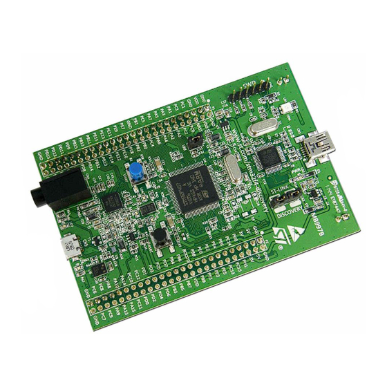
- Page 3 Overview This document describes how to use Audio Weaver with the STM32F401 and F407 Discovery boards. These are low cost evaluation boards for the STM32F4 series of Cortex-M4 processors. The two boards differ slightly in the operating frequency and amount of memory available. The instructions show how to setup the F407 board - the higher performance processor.
- Page 4 DSP Concepts STM32F4xx Discovery Board Users Guide Setup The board has two USB connections: Mini-USB – for power and programming Micro-USB – for audio and control Start by connecting the mini-USB connector to your PC. This will power on the board and several LEDs will light.
- Page 5 DSP Concepts STM32F4xx Discovery Board Users Guide Click on the “Full Chip Erase” button to completely erase the flash contents. Then Click on the “Program and Verify” button: Then browse and select a binary loader file to program. Each Discovery board has a separate .bin file: <AWE>/Bin/STM32-keil-rel/STM32F401VC.bin <AWE>/Bin/STM32-keil-rel/STM32F407VG.bin...
-
Page 6: Connecting Audio Weaver To The Target
You should hear audio being rendered by the STM32 Discovery board. Connecting Audio Weaver to the Target Launch Audio Weaver Designer application. Then from the Server Window (not from the Designer window) select the menu item TargetChange Connection Windows XP is currently not supported. - Page 7 DSP Concepts STM32F4xx Discovery Board Users Guide In the droplist select “USB” and change the PID and VID settings if necessary as shown below For the STM32F407 board For the STM32F401 board Click on the “Change” button. This window will dismiss and the Server window will update to reflect the connection to the Discovery board.
-
Page 8: Using Gpio Inputs And Outputs
DSP Concepts STM32F4xx Discovery Board Users Guide At this point the Audio Weaver Server is able to communicate with the board. To make sure that the Audio Weaver Designer sees this change, click on the “Reconnect to Server” button The default system drawn in Audio Weaver Designer is shown below. - Page 9 DSP Concepts STM32F4xx Discovery Board Users Guide STM32F407VG-Discovery Board Available GPIO Pin Map GPIO Block Board Input Pin Board Output Pin Pin Number Name Name Blue User Button LED6 LED3 LED5 PA15 PA15 PB11 PB12 PB13 PB11 PB14 PB12 PB15 PB13 PB14 PB15...
- Page 10 DSP Concepts STM32F4xx Discovery Board Users Guide PE10 PE11 PE12 PE10 PE13 PE11 PE14 PE12 PE15 PE13 PE14 PE15 Page: 10 of 10...
Need help?
Do you have a question about the STM32F4 Series and is the answer not in the manual?
Questions and answers