Advertisement
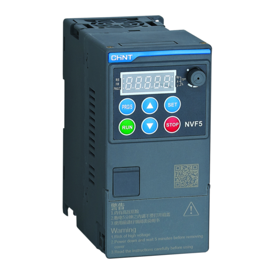
NVF5 Series Inverter Quick Start-Up Wizard
1.Safety Precautions
The purpose of this quick start-up wizard is to guide you
to complete the basic installation 、 wiring and basic
parameters setting、commissioning and troubleshooting for
NVF5 series inverter products. For more information, please
refer to the user manual or scan the QR code to get the user
materials. This NVF5 series products have been strictly
tested and packaged before leaving the factory. If abnormal
information such as inverter damage and wrong delivery is
found, please contact Chint channel or the relevant office
or call Chint oversea hotline:400-1177-797
Attention:
It is not permitted to conduct unauthorized modification in case of the danger of
fire/electric shock and other hurt!
Installation must be conducted by qualified personnel in case of the danger of
electric shock!
Please install the inverter on the metal equipmen(supplementary enclosure) or
other non-combustible objects in case of the danger of fire!
It is not permitted to place combustibles nearby in case of the danger of fire!
The products should be installed with either fuses or an input circuit breaker
between the inverter and power supply in case of danger of fire!
Danger
It is not permitted to install the inverter in an environemnt containing explosive
gases in case of the danger of explosion!
It is not permitted to insall the inverter at a place directly exposed in sunlight in
case of the danger of equipment damage!
It is not permitted to install the inverter on occasions where water splashing in
case of the danger of equipment damage!
Installation Dimensions:
Figure 1-1
Figure 1-2
Advertisement
Table of Contents

Summary of Contents for CHINT NVF5 Series
- Page 1 、 wiring and basic parameters setting、commissioning and troubleshooting for NVF5 series inverter products. For more information, please refer to the user manual or scan the QR code to get the user materials. This NVF5 series products have been strictly tested and packaged before leaving the factory.
-
Page 2: Installation And Wiring
2.Catalog Number Description、Product Models、Dimensions and Weights NVF5 Number of Inverter Input Product Applicable T: Universal Input Voltage Brake Unit Phases Model Motor Power Model Rating B: Standard (kW) D: Single 2:230V Embedded Phase 4:380V~ 440V Blank: No S: Three Embedded Phases NVF5-0.4/TD2~NVF5-2.2/TD2、NVF5-0.4/TD2-B~ NVF5-3.7/TS4-B~NVF5-7.5/TS4-B... -
Page 3: Analog Voltage Output
(1) Single Phase 230V (NVF5-0.4/TD2~2.2/TD2 (2) Three Phase380V (NVF5-0.4/TS4-B~ and NVF5-0.4/TD2-B~2.2/TD2-B) 7.5/TS4-B) NVF5-0.4/TD2~2.2/TD2 and NVF5-0.4/TS4-B~7.5/TS4-B NVF5-0.4/TD2-B~2.2/TD2-B Power Terminal Power Terminal Figure 3-1 Figure 3-2 Terminal Name Description Main Power Supply The three-phase AC input terminals ,connecting R、S、T Input with the power grid Main Power Supply The Single-Phase AC input terminals ,connecting L1、L2... -
Page 4: Integral Keypad
Wiring Demonstration: 4.Integral Keypad 4.1 Integral Keypad and Indicators... -
Page 5: Simple Parameter Menu And Commissioning Process
Figure 4-1 4.2 Combination key Function Description Description Parameter Menu Mode Selection(F7.11) 1、 Simple Parameter Menu Mode(U-1) + 2、 Custom Parameter Menu Mode(U-2) 3、 Engineering Parameter Menu Mode(U-3) The system is under the main Lock Combinational Key interface + In custom menu mode,in menu level Add custom parameters The system is under the main Unlock Combinational Key... - Page 6 0:Integral Keypad 1:Digital Terminal Command ○ F0.01 Source 2:Communication 3:Remote Panel 0:Digital Given 1:AI1 2:AI2 3:Reserve Main 4:High Speed Pulse HDI Reference ○ F0.02 Frequency 5:Preset Speed Reference Reference 6:Simple PLC Reference 7:Close Loop PID Reference 8:Reserve 9:Potentiometer Reference ○ F0.09-Min.
- Page 7 6. Fault description and Trouble shooting If a fault appears, Please see for an explanation of the fault code and check by yourself firstly before asking for help from Chint or Chint channels.When you need support,please contact Chint or Chint channels.
- Page 8 Lower ambient temperature lose-phase and other reasons Check wiring and re-wire Aux. power supply damage, Checking wiring drive voltage undervoltage Asking for Chint technical support IGBT Module Damage Control Board Abnormal Heat Sink High ambient temperature E.OH1 Lower ambient temperature...


Need help?
Do you have a question about the NVF5 Series and is the answer not in the manual?
Questions and answers