Table of Contents
Advertisement
Quick Links
Advertisement
Table of Contents

Related Manuals for Power Soak Produce Soak


Summary of Contents for Power Soak Produce Soak
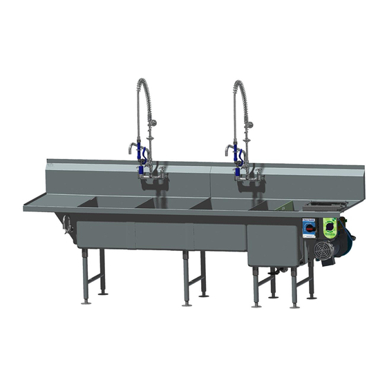
- Page 1 Owner's Manual Produce Soak – Fry Wash...
-
Page 2: Table Of Contents
Placing the Wash Components .... Error! Bookmark not defined. Rib sets .................... 7 Partitions .......... Error! Bookmark not defined. Flow Guides ........Error! Bookmark not defined. Filling the Produce Soak ... Error! Bookmark not defined. Washing Tips ................. 19 Emptying the Produce Soak ..Error! Bookmark not defined. -
Page 3: Introduction And Conventions
Introduction and Conventions Produce Soak – Fry Wash... -
Page 4: Product Introduction
Every system is manufactured to last, with only high-quality, heavy-duty, 14 gauge stainless steel used in its construction. All electrical components used in a Produce Soak system are of the highest quality. The faucet and drain are designed for quick filling and emptying of the system's sink. -
Page 5: Explanation Of Warning Messages
Children must not be allowed to play in the sinks, on countertops or with the controls of the Power Soak equipment. Cleaning or use of this machine must not be done by children without super vision. This machine can be used by children... - Page 6 - -This page left intentionally blank - -...
-
Page 7: Operating Instructions
Operating Instructions Produce Soak – Fry Wash... -
Page 8: Preparing The Produce Soak
Preparing the Produce Soak Installing the Potato Cutter The potato cutter is not manufactured by Power Soak and must be purchased from another source. Power Soak does provide a mounting bracket for attaching the potato cutter to the drain board of the Produce Soak. -
Page 9: Rib Sets
The potato cutter assembly is attached to the drain board with the mounting bracket using the studs that are located on the wash tank drain board. Place the rubber mounting pads over the studs, one on the front studs and one on the rear studs. Position the mounting bracket and cutter so that the large opening on the bottom of the bracket aligns with the head of the stud and lower the bracket over the stud, pressing the cutter and bracket onto the rubber pads. - Page 10 To remove the cutter, lift on the tab at the rear of the cutter and slide the mounting bracket away from the wash sink Lift on the tab and slide the cutter away from the wash sink to remove it from the drain board.
- Page 11 Installing the Components in the Wash Sink Before installing the components in the wash sink, inspect the sink, the channel in the back wall and all of the components to be sure they are clean and free of debris. Installing the Intake Screen The intake screen is removable for cleaning.
- Page 12 Rotate the screen into position against the back wall and resting on the bottom of the sink. The illustration shows a “Left Hand” machine, a “Right Hand” machine will insert into the opening on the opposite side of the machine. Installing the Jet Channel The jet channel must be installed before starting the wash pump.
- Page 13 Rotate the jet channel into the opening. Slide the jet channel until the short flat section is tucked behind the sheet metal. Instructions for installing the jet channel are imprinted on the face of the jet channel. These instructions outline the same procedure that is printed in this section of the manual.
- Page 14 Place the front rib sets against the front wall of the sink. Leave a finger- size gap between the rib sets in order to insert the divider board between the rib sets. Divider Board Insert the divider board into the gap between the front and rear pairs of rib sets.
-
Page 15: Flow Guides
Flow Guides The flat perforated sheets of plastic are the flow guides that direct the water flow in a circular motion around the interior of the sink. The circular motion of the water moves the fries to clean the surface of the pieces. Lay the flow guide on the rib set and slide it under the hooked ends of the corner ribs. - Page 16 Wave Guide The last step of the sink component installation is to place the wave guide sheet metal on top of the front rib set. This piece is used to prevent the fries from falling down between the flow guide and the front wall of the sink. Slide the back surface along the front wall of the sink, between the front rib set and the sheet metal wall of the sink.
- Page 17 Filling the Wash Sink The amount of water that is run into the wash sink will be dependent on the amount of potatoes that are placed in the sink. Start by filling the sink approximately half full of water. Limit the volume of potatoes that will be placed into both sections of the sink to 50 pounds or less.
- Page 18 Washing Sliced Potato Fries The wash sink must be filled prior to starting the wash pump motor. The motor is operated directly by an “ON – OFF” selector switch. Turn the switch to the ON position to start the pump. When the pump is running, the water will become turbulent, and begin rotating the potatoes from front to back.
- Page 19 Do not place knives or other sharp objects in the Produce Soak. Allowing knives or other sharp objects to tumble freely in the Produce Soak tank may cause damage to the equipment and bodily injury to the user. The fries should be allowed to rotate in the wash sink for a time that is determined by the management of the store (usually 3 to 5 minutes).
- Page 20 When all of the fries have been removed from the wash sink, turn the wash pump motor off by rotating the control handle to the “OFF” position. Drain Valve The drain valve handle rotates ¼ turn to open or close the drain valve. Counterclockwise rotation will open the drain valve;...
-
Page 21: Washing Tips
Washing Tips In order to get the most effective results, follow the suggested tips: Always use cold water to fill the wash sink Load each section of the wash sink with approximately the same amount of fries Do not exceed 25 pounds of potatoes in each section of the wash sink ... - Page 22 End of Operation Cleaning After the last batch of fries has been washed, the Produce Soak needs to be disassembled and thoroughly cleaned. A recommended cleaning procedure is included in this section. This procedure was determined for general operation. Each owner of the Produce Soak may have specific needs that have been outlined in their own procedure that will supersede these instructions.
- Page 23 Pump Purge Procedure...
- Page 24 - -This page left intentionally blank - -...
-
Page 25: Preventive Maintenance
Preventive Maintenance Produce Soak – Fry Wash... - Page 26 The following tasks should be completed on a routine basis to ensure that the system remains reliable. Turn off the power to the Produce Soak at the main breaker prior to working on the Produce Soak pump or motor.
-
Page 27: Troubleshooting
Troubleshooting Produce Soak – Fry Wash... - Page 28 Circuit breaker tripped Investigate reason for tripping, e.g. damaged wiring, undersized breaker. CONTACT POWER SOAK SERVICE OR AN AUTORIZED SERVICE AGENCY. Motor thermal Investigate reason for overload tripping, overload tripped e.g. debris stuck in pump impeller. If debris...
- Page 29 Remove debris from the impeller and reassemble. CONTACT POWER SOAK SERVICE OR AN AUTORIZED SERVICE AGENCY for this service. Motor is running on Confirm that the house wiring supply is the wrong voltage appropriate for the motor nameplate data.
- Page 30 Slide the motor, adapter plate, and impeller running out of the pump housing. Remove debris (cont’ed) from the impeller and reassemble. CONTACT POWER SOAK SERVICE OR AN AUTORIZED SERVICE AGENCY for this service.
- Page 31 - -This page left intentionally blank - -...
-
Page 32: Installation
Installation Produce Soak – Fry Wash... -
Page 33: Electrical Requirements
They are also shown inside the control panel enclosure itself. All Produce Soak systems have a single point electrical connection, and a dedicated circuit is required. The system is completely pre-wired and tested at the factory, and a hard- wired connection from an appropriate power source is all that is required. -
Page 34: Plumbing Requirements
If your system is a “left-to-right” unit, you should locate the disconnect at the left end of the system. (The opposite would be true for a “right-to-left” system.) Ideally, the disconnect should be located on the wall directly behind the pump motor and control panel provided this location is easily accessible by the operator and does not interfere with the faucet. - Page 35 Power Soak and Produce Soak are registered trademarks of Cantrell Industries, Inc. The Produce Soak design and concept are fully patented. Power Soak Systems. Inc. 903 East 104 Street, Suite 130 Kansas City, MO 64131 Phone (816) 761-3250 Fax (816) 761-0544 (800) 444-9624 www.powersoak.com...
Need help?
Do you have a question about the Produce Soak and is the answer not in the manual?
Questions and answers