
Summary of Contents for INNO USB-CAN MODULE
- Page 1 Design Service,Production Service www.inno-maker.com USB-CAN MODULE User Manual Support: support@inno-maker.com www.inno-maker.com/wiki Bulk Price: sales@inno-maker.com...
-
Page 2: General Description
Design Service,Production Service www.inno-maker.com General Description: USB-CAN module is a “plug and play ” and bi-directional port powered USB to CAN converter which realizes long-distance communication between your Raspberry Pi and other devices stably though CAN- Bus connection. With small size and convenient operation, It’s a cost-effective solution that are safe and reliable... -
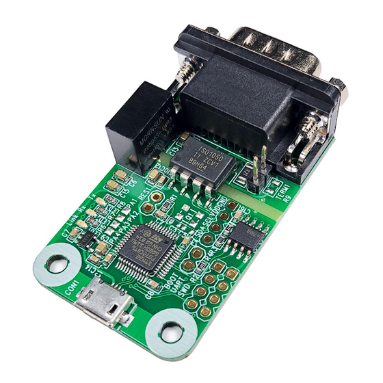
Page 3: Hardware Description
Design Service,Production Service www.inno-maker.com Hardware Description 1. Pin Out Configuration 2. 120 Ohm resistor setting. Disable 120 Ohm resistor. Enable120 Ohm resistor. Support: support@inno-maker.com www.inno-maker.com/wiki Bulk Price: sales@inno-maker.com... -
Page 4: Software Description
1. CAN Communication Test Demo Run demo for two Raspberry Pi: (1) Prepare two USB-CAN module and two Raspberry Pi board. Connect the H and L port of USB-CAN module to other’s port, and then insert into the USB Host of Raspberry PI board. - Page 5 Design Service,Production Service www.inno-maker.com (6) Set other Pi as sender, execute following commands. ./can0_send (7) You should see that the receiver has received the packet. Support: support@inno-maker.com www.inno-maker.com/wiki Bulk Price: sales@inno-maker.com...
- Page 6 Run demo for only one Raspberry Pi: In this case, you also can insert two USB-CAN module into a Raspberry PI board to test. You should see two can socket “can 0” and “can 1” devices. So notice that you need to modify the code to change “can 0”...
- Page 7 Note :You must use a TF card at least than 16Gb, Otherwise it will write failed. (2) For Sender’s code: Step 1: Create the socket, If an error occurs then the return result is -1. Support: support@inno-maker.com www.inno-maker.com/wiki Bulk Price: sales@inno-maker.com...
- Page 8 Step 2: Locate the interface to “can0” or other name you wish to use. The name will show when you execute “./ifconfig –a”. Step 3: Bind the socket to “can0”. Step 4: Disable sender’s filtering rules,this program only send message do not receive packets. Step 5: Assembly data to send. Support: support@inno-maker.com www.inno-maker.com/wiki Bulk Price: sales@inno-maker.com...
- Page 9 Step 6: Send message to the can bus.You can use the return value of write() to check whether all data has been sent successfully . Step 7: Close can0 device and disable socket. (3) For Receiver’code: step 1 and step 2 is same as Sender’s code. step 3:It’s different from Sender’s. Support: support@inno-maker.com www.inno-maker.com/wiki Bulk Price: sales@inno-maker.com...
-
Page 10: Version Descriptions
If you have any suggestions,ideas, codes and tools please feel free to email to me. I will update the user manual and record your name and E-mail in list. Look forward to your letter and kindly share. Support: support@inno-maker.com www.inno-maker.com/wiki Bulk Price: sales@inno-maker.com...
Need help?
Do you have a question about the USB-CAN MODULE and is the answer not in the manual?
Questions and answers