Table of Contents
Advertisement
Quick Links
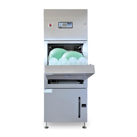
Bedpan/Urinal Bottle and Utensil/Bowl
Operation, Maintenance and
design and technical specifications are subject to change without notice.
Serial Number:
Date Installed:
Issue 11
Washer Disinfector
Models WDS1; WDS3
Installation Manual
Note: Due to Malmet's Policy of continuous product improvement;
Supplied to:
Installed by:
Head Office and Customer Service
ABN 95 001 717 791
9-11 McKay Avenue
PO Box 373
Leeton NSW 2705
Phone: +61 2 6953 7677
Email: info@malmet.com.au
Advertisement
Table of Contents

Related Manuals for Malmet WDS Series


Summary of Contents for Malmet WDS Series
- Page 1 Bedpan/Urinal Bottle and Utensil/Bowl Washer Disinfector Models WDS1; WDS3 Operation, Maintenance and Installation Manual Note: Due to Malmet’s Policy of continuous product improvement; design and technical specifications are subject to change without notice. Serial Number: Supplied to: Date Installed: Installed by:...
-
Page 2: Table Of Contents
Operation, Maintenance and Installation Manual Table of Contents Foreword ................................... 2 Certifications and Compliances ............................2 Quality Policy ..................................2 Safety Instructions ................................3 Design Parameters ..............................4 Operating Cycles ............................4 1. 2 Detergent ..............................5 Device Features ............................6 Control LCD Display Features ........................ -
Page 3: Foreword
Quality Policy Malmet (Australia) Pty Ltd is Quality Certified to ISO 13485; ISO 9001; AS 3902; NZS 9002 and guarantees the quality of this device. Should you have any problems with your device, contact the company from whom you purchased it, or Malmet (Australia) Pty Ltd. -
Page 4: Safety Instructions
Operation, Maintenance and Installation Manual Safety Instructions WARNINGS Be aware of 240V / 415V Voltage Disconnect power when servicing Mains power ISO switch must be in an accessible position so device can be isolated from mains power during service Be aware of steam discharge Utensils and racks are hot to handle Safety gloves and goggles must be worn when changing detergent Safety clothing with reflective tape can activate the hands free sensor when... -
Page 5: Design Parameters
Operation, Maintenance and Installation Manual 1.0 Design Parameters The Malmet Bedpan/Urinal Bottle and Utensil/Bowl Washer Disinfector has been designed within the following parameters Operating Cycles Three available operating (cleaning and disinfection) Urinal Bottle / Bedpan Load: capacity: 2 x small slipper pans, 2 x large slipper pans, 2 x standard bedpans and 4 x standard male and... -
Page 6: Detergent
Operation, Maintenance and Installation Manual 1. 2 Detergent The 5 litre detergent container is accessed by opening the bottom door. Only use Malmet approved detergent (See technical data for detergent details) Pull handle on detergent door and open Unscrew cap and pull out with suction hose (let hose hang in detergent chamber) -
Page 7: Device Features
Operation, Maintenance and Installation Manual Device Features Control panel with LCD display USB port Emergency cycle stop Wash Chamber Bowl / Utensil rack, hinged Bedpan rack, hinged Urinal bottle rack Door Auto open and close Detergent access door Control LCD Display Features Issue 11 Page 6 14/02/2019... -
Page 8: Operating Features
Operation, Maintenance and Installation Manual Operating Features POWER On/Off Standby HANDS FREE SENSOR For hands free opening, closing door and starting of cycle. To operate, hold hand in front of sensor URINAL BOTTLE ONLY Select and start for urinal bottle only cycle BOWL / UTENSILS Select and start for bowls / kidney dishes etc URINAL BOTTLE / BEDPAN... -
Page 9: Installation And Commissioning
Operation, Maintenance and Installation Manual 2.0 Installation and Commissioning Installation Before unpacking device inspect carton for any damage relating to forklift forks and damage relating to device falling over or for evidence of top loading Remove carton from device; inspect all external panels for damage Warning - Device Weight ... - Page 10 Operation, Maintenance and Installation Manual Service Connections MODEL HOT WATER COLD WATER SOIL LINE ELECTRICAL 240V 100mm ‘S’ or ‘P ’Trap WDS1 Solenoid valve GB¾ Solenoid valve 1 Phase Hot water discharge (1ph) Male GB¾ Male 20 Amps 75-80°C 50 Hertz 415V 100mm ‘S’...
-
Page 11: Service Connection And Layout Details
Operation, Maintenance and Installation Manual Service Connection and Layout Details Issue 11 Page 10 14/02/2019... -
Page 12: Plumbing
Level the device by using the flanged screw in legs and if possible maintain approx. 100mm floor clearance for ease of floor cleaning. Malmet recommends affixing some of the leg flanges to the floor via stainless self-tapping screws to prevent sideways movements and damage to services and soil line connections ... -
Page 13: Electrical
Mains power ISO switch must be in an accessible position so device can be isolated from mains power during service Malmet recommends having a 30mA RCD in the mains supply fixed wiring If the supply cord is damaged, it shall be replaced by the manufacturer or its service agent or similarly qualified person in... -
Page 14: Loading And Operating
Operation, Maintenance and Installation Manual 3.0 Loading and Operation Urinal Bottle / Bedpan – Loading Refer to laminated WDS Instructions To open door, use or press Place racks into the correct positions Check that bowl Lift bedpan rack up and lock rack is in the up into position. -
Page 15: Urinal Bottle / Bedpan - Operating Cycle
Operation, Maintenance and Installation Manual Urinal Bottle / Bedpan – Operating Cycle Refer to laminated WDS Instructions Open door, use or press Select URINE / BEDPAN cycle by adjusting the rack position as shown Close door, use the or press When the door closes, to start cycle use the or press whilst “START”... -
Page 16: Urinal Bottle Only - Loading
Operation, Maintenance and Installation Manual Urinal Bottle Only – Loading Refer to laminated WDS Instructions Open door, use or press Place racks into correct positions Bedpan rack must be in Check that the bowl the down position rack is in the up position Place urinal bottles into rack Issue 11... - Page 17 Operation, Maintenance and Installation Manual Urinal Bottle Only – Operating Cycle Refer to laminated WDS Instructions Open door, use or press Select URINE / BEDPAN cycle by adjusting the rack position as shown Close door, use or press When the door closes, to start the cycle use or press whilst “START’...
-
Page 18: Bowl / Utensil - Loading
Operation, Maintenance and Installation Manual Bowl / Utensil - Loading Refer to laminated WDS Instructions Open door, use or press Place racks into the correct positions Place bedpan rack Place the bowl into the down rack in the down position position Examples of bowls and utensils placed onto racks Large and medium size bowls... -
Page 19: Bowl / Utensil - Operating Cycle
Operation, Maintenance and Installation Manual Bowl / Utensil – Operating Cycle Refer to laminated WDS Instructions Open door, use or press Select URINE / BEDPAN cycle by adjusting the rack position as shown Close door, use or press When the door closes, to start the cycle use or press whilst “START’... -
Page 20: Cycle Of Operation
Operation, Maintenance and Installation Manual 4.0 Cycle of Operation 1. Press POWER ON button; display shows: POWER POWER After short delay display shows alternating OPEN OPEN-DOOR DOOR 2. Open door; display shows: OPENING OPENING 3. When door is open; display shows: LOAD ITEMS LOAD-ITEMS... - Page 21 Operation, Maintenance and Installation Manual 4. After select cycle; display shows: BEDPAN/URINE BOTTLE URINE ONLY OR BOWL CLOSING CLOSING CLOSING Cycle begins, to cancel press door button 5. Once door is closed (using Hands Free or door button only); display shows ‘START’ for 10 seconds START START START...
- Page 22 Operation, Maintenance and Installation Manual CYCLE 3: HOT WASH PLUS DETERGENT CYCLE 2: HOT WASH PLUS DETERGENT Display shows: HOT+DET HOT+DET FILL 3 FILL 2 HOT+DET-FILL 2 HOT+DET-FILL 3 When filled to correct level; display shows: HEATING HEATING HEATING- WATER HEATING-WATER 2 WATER 3 WATER 2...
- Page 23 Operation, Maintenance and Installation Manual 7. Disinfection; display shows: TEMP 50° to 93°C TEMP 50°C Steam heating chamber to 93°C TEMP 50°C When chamber reaches 93°C Disinfection for 1 min @ 93°C TEMP 93°C TEMP 93°C TEMP 95°C When disinfection completes; display briefly shows: SUCCESS SUCCESS SUCCESS...
- Page 24 Operation, Maintenance and Installation Manual To close door without running cycle After the door is opened; display shows: LOAD ITEMS Then SELECT CYCLE Manually press DOOR button Software will check that racks are in correct position before door closes. If racks have been moved, ‘WRONG RACK’ will flash. Place rack or racks into correct position for any of the 3 cycles and press DOOR button ...
-
Page 25: Detergent Warnings
Operation, Maintenance and Installation Manual Detergent Warnings First Warning When last full segment is showing, ‘LOW DETERGENT’ will flash (there is approx. 1.5 to 1.6 litres in bottle) Second Warning When no full segments are showing ‘EMPTY DETERGENT’ will flash, there is approximately 750mL to 1litre in bottle Third warning Fault 302 - detergent time out (no detergent in bottle) When full bottle is installed the detergent line will require purging (see 5.7) -
Page 26: Maintenance
The Malmet Bedpan/Urinal Bottle and Utensil/Bowl Washer Disinfector is self-cleaning; however, proper care should be taken to ensure that the device is cleaned and maintained in accordance with maintenance instructions for Malmet Bedpan/Urinal Bottle and Utensil/Bowl Washer Disinfector, regulatory and common sense practices. -
Page 27: Recommended Preventative Maintenance Schedule
15. Replace battery on processor PCB every 12 months. Check time and date, adjust if required Malmet will make available on request circuit diagrams, component parts lists, descriptions, calibration instructions, or information which will assist the user’s appropriately qualified technical personnel to repair those parts of the device... -
Page 28: Fault Codes
Operation, Maintenance and Installation Manual Fault Codes The device is controlled by a sophisticated micro-processor. The processor has fault detection capability and indicates faults by code on the LCD display as well as an audible buzzer Software V4.02 FAULT STATE DESCRIPTION POSSIBLE CAUSES CODE... - Page 29 Operation, Maintenance and Installation Manual FAULT STATE DESCRIPTION POSSIBLE CAUSES CODE Cold Wash Run Low Water Level during wash Low pump water flow, blocked spray nozzles, Faulty solenoid, Panel lockout switches J8 open circuit. Faulty level probe. Incorrect spray nozzles fitted Cold Wash Run Door Open Door opened during wash cycle, faulty door...
- Page 30 Operation, Maintenance and Installation Manual FAULT STATE DESCRIPTION POSSIBLE CAUSES CODE Hot Rinse Run Door Open Door opened during wash cycle, faulty door interlock switch J11 J10 Hot Rinse Run Pump run without solenoid Check Cycle Times parameters, Faulty solenoids Hot Rinse Run Timeout before Level reached Low pump water flow, blocked spray nozzles,...
-
Page 31: Purge Reset (Operator)
Operation, Maintenance and Installation Manual Purge Reset (Operator) Turn power OFF at control LCD display Turn power ON at control LCD display The display will alternate between the current fault/s and “PURGE”, press SELECT to start the Purge Reset cycle When purge is complete the previous cycle will automatically start to ensure the load is disinfected If the fault reoccurs contact maintenance or service provider Purge Detergent Line (Operator) -
Page 32: Purge Reset (Maintenance)
Operation, Maintenance and Installation Manual Purging must only be undertaken by Malmet service personal of Malmet trained facility maintenance personal. Purge Reset (Maintenance) Turn power OFF at control LCD display Turn power ON at control LCD display Hold down both SCROLL... -
Page 33: Detergent Level And Load Cell Calibration
Operation, Maintenance and Installation Manual Detergent Level and Load Cell Calibration 1. INSERT empty detergent bottle and also suction hose. Also make sure that the bottle is centrally located over the sensor plate. Check that the supporting plate is correctly located and is not obstructed by the detergent hose and can pivot freely 2. -
Page 34: Device Service Component Identification And Part Listing
Operation, Maintenance and Installation Manual 5.10 DEVICE SERVICE COMPONENT IDENTIFICATION AND PART LISTING L/H SIDE VIEW R/H SIDE VIEW REAR VIEW FRONT VIEW Issue 11 Page 33 14/02/2019... - Page 35 Operation, Maintenance and Installation Manual ELECTRICAL 1 PH COMPONENTS 3 PH COMPONENTS TOP VIEW SPRAY LOCATIONS Issue 11 Page 34 14/02/2019...
- Page 36 Operation, Maintenance and Installation Manual Item Description Item Description Water tank assembly 92-4019 (for 1 Ph device) 5 level probe assembly (water tank) 92-4075 Water tank assembly 92-4056 (for 3 Ph device) CW/HW in line assembly 92-4041 Chamber assembly 92-4001 Lid lockout sw assembly 92-4086 Spray line top assembly...
-
Page 37: User Menu And Test Mode
Operation, Maintenance and Installation Manual 5.11 User Menu and Test Mode After normal Power On mode (not restart attempt), the operator can place the system into the MENU and test mode To enter the MENU model, press ENTER and simultaneously press SCROLL and hold for 5 seconds The display will show “MENU”... - Page 38 Operation, Maintenance and Installation Manual LEVEL 0 LEVEL 1 SELECT COMMENTS (MENU changes to parameters are stored to EEROM) MENU BACKLIT 0(OFF) to 12(Max) HANDS OFF/ON Option to disable H/Free Not Yet Available USEHOT OFF/ON Option to Disable Hot Water Filling BUZZER ON/OFF KEYS...
- Page 39 Operation, Maintenance and Installation Manual LEVEL 0 LEVEL 1 SELECT COMMENTS SENSORS BLOC ON/OF Blockage DLOK ON/OF Door Lock DINT ON/OF Door Interlock PAN1 ON/OF Panel 1 Interlock PAN2 ON/OF Panel 2 Interlock RACK ON/OF Rack Sensor LEVW n Water Level LEVS n Steam Water Level TCH nnn...
-
Page 40: Technical Data
Operation, Maintenance and Installation Manual 6.0 Technical Data Power and Water Consumption Power and Water Consumption Data (For all WDS 1ph models) Disinfecting Avg Cycles Avg Cycle CW Avg Lt HW Avg Lt per Type of Cycle Avg kWh Time/ Temp per/Hr min/sec Per cycle... -
Page 41: Device Specifications
Operation, Maintenance and Installation Manual Device Specifications Volts 240V APPROVALS Electrical Rating Phase / Hz 1 ph / 50 Hz Model WDS 1ph Amps 20 Amps Heater power supply PCB 1 pole 20A 240Vac Internal circuit breakers 1 ph Control power supply PCB 1 pole 10A 240Vac Steam Generator 4500W 240V 3 x 6.25A Star... - Page 42 750W 240V 1ph 4.6A Wash pump Horizontal multistage 116.7L/Mins SS impeller and housing Detergent Concentrate Caustic ARTG Class 1 Detergent Malmet specific (5Lt) Alkaline Self-priming peristaltic Detergent pump 72 RPM 240V 50Hz Chemical feed pump PLUMBING Type ‘S’ or ‘P’ Trap (6mm PE) 80°...
-
Page 43: Wiring Diagram (1Ph Devices)
Operation, Maintenance and Installation Manual Wiring Diagram (1ph devices) Issue 11 Page 42 14/02/2019... -
Page 44: Wiring Diagram (3Ph Devices)
Operation, Maintenance and Installation Manual Wiring Diagram (3ph devices) Issue 11 Page 43 14/02/2019... -
Page 45: Data Logging
Operation, Maintenance and Installation Manual Data Logging The 2.16 MB Flash memory can store up to 2,240 complete wash cycles 6.5.1 Events Logged STATE DESCRIPTION PROCESS ABORTED SYSTEM POWER UP DIAGNOSTICS MODE STARTED DIAGNOSTICS MODE END PROCESS FAULT SYSTEM STANDBY POWER ON START CYCLE MODE=(state description) COLD FLUSH STARTED... - Page 46 Operation, Maintenance and Installation Manual 6.5.3 How to Install and Run Program Copy the D13447PC.exe and P13447PC.ini files into the required folder Connect the USB port to the PC (This will require the driver files usbser.inf and usbser.sys if not already installed) Run D13447PC.exe The main screen view shows the following: Note:...
- Page 47 Operation, Maintenance and Installation Manual To enter a new record, just start typing the data on the next new line Press Save when completed The Reference / Serial Number needs to match the Serial Number of the respective device. This can be viewed on the device using Diagnostics Command ’36 <Enter>’...
- Page 48 Operation, Maintenance and Installation Manual How to Save Statistics The Statistics button analyses the current log data and produces a summary file eg: Report Date/Time: 23/02/2012 14:58:45 Site Reference: 12345678 Company Name: xxxxxx Hospital Company Location: xxxx, Leeton, NSW 2705 Report Start: 28/08/2000 13:50:30 Report End:...
- Page 49 Operation, Maintenance and Installation Manual Report Start: 25/11/2000 13:00:21 Report End: 29/05/2012 15:43:35 Total Number of wash process starts: Mode=0 wash process starts: Mode=1 wash process starts: Mode=2 wash process starts: Total Number Completed – Success: Total Number Completed – Failed: Total Number Completed –...
- Page 50 Operation, Maintenance and Installation Manual 6.5.11 Clearing the System Log Data and Reset Cycle Counter The log data stored in the system FLASH memory can be cleared by connecting a PC with the USB port and setting the system to diagnostics mode To clear only the log data –...
-
Page 51: Warranty Statement
The warranty may be void if the serial number is removed or altered. • Parts damaged in transit back to Malmet Leeton due to poor packaging could result in warranty claim being rejected in part or in full. - Page 52 Operation, Maintenance and Installation Manual • It is the owner's responsibility to provide safe access to the device. Malmet, or any of its authorised service outlets, may refuse to perform maintenance or warranty work if access is unsafe, as determined by Malmet or any of its authorized service outlets acting reasonably.
- Page 53 HOW TO MAKE A CLAIM UNDER THIS WARRANTY If you believe there is a defect in a device you have purchased from Malmet, you must notify Malmet in writing of such defect, by sending an email (Notice of Defect) to info@malmet.com.au prior to the expiration of the applicable warranty period set out in this warranty.
- Page 54 Manufactured by Malmet (Australia) ABN 95 001 717 791 Part No. 92-2226 www.malmet.com.au...
Need help?
Do you have a question about the WDS Series and is the answer not in the manual?
Questions and answers