Table of Contents
Advertisement
Quick Links
Advertisement
Table of Contents

Subscribe to Our Youtube Channel
Related Manuals for ISHIDA WM-NANO

Summary of Contents for ISHIDA WM-NANO
- Page 1 WM-NANO Service Manual IMPORTANT • Do not carry out installation, operation, service, or maintenance until thoroughly understanding the contents of this manual. • Keep this manual available at all times for installation, operation, service, and maintenance. PN 154792...
- Page 2 © ISHIDA Co., Ltd. 2012 All rights are reserved. No part of this publication may be reproduced, stored in a retrieval system, or transmitted in any form or by any means mechanical, electronic, photocopying, recording, or otherwise without prior written permission of ISHIDA. (2)...
- Page 3 Introduction Introduction • This service manual contains information necessary for servicing the machine. • Do not carry out installation, operation, service, or maintenance until thoroughly understanding the contents of this manual. • These service instructions are for use by qualified service personnel who fully understand the potential hazards involved.
-
Page 4: Table Of Contents
1.7.2 Carrying the Machine................1-9 1.7.3 Setting on the Stand or the Table ............1-11 1.7.4 Setting on the Ishida Stand..............1-12 1.7.5 Cabling between UNI-7 and Wrapper ........... 1-13 Chapter 2 Functions for Each Mode..............2-1 Normal Mode....................2-2 2.1.1 Return Process at Power ON .............. - Page 5 Error related to printer (Code 700s) ............5-25 5.3.7 Error related to scale (Code 1600s)............5-28 Appendix 1 Periodic Replacement Parts ............... 1 Appendix 2 Wrapping by WM-NANO ..............1 Part Names ......................1 Wrapping Operation ....................2 Appendix 3 Electric Wiring Diagram..............1...
- Page 6 Introduction (6)...
-
Page 7: Wm-Nano
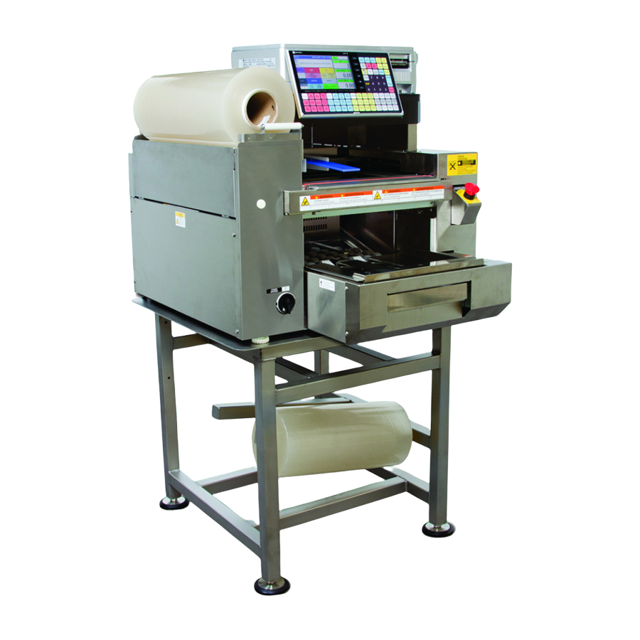
Chapter 1 Overview Chapter 1 Overview 1.1. Specifications 1.1.1 General Specifications Product Name WM-NANO Product Category Stretch Wrapper Product Lineup Single Film Wrapping Temperature: 5°C to 35 °C Environmental Conditions Humidity: 20 to 85% (no condensation) Dimensions M Type L Type... -
Page 8: Operation Unit Specifications
Chapter 1 Overview I t e m Ishida Wrap (Type M only): Content height of a tray must be up to 100 mm. Wrapping Tray Material PSP, PP Wrapping Tray Shape Rectangle (PSP, PP) Legged, soft, and/or atypical trays are not supported. -
Page 9: Reliability/Service Life
Conditions: Operating in 1000 packs/day, 350 days/year (4200 hours) 1.75 million packs for 5 years (21000 hours) Safety Complying to Ishida's product safety and warning indication standards, ETL, CE, C-Tick Standards Ishida's product standards and measurement laws of specified countries... -
Page 10: Part Names
Chapter 1 Overview 1.2. Part Names 1.2.1 Appearance... - Page 11 Chapter 1 Overview...
-
Page 12: Outline Dimensional Drawings
Chapter 1 Overview 1.3. Outline Dimensional Drawings 1.3.1 Dimensions Dimensions are shown below. Provide enough space for carry-in route, setup and maintenance. ●M type Film ●L type Film... -
Page 13: Installation Space
Chapter 1 Overview 1.4. Installation Space Provide enough working space for both sides of the machine. 1.5. Power Supply HEED THE FOLLOWING PRECAUTIONS ABOUT POWER SUPPLY: ● Use a power supply with rated voltage ground. Prepare a dedicated power source. ●... -
Page 14: Cautions For Unpacking
Chapter 1 Overview 1.6. Cautions for Unpacking <Before Unpacking> <After Unpacking> Do not use a lift under the product to carry. The product must be carried by hand. Insert hands to the holes red-circled in the picture below to lift and carry the product after unpacking. -
Page 15: Instruction For Carrying And Setting
Instruction for Carrying and Setting ・ The capacity for the stand of WM-NANO should be more than 200 kg(440 lb). Please make sure that customers’ stands or tables have same or more durability than the example written in this document before the setup. - Page 16 Chapter 1 Overview Right Back Back Lef t DO NOT HOLD When moving the machine by a trolley, please put it on a flat surface trolley. Note: Please make sure that the jack legs of the machine at the bottom side are on the trolley. Jack legs position Bottom side Jack legs...
-
Page 17: Setting On The Stand Or The Table
Setting on the Stand or the Table Note: The capacity for the stand of WM-NANO should be more than 200kg(440lb). Please make sure that customers’ stands or tables have same or more durability than the constitution example written below before the setup. -
Page 18: Setting On The Ishida Stand
Chapter 1 Overview 1.7.4 Setting on the Ishida Stand <Setting on the stand> Please be careful not to pinch your hands between the stand especially the pronging part of the top table (red-arrow parts) and the machine when you put the machine on. -
Page 19: Cabling Between Uni-7 And Wrapper
UNI-7. Slack off the communications cable and use with the clamp (with M3 TP screws, accessory of WM-NANO) to secure the cable on the plate. Communications cable Clamp (M3 TP screws) Countersunk... - Page 20 Chapter 1 Overview ●Communications Cable for Weighing Unit Attach the communications cable for the weighing unit to the side of UNI-7. Communications cable ●Adjusting Gap between UNI-7 and Wrapper Rotate UNI-7's adjusting feet to adjust the height so that the gap between UNI-7 and the wrapper unit should be about the diameter of the cable.
- Page 21 Chapter 1 Overview Setting a Film ■ Refer to the instruction manual for setting a film. This section describes important points for setting. ・ On the front end, set a film so that the end face of the film should be on the plane of the roller's end face.
-
Page 22: Chapter 2 Functions For Each Mode
Chapter 2 Functions for Each Mode This section describes additional functions available when connected to WM-NANO. For other functions, see UNI-7 service manual and instruction manual. Shown below are available functions: Mode Function Return Process at Power ON Normal Mode... -
Page 23: Normal Mode
Chapter 2 Functions for Each Mode Normal Mode 2.1.1 Return Process at Power ON A screen appears when the power is turned on that requires confirmation for the return process. 1. A screen appears when the power is turned on that requires confirmation for the return process of each drive unit. -
Page 24: 2.1.2 How To Use Preset Keys
Chapter 2 Functions for Each Mode 2.1.2 How to Use Preset Keys The following preset keys are available after connecting to WM-NANO. TRAY No. / WRAP ADJUST / CLEANING / HEATER ADJUST / WRAP STATUS / WRAP MODE / VOLUME / FILM REMOVE / FILM FEED / RETURN / ●TRAY No... - Page 25 Chapter 2 Functions for Each Mode The [WRAP ADJUST] screen appears. You can configure tray width, height, and depth. To change the setting, touch the [RETURN] button. VOLUME Indicates the height of the tray content. You cannot specify a value here. LENGTH(mm) Configures the tray width.
- Page 26 Chapter 2 Functions for Each Mode ●CLEANING Touching the [CLEANING] preset key moves up the lift and the left and right squeezing plates move toward the end for better cleaning. When you are ready for cleaning, touch the [START] button. ●HEATER ADJUST Touch the [HEATER ADJUST] preset key.
- Page 27 Chapter 2 Functions for Each Mode SEAL HEATER TEMPERATURE(°C): Configures the film sealing heater temperature. (Value range: 80 to 170℃) POWER: Switches on/off the film sealing heater power. FAN HEATER TEMPERATURE(°C): Configures the fan heater temperature. (Value range: 0 to 40°C) POWER: Switches on/off the fan heater power.
- Page 28 Chapter 2 Functions for Each Mode ●WRAP STATUS Touching the [WRAP STATUS] key displays the status of the wrapper. SEAL HEATER IS POWER OFF. The film sealing heater is off. EMRG. BTN IS PUSHED. The emergency stop button pressed. SEAL HEATER IS POWER ON(***) The film sealing heater is on.
- Page 29 Chapter 2 Functions for Each Mode ●FILM REMOVE Touching the [FILM REMOVE] preset key allows you to cut the film and remove it from the wrapper. ●FILM FEED Touching the [FILM FEED] preset key feeds the film. ●RETURN Touching the [RETURN] preset key performs return process of the drive units.
-
Page 30: Program Mode
Chapter 2 Functions for Each Mode PROGRAM Mode 2.2.1 WRAP Tab Added to PLU The WRAP tab has been added to PLU. In this screen, you can add [WRAP MODE], [TRAY No], and [VOLUME] to the product master. 1. Touch [PLU] in the PROGRAM mode screen. If [PLU] is not displayed, touch ▼... -
Page 31: Preset Keys Added
Chapter 2 Functions for Each Mode If no number is entered before touching the [TRAY No.] button, the tray list screen appears. 2.2.2 Preset Keys Added Shown below are added preset keys: TRAY No. / WRAP ADJUST / CLEANING / HEATER ADJUST / WRAP STATUS / WRAP MODE / VOLUME / FILM REMOVE / FILM FEED / RETURN For details of the added preset keys, see [] of the normal mode. -
Page 32: Tray Added To Menu
Chapter 2 Functions for Each Mode 3. The [FUNCTION] screen appears. The added preset keys are listed. You can select a preset key to assign. 2.2.3 TRAY Added to Menu 1. Touch [TRAY] in the PROGRAM mode screen. If [TRAY] is not displayed, touch ▼ or ▲ button until it appears. 2. - Page 33 Chapter 2 Functions for Each Mode 3. The [TRAY(BASIC)] screen appears. You can register basic tray information. VOLUME Indicates the height of the tray content. You cannot specify a value here. LENGTH Configures the tray width. HEIGHT Configures the tray height. WIDTH Configures the tray depth.
- Page 34 Chapter 2 Functions for Each Mode OTHER FILM LENGTH: Adjusts the film cut length. L/R FOLDERS: Adjusts the movement (squeezing amount) of the left and right squeezing plates. <> buttons: Squeeze outside, >< buttons: Squeeze inside 5. Touching the [ADJUST2] tab displays the [TRAY(ADJUST2)] screen. You can fine-adjust the tray information setting than in the [TRAY(ADJUST1)] screen.
- Page 35 Chapter 2 Functions for Each Mode L/R FOLDERS Adjusts the movement (squeezing amount) of the left and right squeezing plates. <> buttons: Squeeze outside, >< buttons: Squeeze inside For tray registration, enter the upper-end dimensions (wider/narrower side) "a" of the tray as shown in the figure below. The left and right squeezing plates operate based on the dimensions.
-
Page 36: Setup Mode
Chapter 2 Functions for Each Mode SETUP Mode 2.3.1 Switching to Service Mode To display all menu items of the SETUP mode, switch to the Service Mode. 1. In the SETUP mode screen, enter “495344" and touch the [PLU] key. The hidden menu appears. - Page 37 Chapter 2 Functions for Each Mode 2. The [KEY LOCK (DISPLAY KEY)] screen appears. Touch the [KEY LOCK(FUNCTION KEY)] tab. (The items in the red frames shown below have been added) Touch ▼ or ▲ button to display an item you want. 3.
-
Page 38: Items Added To Plu Overwrite
Chapter 2 Functions for Each Mode 2.3.3 Items Added to PLU OVERWRITE Items of TRAY No / WRAP MODE / VOLUME have been added to [PLU OVERWRITE]. 1. Touch [PLU OVERWRITE] in the SETUP mode screen. If [PLU OVERWRITE] is not displayed, touch ▼ or ▲ button until it appears. 2. -
Page 39: Wrap Tab Added To Plu Initial Data
Chapter 2 Functions for Each Mode 2.3.4 WRAP Tab Added to PLU INITIAL DATA The WRAP tab (TRAY No / WRAP MODE / VOLUME) has been added to [PLU INITIAL DATA]. 1. Touch [PLU INITIAL DATA] in the SETUP mode screen. If [PLU INITIAL DATA] is not displayed, touch ▼... -
Page 40: Items Added To Plu Update
Chapter 2 Functions for Each Mode If no number is entered before touching the [TRAY No.] button, the tray list screen appears. You can select a tray to configure. 2.3.5 Items Added to PLU UPDATE Items of TRAY No / WRAP MODE / VOLUME have been added to [PLU UPDATE]. 1. - Page 41 Chapter 2 Functions for Each Mode 3. Touch ▼ or ▲ button to display an item you want. The items in the red frames shown below have been added. 2-20...
-
Page 42: Country (Misc) Screen Added
Switches the temperature indication between °C (Celsius) and F TEMPERTURE (Fahrenheit). PLU’S WRAP PARAMETER RECEIVE: When the product master is sent from the host system, items related to the wrapper (*) are acquired. * Select this item if the host system supports WM-NANO. 2-21... -
Page 43: Tray Master Added To File Save / Load
SKIP: When the product master is sent from the host system, items related to the wrapper (*) are omitted. * Select this item if the host system does not support WM-NANO. (*) Items related to the wrapper = (TRAY No. / VOLUME / WRAP MODE) 2.3.7... - Page 44 Chapter 2 Functions for Each Mode 4. Select a tab to perform file input/output of a tray master. ● To input a tray master from a USB memory stick Select a tray master and touch [EXECUTE]. ● To output to a USB memory stick ①...
- Page 45 Chapter 2 Functions for Each Mode ● To initialize an internal tray master ① Touch the [SCALE INIT.] tab. ② Select a tray master and touch [EXECUTE]. 5. The confirmation screen appears. To execute, touch the [EXEC] button. 2-24...
-
Page 46: Adjust Mode
Chapter 2 Functions for Each Mode ADJUST Mode 2.4.1 Switching to Service Mode To display all menu items of the ADJUST mode, switch to the Service Mode. 1. In the ADJUST mode screen, enter "495344" and touch the [PLU] key. The hidden menu appears. -
Page 47: Sub Tab Added To Down Load
Chapter 2 Functions for Each Mode MASTER DATA CLEAR RESULT: Displays the execution result of the master data clear. CLEAR: Clears master data other than the device-specific information and configures minimum required data for operation. SYSTEM DATA INIT. RESULT: Displays the execution result of the system data initialization. CLEAR: Initializes the system data. - Page 48 Chapter 2 Functions for Each Mode PROGRAM FILE NAME Specifies a program. SEND MACHINE NAME Specifies a destination peripheral device for downloading. MAIN Specifies a program in the main unit's flash ROM as the source. Specifies a program in the USB memory as the source. EXECUTE Executes download.
-
Page 49: Wrapper Added To Menu
Chapter 2 Functions for Each Mode 2.4.4 WRAPPER Added to Menu The [WRAPPER] has been added to the ADJUST mode menu. You can configure the wrapper setting through this function. 1. Touch [WRAPPER] in the ADJUST mode screen. If [WRAPPER] is not displayed, touch ▼ or ▲ button until it appears. 2. - Page 50 Chapter 2 Functions for Each Mode ● To configure film ① Touch the [ADJUST1] tab. ② Specify setup value(s). FILM MATERIAL Touch < or > key to select a film material from: 1:PVC FILM 2:PS FILM1 3:PVC FILM2 * [1:PVC FILM] and [2:PS FILM1] have different setup temperatures of the sealing heater, while they are the same in the wrapping operation.
-
Page 51: Unit Test Added To Menu
Chapter 2 Functions for Each Mode FILM TEMPERATURE CHECK: Configures if the temperature in the wrapper should be checked before wrapping. FILM SENSOR CHECK: Specifies if the film existence should be detected for film feeding. DETECTION TIMEOUT: Specifies a time to determine that there is no film detected. -
Page 52: Wm-Nano Added To Model
WM-NANO Added to MODEL 1. Touch [MODEL] in the ADJUST mode screen. If [MODEL] is not displayed, touch ▼ or ▲ button until it appears. 2. The [MODEL] screen appears. Select a UNI-7 model and WM-NANO connection and type. 2-31... - Page 53 Chapter 2 Functions for Each Mode MODEL SELECT Select a UNI-7 model. WM-NANO Select whether WM-NANO is to be connected or not. WM-NANO TYPE Select a WM-NANO type. 3. After configuration, switching the screen displays the following screen. Turn off the power once and turn it on again.
-
Page 54: Chapter 3 Hardware (Mechanical)
Chapter 3 Hardware (Mechanical) Removing Units 3.1.1 Removing the Infeed Unit Infeed unit after being removed Infeed unit 1) Remove the weighing table. 2) Remove the garbage tray. Weighing table Garbage tray 3) Remove the screws (4) on both sides to remove the front cover. Upper screws: To be loosened Front cover... - Page 55 Chapter 3 Adjustment Mode 4) Remove the screws (4) that fix the front-right cover of the machine. * The screw position of the front-right cover may differ depending on specifications. In configuration shown below, remove the screw from the bottom. Remove the screw (1).
- Page 56 Chapter 3 Adjustment Mode 6) Remove screws (5) to remove the right lateral cover of the machine. Loosen the screws. Right lateral cover Loosen the screws Remove the on the front side. screw NOTE: In removing the right-side cover, pay attention not to deform the hinge of the cover.
- Page 57 Chapter 3 Adjustment Mode 8) Remove left- and right-side screws (3) that fix the infeed unit to the machine body. Screw in Screws in the back the back 9) Remove the infeed unit from the left- and right-side notches in the back. Left side Right side Notch...
- Page 58 Chapter 3 Adjustment Mode 11) Pull out the infeed unit from the machine body. 10) Remove the communication cable stored in the right lateral rail Rail Communicati on cable...
-
Page 59: Removing The Wrapping Unit
Chapter 3 Adjustment Mode 3.1.2 Removing the Wrapping Unit Wrapping unit Wrapping unit after being removed ■ Removing the cover 1) Remove the screws (4) that fix the front-right cover to remove the cover. * The screw position of the front-right cover may differ depending on specifications. - Page 60 Chapter 3 Adjustment Mode 2) Remove the front-right cover Remove the front-right cover. 3) Remove screws (5) to remove the right lateral cover. Loosen the screws. Right lateral cover Remove the screw Loosen screws on the front side. NOTE: In removing the right lateral cover, pay attention not to deform the hinge of the cover...
- Page 61 Chapter 3 Adjustment Mode 4) Remove screws (3) to remove the front-left cover. Front-left cover Remove Loosen the screws screw (1). (2). * The screw position of the front-left cover may differ depending on specifications. In the configuration shown below, remove the screw from the bottom.
- Page 62 Chapter 3 Adjustment Mode 4) Remove screws (4) to remove the left lateral cover. Loosen the screws. Loosen the screws on the front side. Left lateral cover NOTE: In removing the left lateral cover, pay attention not to deform the hinge of the cover. 5)...
- Page 63 Chapter 3 Adjustment Mode 6) Remove screws (3) to remove the back-left cover. Back left cover Loosen the screws on the left lateral. 7) Remove screws (2) to remove the back-right cover. Back right cover 9) Loosen the screws (2) on the right side of the 8)...
- Page 64 Chapter 3 Adjustment Mode 10) Remove the cover by turning it from the bottom. 3-11...
- Page 65 Chapter 3 Adjustment Mode ■ Removing the operation unit 1) Remove the screws (2) to remove the power 2) Pull out the power cable. cable retaining bracket on the left lateral of the machine. Retaining bracket Power cable 3) Pull out the communication cable at the 4)...
- Page 66 Chapter 3 Adjustment Mode ■ Removing the Wrapping Unit 1) Remove the wire harness that connects the wrapping unit to the underneath machine body unit. First, pull out the wire harness stored in the front left side and disconnect the connectors (3 sets). Pull out the wire harness.
- Page 67 Chapter 3 Adjustment Mode 4) Check that the wrapping unit has slided properly. The wrapping unit has slided properly to the removable position if the notches on the front and back are released. Front Before sliding After sliding The notch is locked. The notch is released.
- Page 68 Chapter 3 Adjustment Mode 5) Lift and remove the wrapping unit. When carrying the unit, hold the outside frame Do not hold the film arm portion on the left portions. lateral. 6) Rest the wrapping unit against some object or place it horizontally. <Resting the unit against some object>...
-
Page 69: Dividing The Film Conveying Unit Into Two
Chapter 3 Adjustment Mode 3.1.3 Dividing the Film Conveying Unit into Two ■ Removing the Film Conveying Unit Procedure after removing the wrapping unit from the machine body is described below. For procedures to disassemble the squeezing unit, refer to “Removing the Wrapping Unit.” Film conveying unit Film conveying unit after being removed... - Page 70 Chapter 3 Adjustment Mode 2) Remove the guide rails on the left and right sides. Right-side guide rail: Loosen the screws (2) on the front and back sides. Guide rail Front side Back side 3-17...
- Page 71 Chapter 3 Adjustment Mode Left-side guide rail: Loosen the screws (2) on the front and back sides. Guide rail Front side Back side 3) Remove the belt at the left side back from the roller. Left lateral 3-18...
- Page 72 Chapter 3 Adjustment Mode 4) Remove screws (4) to remove the cutter blade. We recommend that the cutter blade be removed for safety. It might cause physical injury on removing the film conveying unit. Cutter blade 5) Remove the screws (4) at the four corners that fix the film conveying unit.
- Page 73 Chapter 3 Adjustment Mode 6) Remove the film conveying unit directly upward. Solenoid and clamp fittings (Left side: 2 locations, Right side: 2 locations) Film detection sensors (2 locations) Right lateral NOTE: NOTE: In removing the film conveying unit, pay attention In removing the film conveying unit, lift the unit not to hit the film detection sensors (at 2 locations).
- Page 74 Chapter 3 Adjustment Mode Dividing the Film Conveying Unit into Two ■ 1) Remove the screws (4) at the four corners. 2) Lift the upper portion of the film conveying unit. 3-21...
- Page 75 Chapter 3 Adjustment Mode ■ Replacing the round belts ●Mounting positions for roller round belts < M type> Upper roller Lower roller < L type> Upper roller Lower roller 3-22...
- Page 76 Chapter 3 Adjustment Mode ●Procedure to replace round belts Length of round belts comes in two types: Long and short. Different replacement procedure is required for different length. ・For long round belts Remove the round belts from the roller for replacement. ・For short round belts 1)...
- Page 77 Chapter 3 Adjustment Mode 5) Remove screws (2) to remove one side of the roller of the short round belts. Roller Screws (2) 6) Replace the short round belts. ● Assembly after replacing the short belts Assembly procedure follows in the reverse direction of the procedure for dividing the unit into two. If assembly is conducted with the unit lying flat, the film conveying unit may be deformed into a parallelogram shape.
- Page 78 Chapter 3 Adjustment Mode 3) Adjust the upper and lower film conveying units 4) Firmly tighten the rail screws (2) that have been to the proper position. temporarily tightened with the unit held in the standing position. Screws (2), to be firmly tightened 5)...
- Page 79 Chapter 3 Adjustment Mode ■ Mounting the Film Conveying Unit 1) Place the film conveying unit directly from the above. Solenoid and clamp fittings (Left side: 2 locations, Right side: 2 locations) Insert into the hole. Film detection sensors (2 locations) Right lateral NOTE:...
- Page 80 Chapter 3 Adjustment Mode 4) Tighten screws (4) to mount the left- and right-side guide rails. In mounting the guide rails, identify their directions (left or right) as follows: Left side: Having a notch Right side: Having a screw hole to fix the emergency stop switch Guide rail Guide rail Notch...
-
Page 81: Points For Unit Assembly
Chapter 3 Adjustment Mode 3.1.4 Points for Unit Assembly Carry out assembly basically in the reverse direction of disassembly. Only main points are described below. In mounting the wrapping unit: Coupling arms In placing the wrapping unit on the machine body, couple the postsqueezing arm and pusher arm up and down. -
Page 82: Adjustment
Chapter 3 Adjustment Mode Adjustment 3.2.1 Adjusting Clamp Position ■ Clamp plate mounting position When the clamp plate of the film conveying unit is removed or replaced, the clamp plate must be fixed in a proper position. Center clamp plate Left and right clamp plates Left and right clamp... - Page 83 Chapter 3 Adjustment Mode In the case shown in the photograph below, mount the clamp plates at a lifted position shown in the direction of arrows as much as possible. Fix each clamp plate with screws (2). Fix the left and right clamp plates at the back with screws (2). Left right Center...
- Page 84 Chapter 3 Adjustment Mode ■ Checking the clamp Check whether the clamp can catch film. Test run and check the clamp by using a piece of paper. Prepare a long and thin piece of paper. 1) Touch the [Unit Operation] in the Maintenance 2)...
- Page 85 Chapter 3 Adjustment Mode Adjusting clamp solenoid Adjust the solenoids that open and close the clamps. Four solenoids are used to open and close the front and back clamps. Screw holes are elongated so that position is adjusted with screws (2 screws for each solenoid). Solenoids are associated with each clamp as shown below.
-
Page 86: Adjusting Lift Height
Chapter 3 Adjustment Mode 3.2.2 Adjusting Lift Height Adjust the lift height with 4 mm hexagonal nuts. Prepare two 4 mm hexagonal nuts 1) Remove the screws (2) on top side of the cover. 2) Release the lock lever to remove the lift head. Another cover in the back of the cover comes off. - Page 87 Chapter 3 Adjustment Mode 6) Lower the lift to the lowest position resting on the hexagonal nut. (Conduct adjustment in this position.) 7) Loosen hexagonal bolts on both sides (2 on the left and 2 on the right) to adjust height. Hexagonal bolts 8)...
- Page 88 Chapter 3 Adjustment Mode 10) If the gap is not 1 – 3 mm, repeat the above procedure 5 through 9 to adjust height. If the gap still does not fall in the range of 1 – 3 mm, loosen the hexagonal bolts (3) in the back to adjust height in a similar way.
-
Page 89: Adjusting The Film Arm
Chapter 3 Adjustment Mode 3.2.3 Adjusting the Film Arm Film arm adjustment includes the following items. •Operating range adjustment for the film arm in the lateral direction (inside - outside) (adjusted with screws) •Roller position adjustment for the film arm (adjusted with nuts) •Film holder position adjustment (adjusted with screws) Operating range... - Page 90 Chapter 3 Adjustment Mode [1] Checking the film arm position Check that the film arm is in the proper position before adjusting the film arm. •Check that the film holder is parallel with the roller. Check the parallelism from the near side to the back side. Film arm roller Film arm holder Back side...
- Page 91 Chapter 3 Adjustment Mode 2) Move the entire film arm to adjust the position so that the belt runs on the concave portion. 3) Check that the film arm roller is parallel with the conveying unit roller. Conveying unit roller Film arm roller 3-38...
- Page 92 Chapter 3 Adjustment Mode [2] Adjusting inside stopper position Set the operating range of the film arm in the lateral direction. Set the inside limit position as follows: 1) Loosen the screw of the inside stopper (near 2) Push the film arm until the tip of the film arm side).
- Page 93 Chapter 3 Adjustment Mode [3] Adjusting film arm roller position 1) Set the film arm roller position at the top. Loosen the outside nut and fix it at the uppermost position of the elongate hole (the roller is at the top position). Film arm Fix the nut at the top position...
- Page 94 Chapter 3 Adjustment Mode [4] Adjusting film holder position 1) Lower the film holder (set it at the origin position). Adjust the position in this condition and fix the holder with screws (2). Lift the film holder until the roller and the hook and loop fastener hit each other lightly and fix the holder with screws (2).
- Page 95 Chapter 3 Adjustment Mode •Adjustment is OK if the roller revolves smoothly with the film arm pushed into the farthest back (until it hits the stopper). Film arm Roller [5] Adjusting outside stopper position 1) Lift the cutter and adjust the outside stopper’s 2)...
- Page 96 Chapter 3 Adjustment Mode [6] Adjusting solenoid 1) Adjust each solenoid’s position as follows. Release Drive solenoid solenoid Screw hole is elongated.. Adjust the screw Release Drive solenoid position so that the iron core is most inside the solenoid solenoid, and then, fix the screw. Drive solenoid: It shifts the film arm toward inside (film conveying position).
- Page 97 Chapter 3 Adjustment Mode [7] Adjusting the detection plate of the film conveyance origin point sensor (cutter safety sensor). Before this adjustment, carry out “(4) Adjusting outside stopper position” to adjust the gap between the the film arm and the cutter blade to 4 – 5 mm. 1)...
- Page 98 Chapter 3 Adjustment Mode 5) If reaction does not occur at around the middle 6) Repeat the procedure 3 – 5 until the sensor point, adjust the position of the detector plate. reacts at around the middle point. The screws (2) fixing the detection plate have elongated holes.
-
Page 99: Adjusting The Mini-Keeper
Chapter 3 Adjustment Mode 3.2.4 Adjusting the Mini-keeper Mini-keeper adjusts revolving conditions of the film conveyer by applying load to the roller. Set the mini-keeper to the position tightened by one revolution from the most loosened condition. 1) Pull the stopper and revolve the mini-keeper in 2)... -
Page 100: Adjusting The Operating Range Of The Infeed Unit's Claw
Chapter 3 Adjustment Mode 3.2.5 Adjusting the Operating Range of the Infeed Unit’s Claw Adjust the claw operating range so that the gap between the infeed bar and the weighing plate is 10 mm when the infeed bar is at the farthest position in the back (farther back than the standby position). M type: 10 mm, L type: 5 mm 1)... - Page 101 Chapter 3 Adjustment Mode 4) If the dimension is not 10 mm, stop unit’s operation and adjust the operation range of the infeed unit’s claw. Carry out two types of adjustment for the claw operation range as described below.. •Adjustment of the position where the claw stops (no change in stroke width) •Adjustment of claw’s stroke width •Adjustment of claw’s stroke width Adjust position of screws (2).
-
Page 102: Adjusting Cutter Solenoid Position
Chapter 3 Adjustment Mode 3.2.6 Adjusting Cutter Solenoid Position Fix the cutter solenoid with screws (2) at the position where the iron core is the most inside of the solenoid. 1) Turn the machine power switch OFF. 2) Loosen the screws (2) that fix the cutter solenoid. Screw 3)... -
Page 103: Adjusting Cutter Blade Position
Chapter 3 Adjustment Mode 3.2.7 Adjusting Cutter Blade Position Adjust the cutter blade position when cutter blades are replaced or the unit is disassembled. Screw holes are elongated allowing vertical adjustment. Fix the cutter blade position with screws (4). Adjust the cutter blade position in a manner described below. •If the cutter bracket has a mark-off line, adjust the cutter blade to the mark-off line. -
Page 104: Adjusting Left And Right Squeezing Plates Widening Amount
Chapter 3 Adjustment Mode 3.2.8 Adjusting Left and Right Squeezing Plates Widening Amount Adjust the widening amount between the left and right squeezing plates to 366 – 369 mm. 1) Touch the [UNIT TEST] in the Adjustment 2) Select [LEFT/RIGHT FOLDERS] and touch Mode. -
Page 105: Adjusting Squeeze Amount Of The Postsqueezing Plate
Chapter 3 Adjustment Mode 3.2.9 Adjusting Squeeze Amount of the Postsqueezing Plate Adjust the squeeze amount of the postsqueezing plate in such a way that the gap created by the postsqueezing plate when the postsqueezing plate moves toward the nearest position is within 5 mm ± 1 1)... -
Page 106: 3.2.10 Adjusting Discharge Pusher Standby Position
Chapter 3 Adjustment Mode 3.2.10 Adjusting Discharge Pusher Standby Position Adjust the standby position of the discharge pusher as follows: 1) Check that the standby position of the discharge pusher (from the front of the discharge pusher to the backside of the plate) is 261 - 264 mm. Front of the discharge pusher Distance to the standby position:... -
Page 107: 3.2.11 Adjusting Tray Holder Height
Chapter 3 Adjustment Mode 3.2.11 Adjusting Tray Holder Height Adjust the height of the tray holder as follows: Adjust the space between the front end of the tray holder and the plate to 20±1 mm with a hexagonal bolt. Tray holder front end (top end) Hexagonal bolt 20±1 mm... -
Page 108: 3.2.12 Adjusting Claw Height Of The Infeed Unit
Chapter 3 Adjustment Mode 3.2.12 Adjusting Claw Height of the Infeed Unit Adjust the claw height of the infeed unit as follows: 1) Loosen the screws (4) on the right lateral of the infeed unit. 2) Adjust the space between the top surface of the infeed unit and the infeed bar to 6 - 7 mm. Measure the height at the back of the front claw on the right lateral of the infeed unit as shown in the photograph below. -
Page 109: Chapter 4 Hardware (Electrical)
Chapter 4 Hardware (Electrical) Chapter 4 Hardware (Electrical) Electrical Unit Board Configuration When a worker put his/her hand inside the machine body, be sure to press the emergency stop switch. Pay full attention that the DC 24V power source for the logic system does not turn off even though the emergency stop button is pressed. -
Page 110: Front Weighing Unit
Chapter 4 Hardware (Electrical) 4.1.2 Front Weighing Unit Main power switch P-930* – Dip switch setting Emergency stop switch Board Name / Function Parts Name Main power switch Main power switch of the machine Emergency stop Pressing the switch activates the electromagnetic contactor and switch shuts off the power source for the drive system. -
Page 111: Wrapping Control Unit (1/2)
Chapter 4 Hardware (Electrical) 4.1.3 Wrapping Control Unit (1/2) Circuit breaker Fuse Board Name / Function Parts Name E1 DC Brushless motor For the main cam motor driver board (BLHD100K-K12) K1 Electromagnetic It controls the 24V system power supply by ON/OFF operation of contactor the emergency stop switch for DC 24V. -
Page 112: Wrapping Control Unit (2/2)
Chapter 4 Hardware (Electrical) 4.1.4 Wrapping Control Unit (2/2) P-1004* Dip switch setting P-1006*-4 NOTE: Be sure to set SW2 to ON. If SW2 is set to OFF, program cannot be downloaded. Board Name / Function Parts Name Wrapping control It implements wrapping machine control. -
Page 113: Chapter 5 Troubleshooting
Chapter 5 Troubleshooting Chapter 5 Troubleshooting Operation as IP (Scale and Printer) This section describes the procedure to use the wrapper as an IP (scale or printer only) in case that the wrapper is disabled due to a trouble, etc. 1 Turn OFF the power of the wrapper unit. -
Page 114: Error Messages
Chapter 5 Troubleshooting Error Messages 5.2.1 Error Display When the machine detects an error, the error message and error number shown below are displayed. Depending on the error type, the machine may be recovered by performing only button operations, simple procedure and button operations, or maintenance such as parts replacement. -
Page 115: Error List
Chapter 5 Troubleshooting Error List 5.3.1 Error relates to System (Code 100s) ID NO. TITLE ERROR CONTENTS SOLUTION 0101 SYSTEM ERROR System became unstable. REBOOT It could not implement the dynamic allocation (malloc) in the memory. (The memory for program to work became full.) leaking of the memory 0102... - Page 116 Chapter 5 Troubleshooting ID NO. TITLE ERROR CONTENTS SOLUTION 0107 CLOCK SETTING IS The setting of the clock is not [OK] NOT COMPLETED completed. The setting of the clock is necessary. After the board is replaced, the setting of the clock has not been implemented yet.
-
Page 117: Error Relates To Memory (Code 200S)
Database was being abnormal, and [OK] it could not be recovered even from the backup. 0192 WM-NANO TYPE The model of WM-NANO type (M [OK] IS DIFFERENT type/L type) is different. In case SUBERROR is 0000/0002, <SUBERROR No.> setup the machine to L type. - Page 118 Chapter 5 Troubleshooting ID NO. TITLE ERROR CONTENTS SOLUTION 0213 FREE MSG. 2 Free Message 2 that was called up [SET] Only releasing the error MASTER ISN’T is not programmed in the Free message. PROGRAMMED Message 2 master. [DELETE] Deletes the Free Called Free Message 2 No.
- Page 119 Chapter 5 Troubleshooting ID NO. TITLE ERROR CONTENTS SOLUTION [OK] 0229 FILE SYSTEM IS File system has some problems. It is necessary to do Memory ABNORMAL Access to the database failed. Initialization. [OK] 0266 FILE INPUT ERROR It failed to input the file. It failed to input the data at the file input/output operation.
- Page 120 Chapter 5 Troubleshooting ID NO. TITLE ERROR CONTENTS SOLUTION [OK] 0282 TARE WEIGHT IS Error that tare value was not programmed. (Except for USA) Tare value is not programmed. [OK] 0283 TARE LIMIT OVER Tare value was beyond the limit. (MAX 9.990lb) (USA) Programmed tare (total tare) went...
- Page 121 Chapter 5 Troubleshooting ID NO. TITLE ERROR CONTENTS SOLUTION [SET] Only releasing the error 0293 FREE MSG.13 Free Message 13 that was called up MASTER ISN’T is not programmed in the Free message. PROGRAMMED Message 13 master. [DELETE] Deletes the Free Called Free Message 13 No.
-
Page 122: Error Relates To Checking (Code 300S)
Chapter 5 Troubleshooting 5.3.3 Error relates to checking (Code 300s) ID NO. TITLE ERROR CONTENTS SOLUTION 0301 EMERGENCY [OK] and release Emergency switch Emergency switch is pressed when SWITCH HAS the machine started moving. BEEN PUSHED 0306 RIGHT SIDE Right side cover is open when the [OK] and close the right side cover COVER IS OPEN machine started moving. - Page 123 Chapter 5 Troubleshooting ID NO. TITLE ERROR CONTENTS SOLUTION 0321 PRICE IS NOT [OK] Price is not programmed. PROGRAMMED <SUB ERROR No.> 0: No Price 1: No Weight 2: No Unit Price 3: When campaign is [9:S.P. ARB.], the quantity is not matching the programmed quantity in campaign setting.
- Page 124 Chapter 5 Troubleshooting ID NO. TITLE ERROR CONTENTS SOLUTION 0341 PRODUCT IS The product is remaining on the lift. [OK] REMAINING ON The operation that was prohibited Discharge the item inside by pressing THE LIFT during the production was PLU key, and then start the operation. implemented when there was an item in produce around the scale to the lift.
- Page 125 Chapter 5 Troubleshooting ID NO. TITLE ERROR CONTENTS SOLUTION 0350 TRAY No. IS NOT Tray No. is not programmed to the [OK] PROGRAMMED product. When you operate [WRAP] or [WRAP + PRINT], selecting the tray is necessary. When you operate only [PRINT], change the [WRAP MODE] to [PRINT].
-
Page 126: Printers (No. 700S To 900S, 1600S, And 1800S)
Chapter 5 Troubleshooting ID NO. TITLE ERROR CONTENTS SOLUTION 0393 TRACEABILITY It has changed the Lot No. that was [EXEC]: Validate the change. programmed on the memory. [STOP]: Invalidate the change. It changed the Lot No. that has been used before (=that is programmed on the memory). - Page 127 Chapter 5 Troubleshooting ID NO. TITLE ERROR CONTENTS SOLUTION 0405 FIFO FOR FIFO for wrapper is full. REBOOT WRAPPER IS FULL The wrapper software is managing the wrapping movement by putting the sequence numbers on each product. But, at this time, the declination of management of sequence number occurred, and the machine could not continue...
- Page 128 Chapter 5 Troubleshooting ID NO. TITLE ERROR CONTENTS SOLUTION 0415 REAR FOLDER IS Rear folder is not at the original [RETURN] NOT ORIGINAL position. (SUB ERROR No.:0010) <Check Point> POSITION When the rear folder starts moving, 1. Check the rear folder operation the rear folder home position sensor completion verification sensor did not detect the rear folder.
- Page 129 Chapter 5 Troubleshooting ID NO. TITLE ERROR CONTENTS SOLUTION 0416 MOTOR FOR L/R Error for the motor of L/R folders [RETURN] FOLDERS IS <Check Point> The motor for L/R folders did not ABNORMAL 1. L/R folders motor driver P-1006 [A2] move properly.
- Page 130 Chapter 5 Troubleshooting ID NO. TITLE ERROR CONTENTS SOLUTION 0418 FEEDER MOTOR Error for the film feeder motor [RETURN] IS ABNORMAL <Check Point> The motor for film feeder did not 1. Film feed motor driver P-1006 [A2] move properly. 2. Film feed motor [M2] <SUB ERROR No.>...
- Page 131 Chapter 5 Troubleshooting ID NO. TITLE ERROR CONTENTS SOLUTION 0449 DON’T PUT YOUR The safety sensor at the out-feed After checking there is no products or HANDS INTO THE part was cut during the operation. some objects inside, press [RETURN]. MACHINE This appears when the safety sensor is cut (by hands or products)
- Page 132 Chapter 5 Troubleshooting ID NO. TITLE ERROR CONTENTS SOLUTION 0471 THERE IS There is a problem at the wrapper Reboot the machine PROBLEM ON controller unit. WRAPPING The controller board of wrapper has CONTROLLER a problem. <SUB ERROR> 0002: External RAM problem 0003: E2ROM writing problem 0088: Communication IC problem 0999: Overdrive.
- Page 133 Chapter 5 Troubleshooting ID NO. TITLE ERROR CONTENTS SOLUTION 0480 FILM IS [RETURN] Film is remaining. REMAINING 1. It started wrapping or feeding the film with the film remaining inside of the wrapper. Remove the film inside. 2. It misunderstood that the film is remaining either because film-detecting sensor is broken, or some dirt is on the sensor.
- Page 134 Chapter 5 Troubleshooting ID NO. TITLE ERROR CONTENTS SOLUTION 0482 FAILED TO FEED [RETURN] It failed to feed the film. FILM - When sub-error No. is 100 –102, it is 1. When the cutter tries to move, the necessary to open the left side cover film set arm is not back to the home to release the error.
- Page 135 Chapter 5 Troubleshooting ID NO. TITLE ERROR CONTENTS SOLUTION 0485 AUXILIARY FOR A sub connecting problem of electro [RETURN] MAGNETIC magnetic unit This error tends to happen when the CONTACT IS cover is not closed completely. Contradiction between “status for ABNORMAL <Check Point>...
- Page 136 Chapter 5 Troubleshooting ID NO. TITLE ERROR CONTENTS SOLUTION 0494 PROBLEM ON A problem happened at wrapper [OK] WRAPPING PART side. Download the wrapper application. The wrapper software is not - Wrapper application 1 when downloaded. Or the wrapper sub-error is 0000. software cannot be recognized.
-
Page 137: Error Relates To Wrapper (Code 500S)
Chapter 5 Troubleshooting ID NO. TITLE ERROR CONTENTS SOLUTION 0498 PROBLEM ON System error for wrapper. Reboot. WRAPPING PART A bug happened at wrapper program. 5.3.5 Error relates to wrapper (Code 500s) ID NO. TITLE ERROR CONTENTS SOLUTION 0524 FAILED TO Failed to discharge item. - Page 138 Chapter 5 Troubleshooting ID NO. TITLE ERROR CONTENTS SOLUTION 0701 CANNOT Cannot communicate with printer [REEXEC] button Re-check the COMMUNICATE Printer is not connected. communication with printer WITH PRINTER 1 Error has happened at the [STOP] button Release the error communication with printer.
- Page 139 Chapter 5 Troubleshooting ID NO. TITLE ERROR CONTENTS SOLUTION 0714 REMAINING LABEL Label is remaining. [OK] ON PRINTER 1 -Printer tried to move even when -Remove the label -Adjust the peel sensor a label is remaining on the printer -Adjustment of peel sensor is not correct and it misunderstands the label is remaining at the printer.
-
Page 140: Error Related To Scale (Code 1600S)
Chapter 5 Troubleshooting ID NO. TITLE ERROR CONTENTS SOLUTION 0725 No second label Cannot print the second label. [OK] printing The 2 nd label format No. is not being [36 (Nutrition Format)] when it set [YES] at Nutrition printing with preset key [NIP Y/N]. - Page 141 Chapter 5 Troubleshooting ID NO. TITLE ERROR CONTENTS SOLUTION 1625 TAKE ITEM OFF Remove the item from the scale [OK] THE PLATTER platter. Please remove the item from the scale platter. It appears when the tray or wrapping mode is changed while there is something on the scale (or when the scale is not at [ZERO] point) with the tare...
-
Page 142: Appendix 1 Periodic Replacement Parts
Appendix 1 Periodic Replacement Parts Appendix 1 Periodic Replacement Parts ■ Parts needing periodic replacement 1: Periodic replacement parts (Replacement cycle differs depending on usage status.) Parts Name Remarks Expected Damage Replacement Cycle (Common Name) (approximate) Deterioration of gripping Printing roller Printer 2 years and 6 months force due to wear... -
Page 143: Appendix 2 Wrapping By Wm-Nano
Appendix 2 Wrapping by WM-NANO Appendix 2 Wrapping by WM-NANO 2.1 Part Names Names of each part are given in Figures1 and 2. Rear squeezing plate Eject pusher Left and right Left and right squeezing plate squeezing plate Machine body... -
Page 144: 2.2 Wrapping Operation
Appendix 2 Wrapping by WM-NANO 2.2 Wrapping Operation 1) Basic steps of wrapping operation After the scale has stabilized, start film conveying and tray feeding. After completing film conveying, start lift elevation. After completing film elevation, left and right squeezing plates squeeze in (Figure4). - Page 145 Appendix 2 Wrapping by WM-NANO Figure 5 Lift starts descending. Figure 6 Left and right squeezing plates and rear squeezing plate finish squeezing. Appendix 2-3...
- Page 146 Film material selection: Possible range of wrapping is almost the same for “Poly 1.” <M type> Ishida Wrap/Ishida Wrap Super: Film width 350 mm ● Trays with good wrapping condition Trays impossible for wrapping :Verified for wrapping feasibility by tests...
- Page 147 Appendix 2 Wrapping by WM-NANO M type> < Ishida Wrap/Ishida Wrap Super: Film width 400mm ● Trays with good wrapping condition Trays impossible for wrapping :Verified for wrapping feasibility by tests Long side of the tray[mm] ● ● ● ●...
- Page 148 Appendix 2 Wrapping by WM-NANO type> <L MAP-M: 400 mm in width ● Trays with good wrapping condition Trays impossible for wrapping :Verified for wrapping feasibility by tests Long side of the tray[mm] ● ● Figure 10 Appendix 2-6...
- Page 149 Appendix 2 Wrapping by WM-NANO type> <L MAP-M: 500 mm in width ● Trays with good wrapping condition Trays impossible for wrapping :Verified for wrapping feasibility by tests Long side of the tray[mm] ● ● ● ● Figure 11 Appendix 2-7...
- Page 150 Appendix 2 Wrapping by WM-NANO type> <L MAP-M: 560 mm in width ● Trays with good wrapping condition Trays impossible for wrapping :Verified for wrapping feasibility by tests Long side of the tray[mm] ▲ ● ● ● ● ● ●...
- Page 151 Appendix 3 Electric Wiring Diagram Page 1 200 - 240 VAC X307 Temperature fuse (158°C) Fan heater 277W/400W YL2R YL2P 8-84 Power supply switch FUSE FUSE HOLDER F7-1 V2-M3 F7-2 V1.25-M3 250V 5A F1 F2 F3 F4 AQJ116V F-65AD カバーツキ Fan heater SSR 250# 250V 6A...
- Page 152 MATERIAL FINISH SCALE EHP-5 記号・箇所 日付 設変 担当者 尺度 △ Cover unit TxVcc TxGND 10-2 △ 図名 Harness unit (10) DESIGNED DRAWN TITLE 設計 製図 ハイセンズ’WM-NANO’2 △ 120703 △ 海外/国内仕様 図番 APPROVED CHECKED DWG.No. 承認 検図 138-2307-00 ...
- Page 153 Appendix 3 Electric Wiring Diagram Page 3 X307 200 - 240 VAC Temperature fuse (158°C) Fan heater 277W/400W YL2R YL2P 8-84 FUSE FUSE HOLDER F7-1 V2-M3 F7-2 V1.25-M3 250V 5A Power supply switch F1 F2 F3 F4 AQJ116V F-65AD with cover 250# Fan heater SSR 250V 6A...
Need help?
Do you have a question about the WM-NANO and is the answer not in the manual?
Questions and answers