Sign In
Upload
Download
Table of Contents
Contents
Add to my manuals
Delete from my manuals
Share
URL of this page:
HTML Link:
Bookmark this page
Add
Manual will be automatically added to "My Manuals"
Print this page
×
Bookmark added
×
Added to my manuals
Manuals
Brands
LG Manuals
Stereo System
FAS166F
Service manual
LG FAS166F Service Manual
Hide thumbs
Also See for FAS166F
:
Owner's manual
(26 pages)
1
2
3
4
5
6
7
8
9
10
11
12
13
14
15
16
17
18
19
20
21
22
23
24
25
26
27
28
29
30
31
32
33
34
35
36
37
38
39
40
41
42
43
44
45
46
47
48
49
50
51
52
53
54
55
56
57
58
59
60
61
62
63
64
65
page
of
65
Go
/
65
Contents
Table of Contents
Troubleshooting
Bookmarks
Table of Contents
Section 1 Summary
Table of Contents
Servicing Precautions
Esd Precautions
Service Information for Eeprom
Program Download Guide
Specifications
Section 2 Cabinet & Main Chassis
Exploded Views
Cabinet and Main Frame Section (Fa166)
Deck Mechanism Section (Scp-03B)
Packing Accessory Section
Speaker Section (Fas166F)
Section 3 Electrical
Training Master
No Sound from Speakers
No Sound in Port. in Function
No Sound in Ipod Function
No Sound in Am/Fm Function
No Sound in CD Function
No Sound in Usb Function
No Power
One Point Repair Guide
No Power Problem
Speaker no Audio Output
Usb no Detect
No Booting
Electrical Troubleshooting Guide
Power (Smps)
P-Sens
Vkk Check
Μ-COM PART CHECK-1
Μ-COM PART CHECK-2
Fld Display Check
Touch Part Check
Pwm Modulation Check
Power Amp Part Check
Tuner Function Check
Usb Function Check
CD Function Check
Waveforms
Servo
Motor Drive
Audio Path
Adc
Ipod
Usb
Crystal
Wiring Diagram
Block Diagrams
Main Block Diagram
Smps Block Diagram
Circuit Diagrams
Smps Circuit Diagram
Main-Micom Circuit Diagram
Main-Adc/Ipod Circuit Diagram
Main-Mpeg(Dsp) Circuit Diagram
Main-Rf Servo Circuit Diagram
Main-Power Circuit Diagram
Amp Circuit Diagram
Front Circuit Diagram
Front Jack Circuit Diagram
Ipod Docking Circuit Diagram
Circuit Voltage Chart
Printed Circuit Board Diagrams
Main P.C.board
Smps P.C.board
Amp P.C.board
Front P.C.board
Front Jack P.C.board
Ipod Docking P.C.board
Advertisement
Quick Links
1
Specifications
2
Cabinet and Main Frame Section (Fa166)
3
Speaker Section (Fas166F)
4
No Sound in CD Function
5
CD Function Check
Download this manual
See also:
Owner's Manual
Internal Use Only
Website http://biz.lgservice.com
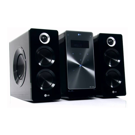
Micro Hi-Fi System
SERVICE MANUAL
MODEL: FA166
(FA166, FAS166F)
CAUTION
BEFORE SERVICING THE UNIT, READ THE "SAFETY PRECAUTIONS"
IN THIS MANUAL.
P/NO : AFN74972260
MARCH, 2011
Table of
Contents
Previous
Page
Next
Page
1
2
3
4
5
Advertisement
Chapters
Section 1 Summary
3
Section 2 Cabinet & Main Chassis
12
Section 3 Electrical
18
Table of Contents
Need help?
Do you have a question about the FAS166F and is the answer not in the manual?
Ask a question
Questions and answers
Related Manuals for LG FAS166F
Stereo System LG FA166DAB Owner's Manual
Micro hi-fi system (26 pages)
Stereo System LG FA163-A0U Quick Start Manual
(12 pages)
Stereo System LG FA163-A0P Quick Start Manual
(12 pages)
Stereo System LG FA163DAB Manual
Lg 160w idock micro audio system (16 pages)
Stereo System LG FA163 Quick Manual
(12 pages)
Stereo System LG FA162 Owner's Manual
Micro hi-fi system (16 pages)
Stereo System LG FA-162 Owner's Manual
(16 pages)
Stereo System LG FA164DAB Manual
Dab micro system (14 pages)
Stereo System LG FA164 Owner's Manual
Micro hi-fi system (fa164-d0p, fas164f) (14 pages)
Stereo System LG FA164 Series Owner's Manual
(24 pages)
Stereo System LG FA164U Owner's Manual
(12 pages)
Stereo System LG FAS164F Owner's Manual
(14 pages)
Stereo System LG FA64 Manual
(92 pages)
Stereo System LG FA64 Manual
(11 pages)
Stereo System LG FAS64 Manual
(10 pages)
Stereo System LG FA64-A0U Quick Start Manual
(11 pages)
This manual is also suitable for:
Fa166
Table of Contents
Print
Rename the bookmark
Delete bookmark?
Delete from my manuals?
Login
Sign In
OR
Sign in with Facebook
Sign in with Google
Upload manual
Upload from disk
Upload from URL


Need help?
Do you have a question about the FAS166F and is the answer not in the manual?
Questions and answers