Table of Contents
Advertisement
Instructions for customer
service engineers
Automatic gas firing device BIC 960
TopTronic
®
T / TopTronic
UltraGas
(15-1000)
®
CompactGas
(200-280)
®
Modifications to the automatic gas firing device should
only be performed by authorised persons. This manual
is therefore intended for use by qualified engineers.
Subject to modifi cations
®
E
|
4 205 503 / 14 - 10/15
These instructions apply to the following
types:
UltraGas
®
10/20/21/30/40/41-UltraGas
10/20/21/30/40/41-UltraGas
10/20/21/30/40/41-UltraGas
10/20/21/30/40/41-UltraGas
10/20/21/30/40/41-UltraGas
10/20/30/41-UltraGas
(70)
®
10/20/30-UltraGas
(90)
®
30/41-UltraGas
(100)
®
10/11/20/21/30/41-UltraGas
10/11/20/21/30/41-UltraGas
10/11/20/21/30/41-UltraGas
10/11/20/21/30/41-UltraGas
10/11/20/21/30/41-UltraGas
10/11/20/21/30/41-UltraGas
10/11/20/21/30/31/41-UltraGas
10/11/20/21/30/31/41-UltraGas
10/11/20/21/30/31/41-UltraGas
11/20/21/30/31/41-UltraGas
10/11/20/21/30/31/41-UltraGas
11/20/21/30/31/41-UltraGas
21/30/41-UltraGas
(850)
®
21/30/41-UltraGas
(1000)
®
CompactGas
®
1-CompactGas
(200-280)
®
(15)
®
(20)
®
(27)
®
(35)
®
(50)
®
(125)
®
(150)
®
(200)
®
(250)
®
(300)
®
(350)
®
(400)
®
(450)
®
(500)
®
(575)
®
(650)
®
(720)
®
EN
Advertisement
Table of Contents

Subscribe to Our Youtube Channel
Related Manuals for Hoval BIC 960

Summary of Contents for Hoval BIC 960
- Page 1 Instructions for customer service engineers Automatic gas firing device BIC 960 TopTronic ® T / TopTronic ® UltraGas (15-1000) ® CompactGas (200-280) ® These instructions apply to the following types: UltraGas ® 10/20/21/30/40/41-UltraGas (15) ® 10/20/21/30/40/41-UltraGas (20) ® 10/20/21/30/40/41-UltraGas (27) ®...
-
Page 2: Table Of Contents
Main gas valve (possibly LPG-valve) / heating room fan ....................4 External burner switch ................................4 Short description of the functions of the BIC 960 automatic firing device ...............5 Access to the automatic firing device ..........................6 Reference values in the case of bus interruption ......................6 Description of the parameters ........................ -
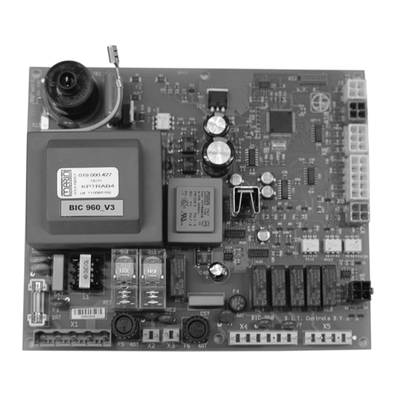
Page 3: Overview
OVERVIEW Overview BIC 960 Automatic gas firing device with Bus connection to TopTronic T / TopTronic ® ® 1..Gas pressure regulator 2 / 3... Gas valve 4..Fan 5 / 6... Boiler sensor with two sensor elements 7..Flue gas sensor (only with UltraGas ®... -
Page 4: Description Of Functions
General The BIC 960 automatic firing device is designed for use in a modulating gas boiler. There for a PWM fan is triggered by the automatic firing device. This fan has a supply voltage of 230V which is shut-off by an internal relay during downtimes in order to reduce stand-by losses. -
Page 5: Short Description Of The Functions Of The Bic 960 Automatic Firing Device
DESCRIPTION OF FUNCTIONS Short description of the functions of the BIC 960 automatic firing device Since the automatic firing device can only perform in connection with the heating controller, many common functions are already given via this. The list below contains only those characteristics which are integrated in the automatic... -
Page 6: Access To The Automatic Firing Device
DESCRIPTION OF THE PARAMETERS Access to the automatic firing device The boiler is operated in the same way as described in the operating instructions of the heating controller. The auto- matic firing device operating in the background can be accessed using a special menu tree on the heating controller. This menu allows access to the “BOILER CONTR”... - Page 7 DESCRIPTION OF THE PARAMETERS Parameter 5 (2AF/32773): Proportional part The Proportional part in heating operation is a boiler specific value (not plant specific) and must not be changed. Parameter 6 (2AG/32774): Integral part The Integral part in heating operation is a boiler specific value (not plant specific) and must not be changed. Parameter 7 (2AH/32775): Differential part The Differential part in heating operation is a boiler specific value (not plant specific) and must not be changed.
- Page 8 DESCRIPTION OF THE PARAMETERS Parameter 15 (2CA/32783): Gas pressure switch attached This parameter defines whether or not a gas pressure switch is attached to the boiler. Parameter 16 (2DA/32784): Water pressure sensor attached This parameter defines whether or not a water pressure sensor is attached to the boiler. Parameter 17 (2DB/32785): Water pressure warning If the water pressure falls below the value set under this parameter, “W:01”...
- Page 9 DESCRIPTION OF THE PARAMETERS Example: Example: Modulating Switch- False start Successful start operation Gas pressure External gas solenoid valve/ LGP Burner fan Int. Ignition Ext. Ignition Gas sole n oid valve Flame Time 25 s 30 s 25 s 10 s Par.37 Par.39 50 s 50 s...
- Page 10 “B:04” is shown. This blocking is no longer shown as of BIC 960 V.3. The ext. gas valve closes again as soon as the burner has switched off.
- Page 11 DESCRIPTION OF THE PARAMETERS Parameter 42 (2HD/32810): Summer operation (“summerkick”) Every 24 hours, the pump and/or shut-off valve turns on for the period of time entered under this parameter. Parameter 43 (2IA/32811): Ignition This parameter allows the following ignition options to be set: Ignition with internal ignition transformer Ignition with internal and external ignition transformer Ignition with external ignition transformer...
-
Page 12: Sensor Characteristic Curves
SENSOR CHARACTERISTIC CURVES Sensor characteristic curves The characteristic curve of the 12K NTC-Sensor Duplex screw-in sensor, which is used as the boiler sen sor, is iden- tical to the characteristic curve of the flue gas sensor, called the 12K NTC- Sensor screw-in sen sor. The characteristic curve of the pressure sensor module MCTH-1 (0..10 bar) is linear. -
Page 13: Display Of Information Via The Automatic Firing Device
DISPLAY OF INFORMATION VIA THE AUTOMATIC FIRING DEVICE Display of information via the automatic firing device Plant values can be consulted using the Info-key of the heating controller. The following values transmitted by the automatic firing device can be found in the Info-level of the UltraGas ®... -
Page 14: Monitoring Of Warnings And/Or Faults
B:04 Main gas valve (possibly LPG- valve)/ Heating room fan Appears during the waiting time (Parameter 39) until the burner starts. Blocking is no longer shown as of BIC 960 V.3. B:05 Water pressure outside of limits Appears if the water pressure exceeds or falls below the set limits (min: Parameter 19, max: Parameter 21). - Page 15 MONITORING OF WARNINGS AND/OR FAULTS Lock-outs: E:01 Flue gas sensor shorted (X8-2/X8-7) E:02 Flue gas sensor interrupted (X8-2/X8-7) E:03 Fan speed deviation on ignition. Appears when, after 4 start attempts the start is interrupted due to an excessive deviation of the actual speed from the setpoint speed setting.
-
Page 16: Operation Using A Laptop
Interfaces to BIC 960 The BIC 960 automatic firing device has a RS485 interface for communication with the heating controller. Connec- tion to a laptop occurs via the RS232 interface (X11). -
Page 17: Connections To The Bic960
CONNECTIONS TO THE BIC960 Connections to the BIC960 5-pin Phoenix-screw connector (Green) L, Pump/Fan N, Pump/Fan 2- pin Molex-Header (White) 5,08 mm (0.2’’) Pitch L, Pump N, Pump 2- pin Molex-Header (White) 5,08 mm (0.2’’) Pitch L, Fan N, Fan 6- pin Molex-Header (White) 5,08 mm (0,2’’) Pitch... -
Page 18: Ntc Protection
NTC PROTECTION 6- pin Molex-Minifit (White) Series 5566 24V DC Gas pressure switch Air pressure switch Blocking input Reset Security thermostat X10 4- pin Molex Minifit (Blue) Series 5566 I2C, earth Not occupied X11 4- pin Molex Minifit (White) Series 5566 RS232, RX RS232, TX RS232, 5V DC... -
Page 19: Frost Protection
FROST PROTECTION Frost protection Frost protection temperature Pump On 7 °C Frost protection temperature Pump Off 10 °C Switch-on temperature with active boiler frost protection 3 °C Switch-off temperature with active boiler frost protection 10 °C Water pressure Pressure warning Warning Blocking pressure min 0.5 bar... -
Page 20: Automatic Firing Unit Bic 960 - Parameter Lists
PARAMETER LISTS Automatic firing unit BIC 960 - Parameter lists 13.1 Generation overview (boiler) UltraGas (15) ® UltraGas (20) ® UltraGas (27) ® UltraGas (35) ® UltraGas (50) ® UltraGas (70) ® UltraGas (90) ® UltraGas (100) ® UltraGas (125) ®... - Page 21 PARAMETER LISTS UltraGas (15) ® UltraGas (15) ® UltraGas (20) ® UltraGas (27) ® UltraGas (20) ® UltraGas (35) ® UltraGas (50) ® UltraGas (27) ® UltraGas (70) ® UltraGas (90) ® UltraGas (35) ® UltraGas (100) ® UltraGas (125) ®...
-
Page 22: Generation Overview (Automatic Gas Firing Device)
PARAMETER LISTS 13.2 Generation overview (automatic gas firing device) UltraGas (15) ® UltraGas (20) ® UltraGas (27) ® UltraGas (35) ® UltraGas (50) ® UltraGas (70) ® UltraGas (90) ® UltraGas (100) ® UltraGas (125) ® UltraGas (150) ® UltraGas (200) ®... - Page 23 PARAMETER LISTS 13.3 10/20 - UG (15-90) Description 2AA Blocking temperature °C 2AC Maximum reference value °C 2AD Switch-off hysteresis above reference value °C 2AE Switch-on difference relating to tripping point °C 2AF Proportional part °C 6 2AG Integral part 2AH Differential part 2AI Reference value when bus interruption °C...
- Page 24 45 2LA Effect of the fault relay 46 2NA ADC/4 value at 0 bar ADC/4 value at 6 bar and BIC 960 V.2 47 2NB ADC/4 value at 10 bar and BIC 960 V.3 48 2IB Extended external ignition time...
- Page 25 PARAMETER LISTS 13.4 21 - UG (15-50) Description 2AA Blocking temperature °C 2AC Maximum reference value °C 2AD Switch-off hysteresis above reference value °C 2AE Switch-on difference relating to tripping point °C 2AF Proportional part °C 2AG Integral part 2AH Differential part Reference value when bus interruption °C Max.
- Page 26 Step modulation (0-> off, 1->increasing, 2-> increasing and decreasing) 2LA Effect of the fault relay 2NA ADC/4 value at 0 bar ADC/4 value at 6 bar and BIC 960 V.2 ADC/4 value at 10 bar and BIC 960 V.3 Extended external ignition time 2QA Reserve...
- Page 27 PARAMETER LISTS 13.5 30 - UG (15-90) Description 2AA Blocking temperature °C 2AC Maximum reference value °C 2AD Switch-off hysteresis above reference value °C 2AE Switch-on difference relating to tripping point °C 2AF Proportional part °C 2AG Integral part 2AH Differential part Reference value when bus interruption °C Max.
- Page 28 Step modulation (0-> off, 1->increasing, 2-> increasing and decreasing) 2LA Effect of the fault relay 2NA ADC/4 value at 0 bar ADC/4 value at 6 bar and BIC 960 V.2 ADC/4 value at 10 bar and BIC 960 V.3 Extended external ignition time 2QA Reserve...
- Page 29 PARAMETER LISTS 13.6 40/41 - UG (15-90) Parameter Description 32769 Blocking temperature °C 32770 Maximum reference value °C 32771 Switch-off hysteresis above reference value °C Switch-on difference relating to tripping 32772 °C point 2AF 32773 Proportional part °C 2AG 32774 Integral part 2AH 32775 Differential part 32776 Reference value when bus interruption °C...
- Page 30 32812 increasing and decreasing) 32813 Effect of the fault relay 32814 ADC/4 value at 0 bar ADC/4 value at 6 bar and BIC 960 V.2 32815 ADC/4 value at 10 bar and BIC 960 V.3 32816 Extended external ignition time...
- Page 31 PARAMETER LISTS 13.7 10 - UG (125-300) Description 2AA Blocking temperature °C 2AC Maximum reference value °C 2AD Switch-off hysteresis above reference value °C 2AE Switch-on difference relating to tripping point °C 2AF Proportional part °C 6 2AG Integral part 2AH Differential part 2AI Reference value when bus interruption °C...
- Page 32 44 2KM Step modulation (0-> off, 1->increasing, 2-> increasing and decreasing) 45 2LA Effect of the fault relay 46 2NA ADC/4 value at 0 bar ADC/4 value at 6 bar and BIC 960 V.2 47 2NB ADC/4 value at 10 bar and BIC 960 V.3...
- Page 33 PARAMETER LISTS 13.8 10 - UG (350-650) Description 2AA Blocking temperature °C 2AC Maximum reference value °C 2AD Switch-off hysteresis above reference value °C 2AE Switch-on difference relating to tripping point °C 2AF Proportional part °C 6 2AG Integral part 2AH Differential part 2AI Reference value when bus interruption °C...
- Page 34 44 2KM Step modulation (0-> off, 1->increasing, 2-> increasing and decreasing) 45 2LA Effect of the fault relay 46 2NA ADC/4 value at 0 bar ADC/4 value at 6 bar and BIC 960 V.2 47 2NB ADC/4 value at 10 bar and BIC 960 V.3...
-
Page 35: 11/20/21/30/31/41 - Ug (450-1000)
PARAMETER LISTS 13.9 11/20/21/30/31/41 - UG (125-400) Parameter Description 2AA 32769 Blocking temperature °C 2AC 32770 Maximum reference value °C 2AD 32771 Switch-off hysteresis above reference value °C 2AE 32772 Switch-on difference relating to tripping point °C 2AF 32773 Proportional part °C 6 2AG 32774 Integral part 2AH 32775 Differential part... - Page 36 45 2LA 32813 Effect of the fault relay 46 2NA 32814 ADC/4 value at 0 bar ADC/4 value at 6 bar and BIC 960 V.2 47 2NB 32815 ADC/4 value at 10 bar and BIC 960 V.3 48 2IB 32816 Extended external ignition time...
- Page 37 PARAMETER LISTS 13.10 11/20/21/30/31/41 - UG (450-1000) Parameter Description 2AA 32769 Blocking temperature °C 2AC 32770 Maximum reference value °C 2AD 32771 Switch-off hysteresis above reference value °C 2AE 32772 Switch-on difference relating to tripping point °C 2AF 32773 Proportional part °C 2AG 32774 Integral part 2AH 32775 Differential part...
- Page 38 (0-> off, 1->increasing, 2-> increasing and decreasing) 45 2LA 32813 Effect of the fault relay 46 2NA 32814 ADC/4 value at 0 bar ADC/4 value at 6 bar and BIC 960 V.2 47 2NB 32815 ADC/4 value at 10 bar and BIC 960 V.3...
-
Page 39: Compactgas (200-280)
PARAMETER LISTS 13.11 1 - CompactGas (200-280) ® Attention: The automatic gas firing device BIC 960 which must be used for the CompactGas boiler does not correspond with the ® BIC 960 used with the UltraGas boiler. ® Therefore when exchanging an automatic gas firing device on a CompactGas , an article No. - Page 40 44 2KM Step modulation (0-> off, 1->increasing, 2-> increasing and decreasing) 45 2LA Effect of the fault relay 46 2NA ADC/4 value at 0 bar ADC/4 value at 6 bar and BIC 960 V.2 47 2NB ADC/4 value at 10 bar and BIC 960 V.3...
- Page 41 4 205 503 / 14...
- Page 42 Conservation of Energy - Protection of the Environment...
Need help?
Do you have a question about the BIC 960 and is the answer not in the manual?
Questions and answers