Emerson Dixell XM670K Installing And Operating Instructions
Controllers for multiplexed cabinets
Hide thumbs
Also See for Dixell XM670K:
- Installing and operating instructions (10 pages) ,
- Installing and operating instructions (34 pages)
Advertisement
CONTROLLERS FOR MULTIPLEXED CABINETS
XM670K- XM679K
-MANUAL FOR THE SW REL. 4.2-
1. GENERAL WARNING
1.1
PLEASE READ BEFORE USING THIS MANUAL
This manual is part of the product and should be kept near the instrument for easy and quick
reference.
The instrument shall not be used for purposes different from those described hereunder. It cannot
be used as a safety device.
Check the application limits before proceeding.
Dixell Srl reserves the right to change the composition of its products, even without notice, ensuring
the same and unchanged functionality.
E
1.2
SAF
TY PRECAUTIONS
Check the supply voltage is correct before connecting the instrument.
Do not expose to water or moisture: use the controller only within the operating limits avoiding
sudden temperature changes with high atmospheric humidity to prevent formation of condensation
Warning: disconnect all electrical connections before any kind of maintenance.
Fit the probe where it is not accessible by the End User. The instrument must not be opened.
In case of failure or faulty operation send the instrument back to the distributor or to "Dixell S.r.l."
(see address) with a detailed description of the fault.
Consider the maximum current which can be applied to each relay (see Technical Data).
Ensure that the wires for probes, loads and the power supply are separated and far enough from
each other, without crossing or intertwining.
In case of applications in industrial environments, the use of mains filters (our mod. FT1) in parallel
with inductive loads could be useful.
2. BEFORE PROCEEDING
2.1
CHECK THE SW REL. OF THE XM679K
1.
Look at the SW rel. of XM679K printed on the label of the controller.
2.
If the SW release is 4.2 proceed with this manual otherwise contact Dixell to get the right manual.
3. GENERAL DESCRIPTION
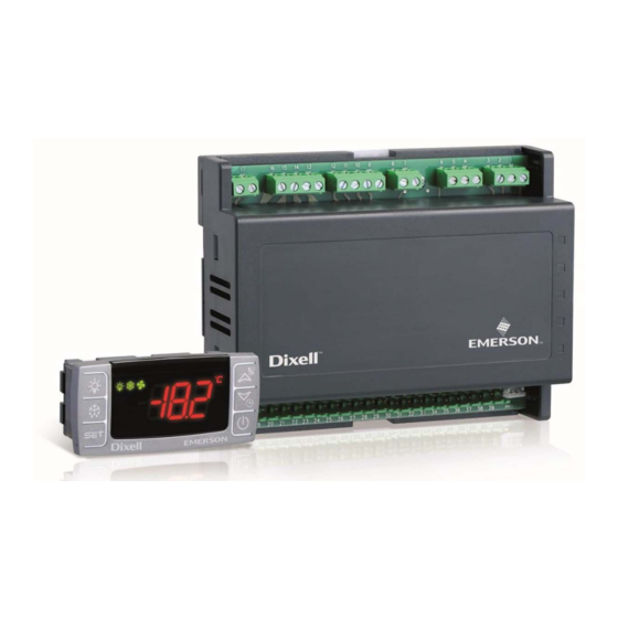
The XM670K/XM679K are high level microprocessor based controllers for multiplexed cabinets suitable
for applications on medium or low temperature. It can be inserted in a LAN of up to 8 different sections
which can operate, depending on the programming, as stand alone controllers or following the commands
coming from the other sections. The XM670K/XM679K are provided with 6 relay outputs to control the
solenoid valve, defrost - which can be either electrical or hot gas - the evaporator fans, the lights, an
auxiliary output and an alarm output and with one output to drive pulsed electronic expansion valves
(only XM679K). The devices are also provided with four probe inputs, one for temperature control, one
to control the defrost end temperature of the evaporator, the third for the display and the fourth can be
used for application with virtual probe or for inlet/outlet air temperature measurement. The model XM679K
is provided by other two probes that have to be used for superheat measurement and regulation. Finally,
the XM670K/XM679K are equipped with the three digital inputs (free contact) fully configurable by
parameters.
The instruments are equipped with the HOTKEY connector that permits to be programmed in a simple
way. Direct serial output RS485 ModBUS-RTU compatible permits a simple XWEB interfacing. RTC are
available as options. The HOTKEY connector can be used to connect X-REP display (Depending on the
model).
4. INSTALLATION AND MOUNTING
This device can operate without any user interface, but normal application is with Dixell CX660 keyboard.
Figure 1a
Figure 1c
5. WIRING DIAGRAM AND CONNECTIONS
5.1
IMPORTANT NOTE
XM device is provided with disconnectable terminal block to connect cables with a cross section up to 1.6 mm
all the low voltage connection: the RS485, the LAN, the probes, the digital inputs and the keyboard. Other inputs,
power supply and relay connections are provided with screw terminal block or fast-on connection (5.0 mm). Heat-
resistant cables have to be used.
1592023130 XM670K_XM679K GB r4.2 26.06.2017.docx
The CX660 keyboard shall be
mounted on vertical panel, in a 29x71
mm hole, and fixed using the special
bracket supplied as shown in fig. 1a/1b.
The temperature range allowed for
correct operation is 0 to 60°C. Avoid
places subject to strong vibrations,
corrosive gases, excessive dirt or
humidity.
The same recommendations apply to
probes. Let air circulate by the cooling
holes.
Figure 1b
Before connecting cables make sure the power supply complies with the instrument's requirements. Separate the
probe cables from the power supply cables, from the outputs and the power connections. Do not exceed the
maximum current allowed on each relay, in case of heavier loads use a suitable external relay. N.B. Maximum
current allowed for all the loads is 16A. The probes shall be mounted with the bulb upwards to prevent damages
due to casual liquid infiltration. It is recommended to place the thermostat probe away from air streams to correctly
measure the average room temperature. Place the defrost termination probe among the evaporator fins in the
coldest place, where most ice is formed, far from heaters or from the warmest place during defrost, to prevent
premature defrost termination.
5.2 XM670K – ALL POWER SUPPLY
5.3 XM679K – 230VAC VALVES
5.4 XM679K – 24VAC VALVES
NOTE: the jumper indicated as JMP is inside the case of the controller. This jumper
has to be closed only in case of driving 24Vac valve.
5.5
KEYBOARD DISPLAY CX660
The XM670/679K board can operate also without keyboard.
5.6
SYNCHRONIZED DEFROST – MAXIMUM 8 SECTIONS
Follow next steps to create a LAN connection, which is a necessary condition to perform synchronized defrost
(also called master-slave functioning):
1)
connect a shielded cable between terminals [38] [-] and [39] [+] for a maximum of 8 sections;
2)
the Adr parameter is the number to identify each electronic board. Address duplication is not permitted,
in this case the synchronized defrost and the communication with monitoring system is not guaranteed (the
Adr is also the ModBUS address). For example, a correct configuration is the following:
If the LAN is well connected, the green LED will be ON. If the green LED blinks then the connection is
wrongly configured.
The max distance allowed is 30m
for
2
XM670K - XM679K
Polarity:
Terminal [34] [-]
Terminal [35] [+]
Use twisted shielded cable
AWG 18 or less in case of long
distance.
Max distance: 30m
1/10
Advertisement
Table of Contents


Need help?
Do you have a question about the Dixell XM670K and is the answer not in the manual?
Questions and answers