Aprilaire 60 Safety And Installation Instructions Manual
Automatic humidifier control
Hide thumbs
Also See for 60:
- User manual ,
- Safety and installation instructions manual (16 pages) ,
- Operating instructions manual (10 pages)
Advertisement
Quick Links
All manuals and user guides at all-guides.com
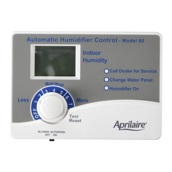
Model 60 shown.
utomatic
Digital Humidifier Control
Model 60 & 62
Safety and Installation Instructions
RE D COMPLETE INST LL TION INSTRUCTIONS
ND TEMPL TE BEFORE ST RTING INST LL TION.
W RNING
TTENTION INST LLER: This product must be
installed by a qualified heating and air conditioning
contractor. Failure to do so could result in serious
injury from electrical shock.
Advertisement

Related Manuals for Aprilaire 60


Summary of Contents for Aprilaire 60
- Page 1 All manuals and user guides at all-guides.com Model 60 shown. utomatic Digital Humidifier Control Model 60 & 62 Safety and Installation Instructions RE D COMPLETE INST LL TION INSTRUCTIONS ND TEMPL TE BEFORE ST RTING INST LL TION. W RNING...
- Page 2 All manuals and user guides at all-guides.com W RNING T BLE OF CONTENTS Hazardous Voltage can cause serious injury Getting Started ........page 3 from electric shock.
- Page 3 TO HVAC SENSOR EQUIPMENT Model 500 Series, 600 Series and 700 Series COMMUNICATION HEAT SIGNAL SOLENOID humidifiers in areas with WITH APRILAIRE FROM HVAC CONTROL 8570 THERMOSTAT EQUIPMENT OUTPUT very hard water. The indicator will light after 24 VAC FROM FAN SIGNAL 300 hours of operation.
- Page 4 All manuals and user guides at all-guides.com The Model 62 shipped with the Model 800 Steam Humidifier is INST LL TION factory set to “OFF”. The Model 62 does not have the “Change Water Panel” light on the Control. The Canister Change indicator STEP 1: Mount the Humidifier Control for the Model 800 is on the humidifier.
- Page 5 All manuals and user guides at all-guides.com DUCT (FIBER BO RD) MOUNT: C UTION fter location for Control is selected, cut a rectangular hole in Controller damage or malfunction may occur if the duct board, no smaller than 6-9/16 inches long by 4-3/8 installation instructions are not followed.
- Page 6 All manuals and user guides at all-guides.com STEP 2: Determine Location for and Mount Outdoor Figure E – Fiber Board Duct Mount Temperature Sensor The location of the Outdoor Temperature Sensor must meet these three requirements: CONTROL BOARD 1. Must be mounted on North, East or West side of house out of direct sunlight.
- Page 7 All manuals and user guides at all-guides.com STEP 4: Route the Wire from Control to Sensor STEP 3: lternate Location for Outdoor Temperature Sensor Run wire to the outdoor temperature sensor. Sensor is accurate with lead lengths up to 300 ft. When mounting the Outdoor Temperature Sensor in an intake air duct the turn the Blower ctivation switch (see Figure J) to C UTION...
- Page 8 AUTO/MANUAL MODE SWITCH humidifier solenoid valve wires. Connect the other solenoid valve wire to the other “H” terminal. • Wire “R” and “C” on the Model 60 to “R” and “C” on the BLOWER ACTIVATION SWITCH 90-1236B furnace terminal strip.
- Page 9 All manuals and user guides at all-guides.com • Wire “W” on the Model 60 to “W” on the furnace terminal strip. STEP 7: Model 62 wiring for Model 800 Series Steam Humidifier and Model 60 Wiring for Model 700* Series •...
- Page 10 All manuals and user guides at all-guides.com SYSTEM CHECKOUT Figure L – Model 62 wiring for Model 800 Series Steam Humidifier and Model 60 Wiring for Model 1. Replace the cover by snapping it into the Humidifier Control 700* Series ( lmond Housing) Humidifiers base.
- Page 11 All manuals and user guides at all-guides.com Blower ctivation Test TROUBLESHOOTING GUIDE • Deactivate HV C system or heat pump. • Turn knob to OFF. SYMPTOM • Set switch to Blower ctivation ON. Call Dealer For Service Light Flashing (see Figure M). •...
- Page 12 All manuals and user guides at all-guides.com T BLE 1 TROUBLESHOOTING PROCEDURE (CONTINUED) Outdoor Temperature (°F) Resistance (k ) ±10 3. Rotate Humidifier Control knob to the “Test/Reset” position. 231.8 fter 5 seconds, the green “Humidifier On” light will blink, 163.4 resetting the error.
- Page 13 All manuals and user guides at all-guides.com SYMPTOM SYMPTOM Humidifier does not operate in “Test/Reset” mode. Yellow “Change Water Panel” light is blinking (see Figure M). TROUBLESHOOTING PROCEDURE TROUBLESHOOTING PROCEDURE • Check wiring diagrams for correct Humidifier Control Check the condition of the Water Panel and replace it if installation.
- Page 14 Humidifier operates only in “Test/Reset” mode. Humidifier operates constantly. • If outdoor temperature is greater than 60°F or less than • If the humidity level in the home is less than the Humidifier -30°F, the Humidifier Control will only operate in the Control knob setting and there is a continuous fan call or “Test/Reset”...
- Page 15 All manuals and user guides at all-guides.com SYMPTOM Humidifier or Humidifier Control “chatters” or clicks On and Off rapidly. TROUBLESHOOTING PROCEDURE • Check for steady 22 V C to 30 V C across the “R” and “C” terminals of the Humidifier Control with a voltmeter. •...
Need help?
Do you have a question about the 60 and is the answer not in the manual?
Questions and answers