Table of Contents
Advertisement
TEMPTRAC INTERFACE GUIDE, GATEWAY SETUP AND POINTS LIST
Installation and interface must be performed by a qualified controls technician.
IMPORTANT: THIS MANUAL CONTAINS INFORMATION REQUIRED FOR INSTALLATION, INTERFACE AND
CONFIGURATION OF THIS EQUIPMENT. READ AND FOLLOW THE INFORMATION IN THIS MANUAL AND ALL
OTHER PROVIDED INSTRUCTIONS, LABELS AND MARKINGS BEFORE INSTALLING, OPERATING OR SERVICING
THIS UNIT.
Contents
OVERVIEW OF INTERFACE METHODS: ................................................................................................. 2
TEMPTRAC PROTOCOL ........................................................................................................................... 4
ITEMS REQUIRED FOR GATEWAY INTERFACE: ................................................................................... 4
ITEMS REQUIRED FOR MODBUS DIRECT INTERACE: ......................................................................... 4
IDENTIFY EQUIPMENT: ............................................................................................................................. 5
WIRING BAS TO GATEWAY AND THEN GATEWAY TO TEMPTRAC: .................................................. 6
WIRING OF TEMPTRAC TO BAS (Direct, no Gateway): ........................................................................... 7
GATEWAY CONFIGURATION CONNECTION: ........................................................................................ 7
CONFIGURE GATEWAY DIP SWITCHES: ............................................................................................... 8
CONFIGURE THE GATEWAY USING THE HTML INTERFACE: ............................................................. 9
CONFIRM OPERATION: ........................................................................................................................... 10
TROUBLESHOOTING GATEWAY: .......................................................................................................... 10
HOOKUP OVERVIEW: .............................................................................................................................. 11
APPLICATION SPECIFICS: ...................................................................................................................... 12
POINTS LIST: ............................................................................................................................................ 16
TYPICAL POINTS: ..................................................................................................................................... 16
ALL POINTS INCLUDING ADVANCED: ................................................................................................... 18
ADVANCED MODBUS LIST: .................................................................................................................... 25
TO THE INSTALLER / CONTROLS INTEGRATOR: After installation and integration, these instructions must be
given to the equipment user or left near the appliance.
SPECIAL INSTRUCTIONS TO THE OWNER: Retain this manual for future reference. These instructions contain
important integration information that will help you in maintaining and operating this appliance.
PVI INDUSTRIES, LLC - Fort Worth, Texas 76111 - Web
www.pvi.com
Page 1 of 30
- Phone 1-800-433-5654
PV7069-T 03/17
Part number 129209
Advertisement
Table of Contents

Related Manuals for PVI Industries TempTrac

Summary of Contents for PVI Industries TempTrac
-
Page 1: Table Of Contents
ITEMS REQUIRED FOR GATEWAY INTERFACE: ................... 4 ITEMS REQUIRED FOR MODBUS DIRECT INTERACE: ................. 4 IDENTIFY EQUIPMENT: ..........................5 WIRING BAS TO GATEWAY AND THEN GATEWAY TO TEMPTRAC: ..........6 WIRING OF TEMPTRAC TO BAS (Direct, no Gateway): ................7 GATEWAY CONFIGURATION CONNECTION: ..................7 CONFIGURE GATEWAY DIP SWITCHES: .................... -
Page 2: Overview Of Interface Methods
TEMPTRAC INTERFACE GUIDE, GATEWAY SETUP AND POINTS LIST OVERVIEW OF INTERFACE METHODS: This document is a quick reference for connecting the TempTrac water heater / boiler control to a Building Automation System (BAS). Direct connection via MODBUS RTU or using a gateway to interface to protocols other than MODBUS RTU are the methods covered in this manual. - Page 3 The MODBUS adapter is an orange dongle with 2 green screw terminals attached to an 8 inch cable that plugs into the back of the TempTrac at a white header. This can be an option installed on heater, or it may be a separate line item part.
-
Page 4: Temptrac Protocol
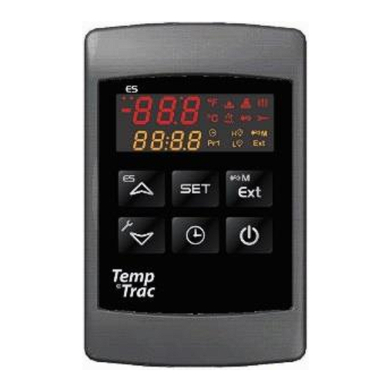
The PVI gateway does provide optional biasing (default) and can provide a termination resistor, if required. ITEMS REQUIRED FOR GATEWAY INTERFACE: One or more water heaters with a TempTrac control (red/orange LED display with 6 tactile buttons) including the RS-485 adapter. -
Page 5: Identify Equipment
TempTrac is mounted on the control panel of the equipment. On the back side of the TempTrac is a white header. The RS-485 adapter plugs into this with a 8 inch cable. The orange adapter has 2 green terminals labeled (+) &... -
Page 6: Wiring Bas To Gateway And Then Gateway To Temptrac
TEMPTRAC INTERFACE GUIDE, GATEWAY SETUP AND POINTS LIST WIRING BAS TO GATEWAY AND THEN GATEWAY TO TEMPTRAC: Each gateway has 3 connection points. The 6 position terminal block contains connection for power and MODBUS RTU (going to heaters). The Ethernet port is for configuration, BACNET IP, or MODBUS TCP. -
Page 7: Wiring Of Temptrac To Bas (Direct, No Gateway)
WIRING OF TEMPTRAC TO BAS (Direct, no Gateway): The back side of the TempTrac has a white header with an 8 inch cable, connecting to an orange adapter module with 2 green terminals labeled (+) & (-). This is the RS-485 Modbus connection point. -
Page 8: Configure Gateway Dip Switches
TEMPTRAC INTERFACE GUIDE, GATEWAY SETUP AND POINTS LIST CONFIGURE GATEWAY DIP SWITCHES: The ON position is toward the center of the module, and OFF is toward the edge of the module. Only the BACNET gateway requires dip switch settings. The BACNET gateway is used for MODBUS TPC also. -
Page 9: Configure The Gateway Using The Html Interface
CONFIGURE THE GATEWAY USING THE HTML INTERFACE: This section will provide the parameters required for the TempTrac control. For more details of the gateway, consult the gateway manual. Connect your computer’s Ethernet port to the Ethernet port of the gateway. -
Page 10: Confirm Operation
Confirm gateway has been configured TX flashing, RX not flashing o Gateway is talking to TempTrac, but not getting response from TempTrac. Confirm wiring, confirm TempTrac is configured to proper address, Baud, Parity, Stop bits. Verify polarity of all connections: Set a Digital Volt Meter to read DC Volts. -
Page 11: Hookup Overview
TEMPTRAC INTERFACE GUIDE, GATEWAY SETUP AND POINTS LIST HOOKUP OVERVIEW: BACNET MSTP or LONWORKS Power Adapter BACNET MSTP LONWORKS To heaters with TempTrac BACNET IP or MODBUS TCP Power Adapter BACNET IP MODBUS TCP To heaters with TempTrac MODBUS RTU Direct Connect... -
Page 12: Application Specifics
TEMPTRAC INTERFACE GUIDE, GATEWAY SETUP AND POINTS LIST APPLICATION SPECIFICS: Each product that uses the TempTrac control may have subtle differences. The following products address the important information regarding each device. Conquest 100 Gallon (199 – 299) & 130 gallon 399: (Smaller Conquest) - Page 13 TEMPTRAC INTERFACE GUIDE, GATEWAY SETUP AND POINTS LIST Centauri Boiler, Centauri Plus Boiler, VT3 Boiler: Model Numbers: All Centauri, Centauri Plus and VT3 Boilers Probe 1: This temperature is displayed in yellow in the lower section of the display. With SSBCO option, this probe is located in the top of the boiler. Without this option, the probe is shipped uninstalled and should be installed in the BHWR piping to read the temperature of the water entering the boiler.
- Page 14 TEMPTRAC INTERFACE GUIDE, GATEWAY SETUP AND POINTS LIST M3 Boiler Probe 1: Is in the top of the tank, and controls the burner. Provides outlet temperature. Probe 2: Is wired but lose and field installed in the boiler HWR piping.
- Page 15 Other Equipment and Equipment Custom features: Reference supplied wiring diagram and the I & O Manual. Contact PVI for additional information. Below is a list of other products that can use the TempTrac controller: Quickdraw Water to water Storage EZ PLATE STORAGE...
-
Page 16: Points List
Deg_F Probe that provides control of heating. Location can vary depending on equipment and application. See section that discussed the various equipment to determine actual location of probe. Connection on TempTrac is green screw terminals 14 and common 17. Page 16 of 30... - Page 17 Digital Input #2 alarm. On some products, this is a general failure to operate alarm. See product specific information. This is Bit 11 of the ALARM STATUS ALL word. Flashes ‘AL2’ or ‘LP’ on TempTrac display. In BACNET and LONWORKS, this is broken out into a state logic point.
-
Page 18: All Points Including Advanced
Digital Input #3 alarm. On some products, this is a general failure to operate alarm. See product specific information. This is Bit 12 of the ALARM STATUS ALL word. Flashes ‘AL3’ or ‘HP’ on TempTrac display. In BACNET and LONWORKS, this is broken out into a state logic point. - Page 19 Deg_F Optional probe on some devices, usually installed on most devices. If installed and enabled, returns the temperature of the probe in degrees F. Connection on TempTrac is green screw terminals 15 and common 17. Probe 3 Read Only...
- Page 20 TEMPTRAC INTERFACE GUIDE, GATEWAY SETUP AND POINTS LIST ALL POINTS INCLUDING ADVANCE: Probe 1 C Read Only Controlling Probe Degrees C MODBUS BACNET Probe1_C 25790 Deg-C LONWORKS Special BACNET point that converts the Probe value to degrees C in the gateway. Not available in LONWORKS or MODBUS.
- Page 21 BACNET TT_2on 85600 LONWORKS nvoTT_2on_ # nviTT_2on_# TempTrac relay output spade 6 & 7. 0= Force relay off, 1=Force relay ON, 2= Auto (operates from thermostat functions). Output #3 Mode Read/Write Output #2 mode, ON, OFF, AUTO MODBUS Holding Register...
- Page 22 Probe 1 alarm. This can be a disconnected, open or shorted probe. This will shut down heating operation. This is Bit 2 of the ALARM STATUS ALL word. Flashes ‘P1’ on TempTrac display. In BACNET and LONWORKS, this is broken out into a state logic point.
- Page 23 Digital Input #1 alarm. This is typically not implemented. Refer to product specific details for information on this alarm. This is Bit 10 of the ALARM STATUS ALL word. Flashes ‘AL1’ on TempTrac display. In BACNET and LONWORKS, this is broken out into a state logic point.
- Page 24 Maintenance Alarm. This is enabled when the time on ou1 is greater than the value in oP1. Flashes ‘Nn1’ on TempTrac display. Bit #13 of Alarms. In BACNET and LONWORKS, this is broken out into a state logic point. For MODBUS ALARMS && 0x2000 = 0x2000 Alarm is active. = 0x0000 Alarm is not active.
-
Page 25: Advanced Modbus List
TEMPTRAC INTERFACE GUIDE, GATEWAY SETUP, AND POINTS LIST ADVANCED MODBUS LIST: The following is the direct MODBUS interface addresses. Descriptions of most to the MODBUS parameters are listed in the correlating TYPICAL POINTS defined previously. Many MODBUS parameters are not supported in the gateway interface. - Page 26 TEMPTRAC INTERFACE GUIDE, GATEWAY SETUP, AND POINTS LIST Hex Add Description Label Firm Range Modbus Register Version X÷Y Level Level base 0 40000+ Set point1 0x300 0.3 & 0.5 LS1÷US1 Set point2 0x301 0.3 & 0.5 LS2÷US2 Set point3 0x302 0.3 &...
- Page 27 TEMPTRAC INTERFACE GUIDE, GATEWAY SETUP, AND POINTS LIST Maximum shift of St1 0x321 0.3 & 0.5 -100÷100°F Outdoor temperature threshold to open all the loads 0x322 0.3 & 0.5 -40÷230°F Differential for restart working of controller 0x323 0.3 & 0.5 -45 ÷...
- Page 28 TEMPTRAC INTERFACE GUIDE, GATEWAY SETUP, AND POINTS LIST Current hour 0x338 0.3 & 0.5 0 ÷ 23 Current minute 0x339 0.3 & 0.5 0 ÷ 59 Current day 0x33A 0.3 & 0.5 Sun ÷ SAt ENERGY SAVING TIMES Energy saving start on Sunday 0x33B 0.3 &...
- Page 29 TEMPTRAC INTERFACE GUIDE, GATEWAY SETUP, AND POINTS LIST Serial address 0x359 0.3 & 0.5 0÷247 Parameter map code always = 1 0x35A 0.3 & 0.5 readable only Software release 5 = V0.5, 3 = V0.3 0x35B 0.3 & 0.5 readable only...
- Page 30 TEMPTRAC INTERFACE GUIDE, GATEWAY SETUP, AND POINTS LIST ALARM 2 (Lockout, stops heating) Input 2, Flash AL2 & Lguage & valve= 2048 or 0x1000 0xD00 3329 bit # 11 or 12th bit ALARM 3 (Lockout, stops heating) Input 3/ALMMB/ALOAF, beep, Flash AL3 & Hguage & valve...
Need help?
Do you have a question about the TempTrac and is the answer not in the manual?
Questions and answers