Table of Contents
Advertisement
Quick Links
Advertisement
Table of Contents

Subscribe to Our Youtube Channel
Related Manuals for Alphatron AlphaPilot MFM

Summary of Contents for Alphatron AlphaPilot MFM
- Page 1 AlphaPilot MFM Operation Manual www.alphatronmarine.com...
-
Page 2: Table Of Contents
IV. About the manual .......................... 15 Intended readers ..........................15 Manual overview ..........................15 Related documents ..........................15 Introduction ........................... 16 AlphaPilot MFM control unit ......................17 Operating modes ........................... 21 Introduction ........................... 21 Standby (S) mode ........................23 Manual (M) mode ........................23 Auto (A) control mode ...................... - Page 3 3.7.3 Steering in Override (O) control mode ................31 Track (T) control modes ......................32 3.8.1 Introduction ........................32 3.8.2 Track (T) control mode, TCS category A, B ..............33 3.8.3 Track (Tn) control mode, TCS category C ..............37 Rate of Turn (R) control mode ....................
- Page 4 5.3.1 Submenu ‘Set Devices’ ....................53 5.3.2 Submenu ‘Panel Settings’ ....................57 Menu ‘Installation’ ........................ 58 Alarm log ............................59 Alarms, warnings, and cautions ....................60 Appendices ............................64 Appendix A: Alphatron MFM Alerts ....................64 4 | Introduction...
-
Page 5: Preface
The AlphaPilot MFM control unit is the main control module of the AlphaPilot MFM system. It is used for control and monitoring of autopilot operation, setting vessel heading or rudder angle, selection of autopilot operating modes. -
Page 6: Revision History
Revision History Revision Date Description Author 14-06-2018 First release J. Kreeft 03-09-2018 3.1: Clarification on Track control mode. J. Kreeft 4.2: No control message added. 5.3.2: Updated ‘Active Palette’ and ‘< Skin Selection >’ Removed INS references Appendix A: Completely revised Appendix. 11-09-2018 Replaced image on page 28, 29, 32, 36, 38, 41, 58, 59, J. -
Page 7: Glossary
Glossary The glossary contains a list of abbreviations and a list of definitions. Abbreviations Abbreviations as used in this manual are explained in the table below. AUTO Automatic (‘Heading Control mode’) Main processor (inside the MCU Box) Bearing to waypoint Category Course over ground Digital Nautical Charts... -
Page 8: Definitions
AlphaPilot MFM Alphatron brand name for the heading control system Assisted turn Manoeuvre of a vessel from one straight leg to the next automatically controlled by a pre-set radius or rate of turn but not based on the vessel's position. - Page 9 COG (Course Over COG is the actual direction of progress of a vessel, between two Ground) points, with respect to the surface of the earth. The vessel’s heading may differ from the COG because of wind, tide and currents. Course A vessel's course is the cardinal direction along which the vessel is to be steered.
- Page 10 Main conning position Place on the bridge with a commanding view providing the necessary information and equipment for the conning officer to carry out his functions. Main steering gear The machinery, rudder actuators, steering gear power units, if any, and ancillary equipment and the means of applying torque to the rudder stock (e.g.
- Page 11 TCS (Track Control System designed to keep a vessel on a pre-determined track System) throughout its passage. Track Control systems must be interfaced with an electronic position fixing system. SOLAS Regulation 19, 2.8.2 requires Heading Control or Track Control Systems to be fitted to all vessels of 10000 GT and upward.
-
Page 12: Safety Information
Failure to comply with the precautions or with specific dangers, warnings, and cautions elsewhere in this manual violates safety standards of design, manufacture, and intended use of the equipment. ALPHATRON MARINE assumes no liability for the customer's failure to comply with these requirements. - Page 13 Immediately turn off the power and disconnect the power supply cable if the equipment is generating any smoke or odour or is overheated. WARNING Immediately inform your local service agent of the symptom to have it repaired. Prolonged equipment operation under such a condition can cause a fire or electric shock.
-
Page 14: Warranty
Installation of this product shall only be done by a certified installation company NOTICE approved by either ALPHATRON MARINE or by an official ALPHATRON MARINE distributor. Acting otherwise will void the warranty. This product contains no operator serviceable parts. Service and repair shall only be NOTICE carried out by personnel trained and certified by ALPHATRON MARINE. -
Page 15: About The Manual
About the manual Intended readers This manual is an operation manual for the AlphaPilot MFM system and control unit. The manual is intended for end users. Manual overview This manual has the following chapters: • Introduction contains a description about the AlphaPilot MFM system. -
Page 16: Introduction
The AlphaPilot MFM control unit is the main operator control unit of the AlphaPilot MFM system. It is used for control and monitoring of autopilot operation, setting vessel heading or rudder angle, selection of autopilot operating modes. -
Page 17: Alphapilot Mfm Control Unit
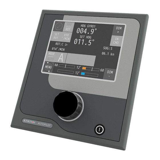
2 AlphaPilot MFM control unit The AlphaPilot MFM control unit has a touch screen display, a rotary knob, and a power button: The touch screen display shows information such as heading, current mode and settings, and alerts. The touch screen display is also used to set parameters (see Figure 2 on page 18). - Page 18 Figure 2: AlphaPilot MFM control unit - Displayed information Item Description Alert symbol Symbol for active alarm or notification. For detailed descriptions of alerts, see section ‘Alarms, warnings, and cautions’ on page 16. Actual heading Actual heading taken from compass source.
- Page 19 Increase brightness level of all modules simultaneously. brightness level In command Shows if the AlphaPilot MFM control unit is in command. Also used for control handover. See section ’Control handover’ on page 48. Source for Source from which the speed is taken. SOG value can be received from sensor actual speed (i.e.
- Page 20 NOTE: Some control modes (e.g. CTS pilot (C) and Wind vane (V) control mode) use their own steering method (which are strongly defined in the Autopilot software regardless of this setting). Table 1: Description of AlphaPilot MFM displayed information 20 | AlphaPilot MFM control unit...
-
Page 21: Operating Modes
3 Operating modes 3.1 Introduction The operating modes are displayed on the AlphaPilot MFM control unit (see Figure 2 on page 18) and explained in this section. Symbols are used to clearly indicate the active autopilot operating mode. To enable a heading control mode, press the ‘MODE|AUTO’ button to change the control mode (the identifier of the next available control mode appears on the display). - Page 22 * The control mode may not be available. It can be enabled or disabled by a service engineer (see AlphaPilot MFM Installation Manual). ** Track control mode combines an ECDIS with the Autopilot. The navigator can program a voyage plan into the ECDIS that contains one or more tracks.
-
Page 23: Standby (S) Mode
3.2 Standby (S) mode Autopilot is not operating for vessel heading control. Figure 3: AlphaPilot MFM control unit - S mode Autopilot will go into Standby (S) mode automatically when the Mode Switch is switched to the ‘NFU’ position. 3.3 Manual (M) mode Autopilot is not operating for vessel heading control. -
Page 24: Auto (A) Control Mode
The following information is displayed in Auto (A) control mode: actual heading, pre-set heading, actual speed, actual ROT in degrees per minute or actual RAD in nautical miles, rudder(s) order, rudder(s) feedback, and steering method. Figure 5: Auto (A) mode on AlphaPilot MFM control unit 24 | Operating modes... -
Page 25: Enable Auto (A) Control Mode
NOTE: While in Auto (A) control mode, the system continuously checks for the availability and quality of heading and speed information. In case of no heading data, the audible and visual alert is generated and ‘SWITCH TO MANUAL’ prompt message appears on the display. NOTE: Warning message ‘ROT/RAD UNREACHABLE’... -
Page 26: Low Speed Heading Control Mode
3.5 Low Speed Heading Control mode 3.5.1 Introduction AlphaPilot MFM can operate with one or two tunnel thrusters and support the ‘Low Speed Heading Control’ mode (sub mode of Auto mode); Alert ‘LOW SPEED FOR AUTO’ is disabled, and one or two tunnel thrusters assist in vessel control. -
Page 27: Enable Low Speed Heading Control Mode
3.5.2 Enable Low Speed Heading Control mode While in Standby (S) mode, change the ‘AP Type’ parameter in the menu ‘Parameters’: Figure 7: Menu ‘Parameters’ AP Type ‘AP’ (left), AP Type ‘TT’ (right) ‘AP‘ : Low Speed Heading Control is disabled. Bow and/or stern thruster(s) are not used. ‘TT’... -
Page 28: Steering In Low Speed Heading Control Mode
3.5.3 Steering in Low Speed Heading Control mode NOTE: In case of a single failure during operation in ‘Low Speed Heading Control’ mode, the AlphaPilot MFM will use the following procedure to keep a ‘SET HDG’ as accurate as possible: Single thruster failure Autopilot uses the second thruster (if available) and single, linked, or independent rudders –... -
Page 29: Dodge (D) Mode
NOTE: ‘Rudder Limit’, ‘SET ROT’ and ‘SET RAD’ parameters are not used during operation in Dodge (D) control mode. Figure 9: Dodge (D) mode on AlphaPilot MFM control unit 3.6.2 Enable Dodge (D) control mode Press the ‘MODE|AUTO’ button to change the control mode (the identifier of the next available control mode appears on the display). -
Page 30: Override (O) Control Mode
NOTE: For vessels with two independent rudders; In Override (O) control mode, all control operations for both rudders are implemented synchronously. NOTE: ‘Rudder Limit’, ‘SET ROT’ and ‘SET RAD’ are not used during operation in Override (O) control mode. Figure 10: Override (O) mode on AlphaPilot MFM control unit 30 | Operating modes... -
Page 31: Enable Override (O) Control Mode
Autopilot goes into selected mode (the ‘O’ symbol appears in ‘Operating mode’ field on the display). The AlphaPilot MFM control unit generates time limited audible signal and displays a warning message ‘OVERRIDE’. NOTE: After using the Override (O) control mode, the Autopilot must be manually returned to Auto (A) mode;... -
Page 32: Track (T) Control Modes
3.8 Track (T) control modes 3.8.1 Introduction Track (T) control mode (also referred to as ‘Track steering’) combines an ECDIS with the Autopilot. The navigator can program a voyage plan into the ECDIS that contains 1 or more tracks. The TCS (Track Control System) is used together with the input from the sensors for position, course and speed and is designed to keep the vessel on the plotted route. -
Page 33: Track (T) Control Mode, Tcs Category A, B
(XTD and BTW) from an external TCS (Track Control System) and operates as a track controller. In this mode, the user is requested to acknowledge waypoints. Figure 11: Track (T) mode on AlphaPilot MFM control unit WARNING This functionality is not compliant to the SOLAS convention unless approved as part of a TCS category A, B. - Page 34 Press the ‘MODE|AUTO’ button to change the control mode (the identifier of the next available control mode appears on the display). When the Track (T) control mode is shown, push the rotary knob, and the AlphaPilot MFM system goes into selected mode (the ‘T’ symbol appears in ‘Operating mode’ field on the display).
- Page 35 Steering in Track (T) control mode 3.8.2.3.1 Confirm a new waypoint External TCS (ECDIS/ECS) switches over track waypoints. At changing the waypoint, AlphaPilot MFM control unit requests heading change confirmation for turning to a new leg. Push the rotary knob to confirm a new waypoint.
- Page 36 RAD method in Track (T) control mode. Turn radiuses can be set for any WP in the ECDIS, and the corresponding ‘SET RAD’ parameter – in the operating menu ‘Parameters’ or using ‘ROT/RAD’ button and rotary knob on the AlphaPilot MFM control unit.
-
Page 37: Track (Tn) Control Mode, Tcs Category C
Automatic steering by means of track control on straight legs and turns (TCS category C); Autopilot receives information from an external TCS and operates as a track controller. Figure 15: Track (Tn) mode on AlphaPilot MFM control unit Figure 16: Track (Ti) mode on AlphaPilot MFM control unit NOTE: Track (Tn) control mode may not be available, as it can be enabled or disabled (see AlphaPilot MFM Installation Manual). - Page 38 NOTE: In Track (Tn) control mode, a ‘CHANGE SPEED SOURCE’ alert is generated when a manual speed was set before the activation of the Track (T) control mode. Switch back into Standby (S) mode and change a speed source to LOG or SOG in the submenu ‘Set devices’ of the menu ‘Advanced’. NOTE: ‘Rudder Limit’, ‘SET ROT’...
-
Page 39: Rate Of Turn (R) Control Mode
The following information is displayed in Rate of Turn (R) control mode: actual heading, actual speed, ROT order, actual ROT (in degrees per minute), rudder(s) order, rudder(s) feedback. Figure 18: Rate of Turn (R) mode on AlphaPilot MFM control unit 39 | Operating modes... -
Page 40: Enable Rate Of Turn (R) Mode
3.9.2.2 Enable Rate of Turn (R) mode from AlphaPilot MFM control unit Press the ‘MODE|AUTO’ button to change the control mode (the identifier of the next available control mode appears on the display). When the Rate of Turn (R) control mode is shown, push the rotary knob, and the Autopilot goes into selected mode (the ‘R’... -
Page 41: Cts Pilot (C) Control Mode
NOTE: CTS pilot (C) control mode may not be available, as it can be enabled or disabled (see AlphaPilot MFM Installation Manual). NOTE: AlphaPilot MFM uses RAD in CTS pilot (C) control mode. ROT is not used during operation in CTS pilot (C) control mode. -
Page 42: Enable Cts Pilot (C) Control Mode
ROT in degrees per minute or actual RAD in nautical miles, rudder(s) order, rudder(s) feedback. Figure 20: CTS pilot (C) mode on AlphaPilot MFM control unit NOTE: COG value can be received from sensor (i.e. COG:S) or it can be calculated (i.e. COG:C). -
Page 43: Wind Vane (V) Control Mode
This control mode is not compliant to the SOLAS convention. Automatic steering by the pre-set relative wind angle. A wind sensor is required. NOTE: AlphaPilot MFM uses ROT in Wind vane (V) control mode. RAD is not used during operation in Wind vane (V) control mode. -
Page 44: Enable Wind Vane (V) Control Mode
Relative Wind angle deviates momentary from the pre-set Relative Wind Angle beyond a pre-set limit. After that the AlphaPilot MFM is switched automatically to the Auto (A) control mode and alarm ‘WINDVANE FAIL’ and a prompt message ‘SWITCHED TO AUTO’ is shown. - Page 45 Relative Wind angle deviates momentary from the pre-set Relative Wind Angle beyond a pre-set limit. After that the AlphaPilot MFM is switched automatically to the Auto (A) control mode and alarm ‘WINDVANE FAIL’ and a prompt message ‘SWITCHED TO AUTO’...
-
Page 46: Controls And Functions
4.1 Reset and turn off Switch the AlphaPilot MFM system to Standby (S) mode. Switch the Alphatron Mode Switch 2 Pos (or 3 Pos) to the NFU position (or external mode selector on the Navigational Bridge in the appropriate Standby mode). -
Page 47: Enabling Control
NOTE: When the power button is pushed, the following message will appear. Figure 25: Turn off message 4.2 Enabling control When not in control, the AlphaPilot MFM control unit is in Standby mode, and the ring around the rotary knob is not illuminated. Enabling control from manual steering (MAN or NFU):... -
Page 48: Control Allowed/Not Allowed
4.2.1 Control allowed/not allowed Control is allowed when the AlphaPilot MFM control unit shows ‘TAKE CMD’. Press the ‘TAKE CMD’ area to take control*. * Note that another active controller may need to allow control handover first, see subsection ‘Control handover‘ on page 48. -
Page 49: Alert Handling
The speakers can be muted via any alarm speaker button. When the alarm (is read and) acknowledged on the AlphaPilot MFM control unit, then the illumination will be constant, and the speaker will be muted (if not muted already via another interconnected module). -
Page 50: Menus
NOTE: Parameter ‘Wind Precision’ and ‘Wind Shift’ will be also be shown, but only when Wind vane (V) mode is enabled (i.e. allowed to select). Wind vane (V) mode can be enabled or disabled (see AlphaPilot MFM Installation Manual). Refer to subsection Wind vane (V) mode on page 43 for more information about these parameters. - Page 51 Parameter settings: 1 (low) – 30 (high). NOTE: This parameter will be shown when a Track (T) control mode or CTS pilot (C) control mode is enabled (i.e. allowed to select). These modes can be enabled or disabled (see AlphaPilot MFM Installation Manual). Loading Parameter to compensate for the change in manoeuvrability of the ship depending on the draft of the vessel.
-
Page 52: Menu 'Alarm Settings
5.2 Menu ‘Alarm Settings’ This menu is used to quickly enable/disable alert conditions and change their operating parameters. To enter the Alarm Settings menu, press and hold the Alert symbol. Figure 28: Menu ‘Alarm Settings’ Menu item Description Heading Alarm Set the maximum deviation between the actual heading and the set heading: ‘2°, 3°, 5°, 8°, 10°, 15°, 20°’... -
Page 53: Menu 'Advanced
To enter the Advanced menu, press and hold the MENU button. NOTE: Menu ‘Advanced’ may not be available, as it can be enabled or disabled (see AlphaPilot MFM Installation Manual). Figure 29: Submenu ‘Advanced’ – AP Regulators submenu not available (left), and AP Regulators submenu available (right) NOTE: Submenu ‘AP Regulators’... - Page 54 ‘Compass’. See next subsection. GPS Data Set the device that sends vessel position data to the AlphaPilot MFM: ‘GPS’ : Position data from D-GPS (GGA, GLL NMEA messages). ‘ECDIS’ : Position data from navigation system (ECDIS/ECS).
- Page 55 The submenu can be used to select the external compasses which send heading data to the AlphaPilot MFM. The submenu is also used to set heading monitoring parameters. NOTE: This menu is only available if more than 1 heading source is connected to the AlphaPilot MFM. Figure 31: Submenu ‘Set compass’...
- Page 56 56 | Menus...
-
Page 57: Submenu 'Panel Settings
The submenu is used to set panel setting, e.g. skins, brightness, and perform an alarm test. NOTE: This submenu is the only menu item which can be accessed at any ‘slave’ AlphaPilot MFM control unit. Access to other menu items is prohibited on ‘Slave’ AlphaPilot MFM control unit. -
Page 58: Menu 'Installation
5.4 Menu ‘Installation’ This menu is used during installation, commissioning, and testing (e.g. change advanced settings or view the alarm log). For more information, refer to the AlphaPilot MFM Installation Manual. Figure 33: Menu ‘Installation’ 58 | Menus... -
Page 59: Alarm Log
6 Alarm log To enter the Alarm log menu, push and hold the rotary knob and Alert symbol simultaneously. Figure 34: Menu ‘Alarm log’ Press the MENU button to exit the menu. 59 | Alarm log... -
Page 60: Alarms, Warnings, And Cautions
(heading monitor function) Failure of any Autopilot component Failure of steering gear Alarms, warnings, and cautions are displayed on the AlphaPilot MFM control unit. An Alert symbol will be shown, accompanied with or without an audible signal. Figure 36: Alarm... - Page 61 The following alert indicators are applicable: Symbol Symbol Audible signal Status Priority behaviour 3 short audible signals, Alarm active, not Flashing High repeated every acknowledged 7sec Alarm active, Flashing Silent silenced 2 short audible signals, Warnings active, repeated at least Flashing 1x per 5min or acknowledged...
- Page 62 Alarm The situation requires an immediate response, or the Autopilot system will go out-of-order. Warning The system has degraded, but it still functions. It is possible to reduce the quality of control. A response to this message is required. Caution The system does not require an immediate reaction and informs about the degradation of the system without deterioration of the quality of management.
- Page 63 Alert symbol stops. The alert message is maintained until the issue is resolved. Note that acknowledging alerts is only possible on the primary AlphaPilot MFM control unit (if it would be possible to confirm a critical alarm from a remote bridge, then the watch officer would miss this important information).
-
Page 64: Appendices
A — Graphical information at the task station directly assigned to the function generating the alert is necessary, as decision support for the evaluation the alert related condition. Confirm alerts is only possible with AlphaPilot MFM control unit. • B — No additional information for decision support is necessary besides the information which can be presented at the central alert management HMI. - Page 65 AUTO WARNING WARNING CC or TC WARNING WARNING ALARM ALARM WARNING WARNING 10013 Control Panel Pilot House fail STBY Indication (LOCAL) AUTO WARNING WARNING CC or TC WARNING WARNING WARNING WARNING WARNING WARNING 10014 Low speed for AUTO. Increase STBY your speed AUTO WARNING...
- Page 66 AUTO WARNING WARNING CC or TC WARNING WARNING GYRO fail STBY AUTO ALARM ALARM CC or TC ALARM ALARM 10026 MAG sensor fail STBY AUTO ALARM ALARM CC or TC 10027 Fail Position from GPS STBY AUTO CAUTION CC or TC ALARM ALARM 10028...
- Page 67 ALARM ALARM New WP STBY AUTO Alert only for TCS CC or TC ALARM ALARM Category A,B Power supply fail STBY ALARM ALARM This Alert AUTO ALARM ALARM applicable only CC or TC ALARM ALARM for AP3000-C ALARM ALARM system ALARM ALARM 10040...
- Page 68 10062 Stern Thruster not ready STBY AUTO WARNING ALARM CC or TC 10066 Rudder system not ready STBY AUTO ALARM ALARM CC or TC ALARM ALARM ALARM ALARM ALARM ALARM 10067 PORT Rudder system not ready STBY AUTO WARNING ALARM WARNING ALARM WARNING...
- Page 69 WARNING ALARM Track fail STBY AUTO CC or TC WARNING ALARM 10084 Slave Compass fail. Heading STBY monitoring off AUTO CAUTION CC or TC CAUTION CAUTION CAUTION (LOCAL) Panel connections fail. Check STBY Indication connections (LOCAL) AUTO Indication (LOCAL) CC or TC Indication (LOCAL) Indication...
- Page 70 CC or TC CAUTION CAUTION WARNING WARNING 10099 Override Tiller 1 fail. Check STBY connections AUTO CAUTION CC or TC CAUTION CAUTION WARNING WARNING 10100 Override Tiller 2 fail. Check STBY connections AUTO CAUTION CC or TC CAUTION CAUTION WARNING WARNING 10101 Override Tiller 3 fail.
- Page 71 CC or TC WARNING ALARM WARNING ALARM 10133 Safety system unit fail STBY Indication (LOCAL) AUTO WARNING WARNING CC or TC WARNING WARNING WARNING WARNING WARNING WARNING 10135 ROT Sensor fail. Check connection STBY AUTO CAUTION CC or TC CAUTION 10141 ROT/RAD unreachable.
- Page 72 10163 VTG low frequency data. Check STBY Data source AUTO CAUTION CC or TC WARNING WARNING 10178 Rudder on limit. Increase Rudder STBY limitation AUTO WARNING WARNING CC or TC WARNING WARNING 10181 ZDA Data lost. Check GPS STBY Indication connection AUTO (LOCAL)
- Page 73 10190 ACU SB Power supply 1 fail STBY Indication (LOCAL) AUTO WARNING WARNING CC or TC WARNING WARNING WARNING WARNING WARNING WARNING 10191 ACU SB Power supply 2 fail STBY Indication (LOCAL) AUTO WARNING WARNING CC or TC WARNING WARNING WARNING WARNING WARNING...
- Page 74 WARNING WARNING 10198 Control Panel Bridge 2 PWR 1 fail STBY Indication (LOCAL) AUTO WARNING WARNING CC or TC WARNING WARNING WARNING WARNING WARNING WARNING 10199 Control Panel Bridge 2 PWR 2 fail STBY Indication (LOCAL) AUTO WARNING WARNING CC or TC WARNING WARNING WARNING...
- Page 75 WARNING WARNING WARNING WARNING 10206 Control Panel Remote 2 PWR 1 STBY Indication fail (LOCAL) AUTO WARNING WARNING CC or TC WARNING WARNING WARNING WARNING WARNING WARNING 10207 Control Panel Remote 2 PWR 2 STBY Indication fail (LOCAL) AUTO WARNING WARNING CC or TC WARNING...
Need help?
Do you have a question about the AlphaPilot MFM and is the answer not in the manual?
Questions and answers