Table of Contents
Advertisement
ALPHASEAPILOT MFC
Autopilot
Operating manual
The information in this Manual is subject to change without notice and
does not represent a commitment on the part of ALPHATRON MARINE
B.V.
Document
:
Manual ALPHASEAPILOT MFC
Issue
:
1.1
ALPHATRON MARINE B.V.
Manufactured for Alphatron by Navitron Systems Ltd., Havant Hants UK
ALPHATRON MARINE B.V.
Schaardijk 23
3063 NH ROTTERDAM
The Netherlands
Tel: +31 (0)10 – 453 4000
Fax: +31 (0)10 – 452 9214
P.O. Box 210003
3001 AA ROTTERDAM
Web: www.alphatronmarine.com
Mail: service@alphatronmarine.com
Advertisement
Table of Contents

Subscribe to Our Youtube Channel
Related Manuals for Alphatron ALPHASEAPILOT MFC

Summary of Contents for Alphatron ALPHASEAPILOT MFC
- Page 1 ALPHASEAPILOT MFC Autopilot Operating manual The information in this Manual is subject to change without notice and ALPHATRON MARINE B.V. does not represent a commitment on the part of ALPHATRON MARINE Schaardijk 23 B.V. 3063 NH ROTTERDAM The Netherlands Document Manual ALPHASEAPILOT MFC Tel: +31 (0)10 –...
- Page 2 ALPHASEAPILOT Autopilot system, it should be noted that the installation of any such system, should never be permitted to detract from the adequate provision of sound and continuous watch keeping duties. Operating manual ALPHASEAPILOT MFC Issue 1.1 Page 2 of 84...
-
Page 3: Table Of Contents
2.6 (viii) Custom Turn Calibration The AUTOTRIM Key (Automatic Permanent Helm) ..........37 ..................37 The Alarm TEST/OFF Key ....................38 The TRACK Key ....................38 2.10 The REMOTE Key Operating manual ALPHASEAPILOT MFC Issue 1.1 Page 3 of 84... - Page 4 Manual Deviation Correction Procedure ............ 71 2.39 (iii) To Clear the Programmed Deviation Table ..........72 2.40 ALPHASEAPILOT MFC Second Station Control Units 2.41 NT920 NFU Power Steering – Refer to Section 1.21 ..........73 ..........73 2.42 NT990 FU Power Steering – Refer to Section 1.22 2.43...
- Page 5 Track Mode Data, Warnings & Alarms:- ..............81 3.4 (v) Operational Warnings/Alarms:- ..................81 Operational Status LED’s ..............82 Dimensions ALPHASEAPILOT MFC ............83 Connectiondiagram ALPHASEAPILOT MFC ................ 84 Alphatron Agents (Authorized) Operating manual ALPHASEAPILOT MFC Issue 1.1 Page 5 of 84...
-
Page 6: Short Operating Instructions
Control Unit Display Data & Initial Control Settings - ( Section 2.4 The ALPHASEAPILOT MFC Autopilot is Speed Adaptive and – provided it is used in adaptive mode and calibrated for the correct vessel type (DISP or HSC per 2.16) – will automatically set its own control parameters for optimum steering performance. -
Page 7: Switching To Standby (Or Off) - (Section 2.1)
NB. The Autopilot can be switched OFF at any time by “OFF” key operation. Engaging Autopilot (ON) – (Section 2.2 & 2.18) The ALPHASEAPILOT MFC Autopilot can only be switched via the Standby condition thus switching directly from OFF to ON is not possible. -
Page 8: Adjusting Steering Performance - (Section 2.19 - 2.22)
The vessel should now be steady on the required heading under manual steering (Autopilot STANDBY Mode) or engaged (Autopilot ON). (vi) Check that the Autopilot is ON (engaged) and note the steering performance in terms of Understeer or Oversteer as follows:- Operating manual ALPHASEAPILOT MFC Issue 1.1 Page 8 of 84... - Page 9 Use the “CONTROLS” key to select “RUDDER” and increase or decrease the Rudder Control value (1 to 9) using the rotary (+/-) illum. key to optimise the straight line steering performance in terms of Understeer/Oversteer. Operating manual ALPHASEAPILOT MFC Issue 1.1 Page 9 of 84...
-
Page 10: Matching Heading Steered With Heading Set (Section 2.23)
(The normal operational display will resume automatically after a timeout period of 30 secs.). NB. Don’t forget to reduce the YAW setting when yawing decreases as the vessel moves from rougher to calmer sea conditions. Operating manual ALPHASEAPILOT MFC Issue 1.1 Page 10 of 84... -
Page 11: Altering To A New Heading (Section 2.36)
If vessel turns too quickly - reduce Rudd Limit (RUD LT) value 1 - 9 per 1.7 (ii). If vessel turns too slowly - increase Rudd Limit (RUT LT) value 1 - 9 per 1.7 (ii). Operating manual ALPHASEAPILOT MFC Issue 1.1... -
Page 12: Programmable Automatic Rate Of Turn Control (Section 2.6, 2.32 & 2.33)
Track Controller to override the Autopilot programmed (internal) value. However, this is only possible up to any maximum permissible ROT value set within the Autopilot. In this (HTC sentence) Track Steering Mode, it is not possible to manually Adjust ROT. Operating manual ALPHASEAPILOT MFC Issue 1.1 Page 12 of 84... -
Page 13: Programmable Automatic Radius Of Turn (Section 2.6 & 2.34)
To adjust overshoot (vessel goes past new heading) or undershoot (vessel stops short of new heading) when altering course using the Autopilot: - If vessel overshoots - increase COUNTER RUDDER value If vessel undershoots - reduce COUNTER RUDDER value Operating manual ALPHASEAPILOT MFC Issue 1.1 Page 13 of 84... -
Page 14: Using The Track Function (Section 2.9 & 2.38)
When operating in conjunction with an approved Track Control system sending the comprehensive “HTC” sentence, complex manoeuvres based on externally ordered ROT & Radius controlled turns to new headings can be acknowledged and executed by the Autopilot. Operating manual ALPHASEAPILOT MFC Issue 1.1 Page 14 of 84... - Page 15 $XXHSC & $XXAPB Operation – Confirm/Cancel action required for any New Heading to Waypoint change in excess of 10°. $XXHTC Operation – No Cancel/Confirm action required – New Heading change to next waypoint will be executed automatically. Operating manual ALPHASEAPILOT MFC Issue 1.1 Page 15 of 84...
-
Page 16: Cancelling An Audible Alarm (Section 2.8)
To test Alarms:- Double press the “TEST/OFF” key. (Each Control Unit keypad corner LED will now be illuminated in turn accompanied at each step by audible alarm bleep). Operating manual ALPHASEAPILOT MFC Issue 1.1 Page 16 of 84... -
Page 17: Keypad Turns (Sections 2.11 & 2.36)
To use the “NEXT COURSE” function:- A) Press the “NEXT COURSE” key confirmed by flashing red corner LED illumination. “NEXT COURSE” request cancelled - if required - by 2nd press of “NEXT COURSE” key. Operating manual ALPHASEAPILOT MFC Issue 1.1 Page 17 of 84... -
Page 18: The Controls Menu (Section 2.4)
NB. In the event that the CONTROLS Menu has been entered but no change has been made for timeout period of 30 seconds, the display will revert automatically to its normal operating mode. Operating manual ALPHASEAPILOT MFC Issue 1.1 Page 18 of 84... -
Page 19: The Limits Menu (Section 2.6)
When either the LIMITS Menu or CONTROLS Menu is entered and displayed, the illumination control is used to change the state of – or adjust the value of – the Menu item selected. Operating manual ALPHASEAPILOT MFC Issue 1.1 Page 19 of 84... -
Page 20: The Cancel And Confirm Keys (Section 2.13)
NB. The NT920NFU(s) will only function when the Autopilot “REMOTE” key is set to enable Remote inputs (REMOTE key red corner LED on). If the “REMOTE” key is off (no red corner LED) the NFU(s) will be disabled. Operating manual ALPHASEAPILOT MFC Issue 1.1 Page 20 of 84... - Page 21 Repeat Jog Lever operation as necessary to align the vessel on the new heading (iv) required. Select DODGE or OFF on the NT920 NFU selector switch to return heading control to the Autopilot which will maintain the vessel on the new (current) heading. Operating manual ALPHASEAPILOT MFC Issue 1.1 Page 21 of 84...
-
Page 22: Using The Nt990Fu Power Steer (If Fitted)
Section TM3.4.1 – 4 of the Installation & Technical manual (ii) Override Power Steer Functions:- Latched and Non Latched Override Power Steer controls allow the immediate Override of the Autopilot System and are discussed and detailed in Section 2.43. Operating manual ALPHASEAPILOT MFC Issue 1.1 Page 22 of 84... -
Page 23: Section 2: Operator Controls And Sea Trials
2.7 The AUTOTRIM Key (Automatic Permanent Helm) 2.8 The Alarm TEST / OFF Key 2.9 The TRACK Key 2.10 The REMOTE Key 2.11 The TURN MODE Keys Dodge (ii) Custom (iii) +/-1 / +/-5 Operating manual ALPHASEAPILOT MFC Issue 1.1 Page 23 of 84... - Page 24 2.27 SOG Speed Data Input (Speed over the Ground) 2.28 Draft Input (Laden State) 2.29 Calibration of Steering Performance & Override Controls vs Speed 2.30 Calibration of Steering Performance vs Draft. Operating manual ALPHASEAPILOT MFC Issue 1.1 Page 24 of 84...
- Page 25 2.37 Setting the Watch Alarm Period 2.38 The Track Function 2.39 Manual & Auto Deviation Correction Optional Units:- 2.40 ALPHASEAPILOT MFC Second Station Control Units 2.41 NT920 NFU Power Steering 2.42 NT990 FU Power Steering 2.43 Special Latched & Non Latched Power Steer Controls Operating manual ALPHASEAPILOT MFC Issue 1.1...
-
Page 26: The Autopilot Standby / Off Key & Modes (See Vessel Type P.s. 2.16)
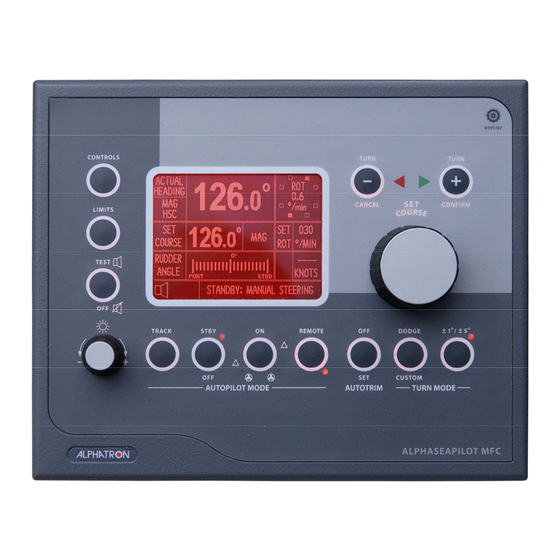
ALPHASEAPILOT MFC FIG 2 – ALPHASEAPILOT MFC Control Panel Layout The Autopilot Standby / OFF Key & Modes ( See Vessel Type p.s. 2.16 (i) OFF All Autopilot functions are inoperative (No display data or keypad LEDs activated) (ii) STANDBY Control Unit Display operational. -
Page 27: The Autopilot On Key Modes (Rudder/Thruster)
Autopilot controls (Rudder, Yaw, Counter Rudder etc.) to achieve optimum steering performance. Alternatively, the ALPHASEAPILOT MFC can function as an Adaptive Autopilot where the control parameters are automatically adjusted as a function of Speed and Draft input data which, typically, requires little or no manual adjustment beyond initial installation and Sea Trials. -
Page 28: The Controls Menu
9 and a 3:1 ratio exists between minimum and maximum settings. The factory default setting (accessible via the Set Up Menu) initially provides a Rudder Control range of 0.5 to 1.5 of Rudder per degree course error. Operating manual ALPHASEAPILOT MFC Issue 1.1 Page 28 of 84... -
Page 29: Iii) Yaw Control
Use the “CONTROLS” key to enter the Controls Menu Use the “CONTROLS” key again to select “COUNTR” box followed by flashing value “1-9” Use the rotary (+/-) illum. control to set value “1-9” as required. Operating manual ALPHASEAPILOT MFC Issue 1.1 Page 29 of 84... -
Page 30: V) Autothrust
Speed input although it must be noted that Speed through the water (STW) is essential for Speed Adaptive Autopilot operation. NO STW DATA = NO SPEED ADAPTIVE AUTOPILOT OPERATION. Operating manual ALPHASEAPILOT MFC Issue 1.1 Page 30 of 84... -
Page 31: The Rotary (+/-) Illumination Control
When any of the three Autopilot Menus have been entered (Set Up Menu, Controls Menu or Limits Menu) the parameter highlighted by the cursor is adjusted using the rotary (+/-) illumination control which, in this mode, does not alter control panel/display illumination levels. Operating manual ALPHASEAPILOT MFC Issue 1.1 Page 31 of 84... -
Page 32: The Limits Menu
Rotate the Autopilot Set Course Control to move the cursor to parameter number 35 (OHA DELAY). Use the rotary (+/-) illum. control to set 10-60 SECs as required. Operating manual ALPHASEAPILOT MFC Issue 1.1 Page 32 of 84... -
Page 33: Iii) Course Comparator Alarm
Use the “LIMITS” key to enter the Limits Menu. Use the “LIMITS” key again to select “C.COMP” box followed by flashing current value (4° to 16°). Use the rotary (+/-) illum. control to set the required value. Operating manual ALPHASEAPILOT MFC Issue 1.1 Page 33 of 84... -
Page 34: Iv) Watch Alarm
Turn value stored in the Set Up Menu – can be set (or changed) via the LIMITS Menu. NB. If ROT has not been selected in the CONTROLS Menu (i.e. RAD Turn Type selected) the ROT setting in the LIMITS Menu will not respond to cursor selection/adjustment. Operating manual ALPHASEAPILOT MFC Issue 1.1 Page 34 of 84... -
Page 35: Vi) Radius Of Turn (Rad) Calibration
Use the “LIMITS” key to enter the Limits Menu. Use the “LIMITS” key again to select “RAD:nm” box followed by flashing current value (0.1 to 9.9). Use the rotary (+/-) illum. control to set “RAD:nm” value required. Operating manual ALPHASEAPILOT MFC Issue 1.1 Page 35 of 84... -
Page 36: Vii) Dodge Angle Calibration
Use the “LIMITS” key to enter the Limits Menu. Use the “LIMITS” key again to select “CUSTOM” box followed by flashing current value (5° to 180°). Use the rotary (+/-) illum. control to set “CUSTOM” value required. Operating manual ALPHASEAPILOT MFC Issue 1.1 Page 36 of 84... -
Page 37: The Autotrim Key (Automatic Permanent Helm)
“TEST/OFF” key. This is followed by sequential illumination of all nine keypad corner LED lights accompanied in each case by an audible bleep and a 10 bleep at test end. Operating manual ALPHASEAPILOT MFC Issue 1.1 Page 37 of 84... -
Page 38: The Track Key
The “REMOTE” key condition described above is applicable to all ALPHASEAPILOT MFC Autopilot systems employing a single ALPHASEAPILOT MFC Control Unit but, in systems employing two or three (maximum) Control Units, only one of these units will be the “Master” and the others will only gain access to the Autopilot system when the “Master”... -
Page 39: The Turn Mode Keys
NEXT COURSE key confirmed by flashing red corner LED and display change to show NEXT XXX. b) Rotate the COURSE SET control until the new course required is shown in the NEXT box on the display flashing NEXT XXX. Operating manual ALPHASEAPILOT MFC Issue 1.1 Page 39 of 84... -
Page 40: Iii) The +/-1° / +/-5° Key
To Turn to Stbd – press the “TURN +” key To Turn to Port – press the “TURN –“ key (The actual value of course change ordered will be shown in the SET COURSE area of the display). Operating manual ALPHASEAPILOT MFC Issue 1.1 Page 40 of 84... -
Page 41: The Rotary Set Course Control
A NEW COURSE TIMEOUT PERIOD programmable between the limits 20 to 60 seconds is available via access to the SET UP Menu. Operating manual ALPHASEAPILOT MFC Issue 1.1 Page 41 of 84... - Page 42 (anticlockwise) or Stbd (clockwise) as required and confirmed by the SET COURSE or NEW COURSE display box. (ii) If the New Course alarm is activated, use the “CANCEL” or “CONFIRM” keys to abort or execute the turn as required. Operating manual ALPHASEAPILOT MFC Issue 1.1 Page 42 of 84...
-
Page 43: The Cancel & Confirm Keys
To Turn to STBD – press the “TURN +” key. To Turn to Port – press the “TURN –“ key. (The actual value of course change ordered will be shown in the SET COURSE area of the display). Operating manual ALPHASEAPILOT MFC Issue 1.1 Page 43 of 84... -
Page 44: The Control Unit Start Up Display (Splash Screen)
2.14 The Control Unit Start Up Display ( Splash Screen When the ALPHASEAPILOT MFC Autopilot is powered up (“OFF/STBY” key) the Control Unit start up display (or splash screen) provides various important aspects of information relevant to the software and Set Up standards of the system. -
Page 45: The Control Unit Operational Display
The Control Unit display also provides reference to the comprehensive installation “Set Up” Menu (Installation and Technical Manual Section 3) and is accessed via simultaneous 5 second operation of the CANCEL and CONFIRM keys. Operating manual ALPHASEAPILOT MFC Issue 1.1 Page 45 of 84... -
Page 46: Sea Trials And Autopilot Type Selection
ALPHASEAPILOT MFC 2.16 Sea Trials and Autopilot Type Selection It is essential to note that the ALPHASEAPILOT MFC Autopilot has dual Type Approvals covering conventional displacement vessels up to typically 30 knots and High Speed Craft for speeds up to 70 knots. -
Page 47: Mag/True Heading Assessment
Autopilot engagement, any rudder offset angle (Trim or Permanent Helm) manually determined for this purpose will be sampled and held by the Autopilot and the vessel will continue to steer dead ahead). Operating manual ALPHASEAPILOT MFC Issue 1.1 Page 47 of 84... -
Page 48: Initial Course Keeping Performance
Yaw: - Typical tight ‘S’ Typical stretched ‘S’ characteristic characteristic of of Understeer Oversteer Action required: - Action required: - Increase Rudder Reduce Rudder Control Setting. Control Setting. (Anticlockwise) (Clockwise) Operating manual ALPHASEAPILOT MFC Issue 1.1 Page 48 of 84... -
Page 49: Optimising The Rudder Control Setting
Fast planing/semi planing vessels (HSC) 0.33° to 1° per degree Deep sea fishing vessels etc. 0.5° to 1.5° per degree Heavy displacement ocean going vessels 1.0° to 3.0° per degree Operating manual ALPHASEAPILOT MFC Issue 1.1 Page 49 of 84... -
Page 50: Loop Gain Calibration
Autopilot switched from STANDBY to ON Autotrim function operational. (ii) Autotrim key to OFF Immediately cancels any (5 second press) permanent helm rudder offset angle and disables the Autotrim function. Operating manual ALPHASEAPILOT MFC Issue 1.1 Page 50 of 84... - Page 51 20° (i.e. 20° to Port or Stbd of the current course). This automatic trip point is reprogrammable via the Set Up Menu and can be lowered in one-degree steps from ±180° to ±20°. Operating manual ALPHASEAPILOT MFC Issue 1.1 Page 51 of 84...
- Page 52 (iii) Rotate the illum. control (+/-) to to set the required time constant. (iv) Exit the Set Up Menu (simultaneous 5 sec operation of the CANCEL & CONFIRM keys). Operating manual ALPHASEAPILOT MFC Issue 1.1 Page 52 of 84...
-
Page 53: The Counter Rudder Control Setting
Rotate the illum. control (+/-) to increase or decrease the flashing “COUNTR” No. (1 to 9) as required. (The flashing counter value will timeout after a period of 30 seconds and the display will automatically revert to the standard operational mode). Operating manual ALPHASEAPILOT MFC Issue 1.1 Page 53 of 84... -
Page 54: Optimising The Yaw Control Setting
Rotate the illum. control (+/-) to increase or decrease the setting as required. (iii) Timeout and retention of new setting will occur automatically when the display will revert to the standard operating mode. Operating manual ALPHASEAPILOT MFC Issue 1.1 Page 54 of 84... -
Page 55: Stw Speed Data Input (Speed Through The Water)
Draft data is restored or the audible alarm is muted by 5 second operation of the TEST/OFF key. NB. If the alarm is muted in this manner – ALL audible alarms will be muted. Operating manual ALPHASEAPILOT MFC Issue 1.1 Page 55 of 84... -
Page 56: Calibration Of Adaptive Steering Performance Vs Speed
CAL3 respectively) to capture and store the related Rudder/Speed data. Enter controls menu by pressing CONTROLS key and ensure ADAPT value box is flashing. Simultaneous 5 second CONTROLS and LIMITS key operation to exit the calibration mode. Operating manual ALPHASEAPILOT MFC Issue 1.1 Page 56 of 84... -
Page 57: Iii) To Calibrate Adaptive Autopilot Steering Vs Speed
The Autopilot system is now calibrated and set to work in the Adaptive mode but it should be noted that entry to the ‘CONTROLS’ menu (CONTROLS key operation) will permit manual intervention/update of any current control parameters (RUDDER, COUNTER, YAW etc.) at any time if required. Operating manual ALPHASEAPILOT MFC Issue 1.1 Page 57 of 84... -
Page 58: Calibration Of Adaptive Steering Performance Vs Draft
The Autopilot system is now calibrated and set to operate in the Adaptive mode taking account of Speed and Laden state (draft) input data. FIG 2.29 (ii) Override Cal FIG 2.29 (iii) Speed Cal Operating manual ALPHASEAPILOT MFC Issue 1.1 Page 58 of 84... -
Page 59: Setting The Rudder Limit Control
If Track Steering mode is operational using the HTC sentence, it is possible for the Track Control system to override the Rudder limit value set within the Autopilot LIMITS Menu. Operating manual ALPHASEAPILOT MFC Issue 1.1 Page 59 of 84... -
Page 60: Setting Rate Of Turn Control
Use the “LIMITS” key to enter the Limits Menu. (ii) Use the “LIMITS” key again to select “ROT°/S” box followed by flashing current value. (iii) Use the rotary (+/-) illum. control to set “ROT” value required. Operating manual ALPHASEAPILOT MFC Issue 1.1 Page 60 of 84... -
Page 61: Setting Maximum Safe Rate Of Turn
In the event that maximum Safe Rate of Turn is reached during Autopilot Control, the Autopilot system will limit to prevent further increase and the Control Unit ACTUAL ROT display will show actual ROT value alternating with MAX. Operating manual ALPHASEAPILOT MFC Issue 1.1 Page 61 of 84... -
Page 62: Setting Radius Of Turn
“NO SOG DATA” in bottom left alarm box of Control Unit display accompanied by audible bleep. SOG too slow = flashing “SPEED LOW” in bottom left alarm box of Control Unit display accompanied by audible alarm. Operating manual ALPHASEAPILOT MFC Issue 1.1 Page 62 of 84... -
Page 63: Optimising The Off Heading & Course Comparator (Cca) Alarms
Use the “LIMITS” key to enter the Limits Menu. Use the “LIMITS” key again to select “O.H.A.” box followed by flashing current value (2° to 30° or OFF). Use the rotary (+/-) illum. control to set as required. Operating manual ALPHASEAPILOT MFC Issue 1.1 Page 63 of 84... - Page 64 Use the “LIMITS” key to enter the Limits Menu. Use the “LIMITS” key again to select “C.COMP” box followed by flashing current value (4° to 16°). Use the rotary (+/-) illum. control to set the required value. Operating manual ALPHASEAPILOT MFC Issue 1.1 Page 64 of 84...
-
Page 65: Setting And Confirming New Autopilot Courses
A second CONFIRM key operation is therefore required after ordering direction of the turn and, if the U TURN Mode is selected without follow up action, the mode will automatically be deselected after a timeout period of 30 seconds. (Section 2.11 refers). Operating manual ALPHASEAPILOT MFC Issue 1.1 Page 65 of 84... -
Page 66: Setting The Watch Alarm Period
Use the “LIMITS” key again to select “WATCH” box followed by flashing current value (OFF or 3 to 12). Use the rotary (+/-) illum. control to set the required condition. Operating manual ALPHASEAPILOT MFC Issue 1.1 Page 66 of 84... -
Page 67: The Track Function
“Heading to Steer” data received from a proprietary Track Control System. NB. The ALPHASEAPILOT MFC is a “Wheelmarked” Autopilot (IMO A342(ix) as amended by MSC 64/67 Annex 3) in addition to HSC Certification (ISO 16329) with an approved Track steering facility provided the latter is used in conjunction with a Type Approved Track Control System compliant with IEC 60625. -
Page 68: I) Track Mode Display And Status Information
15 seconds beyond which the alarm will sound again until effective action is taken (Confirm key operated or Track key operated to disable Track Mode Steering). Operating manual ALPHASEAPILOT MFC Issue 1.1 Page 68 of 84... -
Page 69: Ii) Track Mode Alarms
Track function is simply engaged by operation of the TRACK key and will be confirmed by the Control Unit display and illumination of the red corner LED in the TRACK key. Operating manual ALPHASEAPILOT MFC Issue 1.1 Page 69 of 84... -
Page 70: Manual And Auto Deviation Correction
“bleeps” will be heard confirming that Heading data comparisons are being made and stored until, finally, the display shows SAVE?. (g) Press the AUTOTRIM key to save the data which will be confirmed by the message END. Operating manual ALPHASEAPILOT MFC Issue 1.1 Page 70 of 84... -
Page 71: Ii) Manual Deviation Correction Procedure
(c) Press and hold the AUTOTRIM key confirmed by a display countdown of 5 secs, 4 secs etc. until RESET is shown. (d) Release the AUTOTRIM key to complete clear down. Operating manual ALPHASEAPILOT MFC Issue 1.1 Page 71 of 84... -
Page 72: Alphaseapilot Mfc Second Station Control Units
ALPHASEAPILOT MFC 2.40 ALPHASEAPILOT MFC Second Station Control Units All ALPHASEAPILOT MFC Autopilot system Control Units are identical and may be used in Master/Slave configurations as required up to a maximum of 3 Control Units per system. NB. Where one than one Control Unit is involved it is important to note that each must have its own dedicated address (No.1, No.2 or No.3). -
Page 73: Nt920 Nfu Power Steering - Refer To Section 1.21
This is conventional Follow Up Power Steer operation and can be selected via the Autopilot SET UP Menu (Parameter No.62 set to NORM). Application notes in Section TM3 of the Installation and Technical Manual. Operating manual ALPHASEAPILOT MFC Issue 1.1 Page 73 of 84... -
Page 74: Ii) Non Latched Jog Lever (Non Follow Up) Override Control
Autopilot SET UP Menu (Parameter Nos.62 - set to HSC LATCH - and 64). Application notes in Section TM3 of the Installation and Technical Manual. Operating manual ALPHASEAPILOT MFC Issue 1.1 Page 74 of 84... -
Page 75: Iv) To Select The Isolated Input Steering Mode
(NORM/HSC LATCH/JOG). c) Use the rotary (+/-) illum. control to select as required. 2.43 (v) To Calibrate Isolated Input Steering Modes against Speed:- Refer to Adaptive Mode Calibration Section 2.29. Operating manual ALPHASEAPILOT MFC Issue 1.1 Page 75 of 84... -
Page 76: Display Messages, Alarms And Status Indicators
These are brought to the attention of the watch by audible and visual means as follows: - Displays at Power Up (Self Test) Failure Messages at Power Up (Self Test Failure) Operational Display Messages Alarm Display Messages Operational Status LED’s Operating manual ALPHASEAPILOT MFC Issue 1.1 Page 76 of 84... -
Page 77: Display At Power Up
ALPHASEAPILOT MFC Display at Power Up When the ALPHASEAPILOT MFC Autopilot is powered up (“OFF/STBY” key) the Control Unit start up display (or splash screen) provides various important aspects of information relevant to the software and Set Up standards of the system. -
Page 78: Operational Display Messages
STEERING – 2 Station/Track Mode/Thruster (xiv) REM AUTOTRACK STEERING – 2 Station – Track Mode with Rudder & Thruster (xv) TRACK STBY MANUAL STEERING– Track system forcing Autopilot to STANDBY Mode Operating manual ALPHASEAPILOT MFC Issue 1.1 Page 78 of 84... - Page 79 Autopilot courses are ordered via the rotary Set Course Control or the Turn Mode keys. New Autopilot course display details are shown in Section 2.36. Track Mode display details are shown in Section 2.38 (i). Operating manual ALPHASEAPILOT MFC Issue 1.1 Page 79 of 84...
-
Page 80: Alarm Display Messages
- Analogue voltage regulation defect +2.5V FAIL - Analogue voltage regulation defect NO ORIDE CAL – Override power steer control requested but not calibrated DRAFT IN FAIL – 4-20mA Draft input signal fail Operating manual ALPHASEAPILOT MFC Issue 1.1 Page 80 of 84... -
Page 81: Iii) Speed Data Alarms
– Watch alarm timeout period completed RUDDER LIMIT – Specified rudder angle reached Operational Status LED’s There are a total of 11 LED’s on the ALPHASEAPILOT MFC Control Unit panel:- (i) O STBY – Red corner LED illuminated confirms STANDBY Mode (ii) O ON... -
Page 82: Dimensions Alphaseapilot Mfc
ALPHASEAPILOT MFC Dimensions ALPHASEAPILOT MFC Operating manual ALPHASEAPILOT MFC Issue 1.1 Page 82 of 84... -
Page 83: Connectiondiagram Alphaseapilot Mfc
ALPHASEAPILOT MFC Connectiondiagram ALPHASEAPILOT MFC Operating manual ALPHASEAPILOT MFC Issue 1.1 Page 83 of 84... -
Page 84: Alphatron Agents (Authorized)
UNITED ARAB EMIRATES Elcome International L.L.C. Al Jadaf Dockyard – DY159 P.O. Box 1788 DUBAI UNITED ARAB EMIRATES Tel. + 971 4 4049100 Fax. + 971 4 049200 Internet: www.elcome.ae E-mail: info@elcome.ae Operating manual ALPHASEAPILOT MFC Issue 1.1 Page 84 of 84...
Need help?
Do you have a question about the ALPHASEAPILOT MFC and is the answer not in the manual?
Questions and answers