
Related Manuals for Bogobit Bremsmodul Classic Series

Summary of Contents for Bogobit Bremsmodul Classic Series
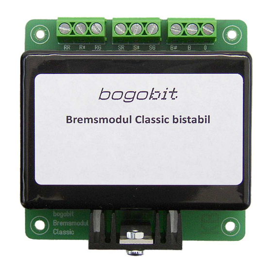
- Page 1 Bogobit Bremsmodul Classic – Manual bogobit Bremsmodul Classic · 2016-08-01 page 1 / 12...
-
Page 2: Intended Use
All brand, product and company names used herein may be trademarks of their respective owners. 2 Intended Use The Bogobit Bremsmodul Classic is a brake module for digitally controlled model railways. The mo- dule generates a “brake voltage”. This lets locos brake smoothly if they are equipped with a suita- ble decoder. -
Page 3: Electrical Safety
4 Function of the bogobit Bremsmodul 4.1 General Function The Bogobit Bremsmodul Classic is a brake module for digitally controlled model railways. The mo- dule generates a “brake voltage”. This brake voltage, when applied to the track, lets locos brake smoothly if they are equipped with a suitable decoder. - Page 4 4.2 Hardware versions of the brake module The Bogobit Bremsmodul Classic is available in different versions. The differ in the electronic com- ponents on the module, in their function, and in their connections. The following version are avail- able: 1.
-
Page 5: Connection And Operation
Also consider the instructions related to heat generation in chapter 3.3. 5.3 Connections – Version “Bistabil” This section describes the version “Bistabil” of the Bogobit Bremsmodul. Section 5.4 describes the version “Monostabil”, and section 5.5 the version “Bremsgenerator”. 5.3.1 Wiring Terminals... - Page 6 Such a stop section is realised by another track section that is wired via the terminals "S∗" and "SG" and connected with "B". Graphical wiring diagrams can be found in a separate document [1]. bogobit Bremsmodul Classic · 2016-08-01 page 6 / 12...
- Page 7 5.4 Connections – Version “Monostabil” This section describes the version “Monostabil” of the Bogobit Bremsmodul. The version “Monostabil” uses a monostable (non-latching) relay. This version is suitable if a on-off-voltage is available. This can be provided, e. g., by the switch con- tact built into the solenoid drive of a light or semaphore signal (originally intended to switch off track voltage).
- Page 8 Such a stop section is realised by another track section that is wired via the terminals "S∗" and "SG" and connected with "B". Graphical wiring diagrams can be found in a separate document [1]. bogobit Bremsmodul Classic · 2016-08-01 page 8 / 12...
- Page 9 5.5 Connections – Version “Bremsgenerator” This section describes the version “Bremsgenerator” of the Bogobit Bremsmodul. 5.5.1 Wiring terminals All external connections of the brake module are labelled on the board and explained in the table below: Label Function digital track voltage input center stud track: B is the red wire to the center studs, 0 is the brown wire to the rails ground.
-
Page 10: Maintenance And Care
DC voltage when in „brake“ state. The max. allowed current is 2 A. The maximum relay switching capacity is 2 A current and 30 V DC or 25 V AC voltage. bogobit Bremsmodul Classic · 2016-08-01 page 10 / 12... -
Page 11: Control Input
This version has no control input. 8 Further Notes 8.1 CE Marking The following declaration only applies to products that are manufactured by Bogobit. The product Bogobit Bremsmodul Classic complies with the following directives: EU Directive 2014/30/EU on electromagnetic compatibility •... -
Page 12: Address Of Manufacturer
Germany E-Mail: anfrage@bogobit.de 9 References The following documents have further information on putting into service: Wiring schemes (German: Anschlussbeispiele) Bogobit Bremsmodul Classic, see: http://bogobit.de/bremsmodul/classic chapter „Weiterführende Informationen“ Website on recommended decoder settings: http://bogobit.de/bremsmodul/decodereinstellung The following documents have information on building a kit. Download from http://bogobit.de/bremsmodul/classic...
Need help?
Do you have a question about the Bremsmodul Classic Series and is the answer not in the manual?
Questions and answers