Table of Contents
Advertisement
Model AM2
Installation Guide
NOTE:
This product is intended for installation by a professional installer only!
Any attempt to install this product by any person other than a trained professional
may result in severe damage to a vehicle's electrical system and components.
© 2007 Directed Electronics, Vista, CA
N2102A 2007-06
Advertisement
Table of Contents

Related Manuals for Automate AM2


Summary of Contents for Automate AM2
-
Page 1: Installation Guide
Model AM2 Installation Guide NOTE: This product is intended for installation by a professional installer only! Any attempt to install this product by any person other than a trained professional may result in severe damage to a vehicle’s electrical system and components. - Page 2 Code Hopping , Doubleguard , ESP , FailSafe , Ghost Switch , Learn Routine™, Nite-Lite ® ® ® ® ® ® Nuisance Prevention Circuitry, NPC , Revenger , Silent Mode™, Soft Chirp , Stinger®, Valet ® ® ® ® ® Vehicle Recovery System , VRS , and Warn Away...
- Page 3 Table of Contents p p r r i i m m a a r r y y h h a a r r n n e e s s s s ( ( H H 1 1 ) ) , , 1 1 2 2 - - p p i i n n c c o o n n n n e e c c t t o o r r ..................4 4 P P e e r r i i p p h h e e r r a a l l P P l l u u g g - - I I n n H H a a r r n n e e s s s s e e s s .
- Page 4 primary harness (H1), 12-pin connector (+) 12V CONSTANT POWER INPUT H1/1 BLUE (-) 200 mA SECOND UNLOCK OUTPUT H1/2 BLACK/WHITE-1 DOMELIGHT INPUT SUPERVISION/AUX CHNL 2 RELAY #87 H1/3 BLACK/WHITE DOMELIGHT OUTPUT SUPERVISION/AUX CHNL 2 RELAY #30 H1/4 GREEN/BLACK LOCK #30 COMMON OUTPUT H1/5 WHITE/BLACK LOCK #87A NORMALLY CLOSED...
- Page 5 H1/3 BLACK/WHITE-1 D D o o m m e e l l i i g g h h t t S S u u p p e e r r v v i i s s i i o o n n /Aux Channel 2 Input (pin 87) This wire determines what the output polarity of H1/4 will be.
- Page 6 H1/11 BLACK (-) Chassis Ground Connection Connect this wire to a clean, paint-free sheet metal location (driver kick panel) using a factory bolt that DOES NOT have any vehicle component grounds attached to it. A screw should only be used when in conjunction with a two-sided lock washer.
- Page 7 H1/14 WHITE/BLUE (-) Channel 3 Output This wire provides a (-) 200 mA output whenever the transmitter code controlling Channel 3 is received. This output will continue as long as that transmission is received. Use for options such as Directed’s 561T Valet Start system, 529T or 530T power window controllers, etc.
- Page 8 H1/16 ORANGE (-) 500mA Ground-When Armed Output This wire supplies a (-) 500mA ground as long as the system is armed. This output ceases as soon as the system is disarmed. Note: If using the H1/16 Orange wire to activate an add-on accessory such as window automation, pager or voice module a 1-Amp diode must be installed to ensure proper operation.
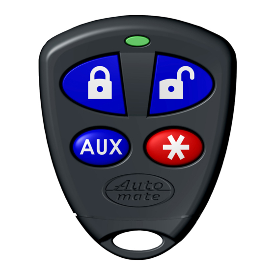
- Page 9 Peripheral Plug-In Harnesses Integrated LED/Valet ® ® Switch, 2-Pin BLUE Plug The integrated LED/Valet switch should be accessible from the driver’s seat. It plugs into the BLUE ® port on the side of the unit. Consider how the button will be used before choosing a mounting location.
- Page 10 T T r r a a n n s s m m i i t t . . The transmitter is used to select the desired setting. As shipped, the unit is configured to the LED ON/1 chirp settings. These are the default settings.
- Page 11 System Features Menus Feature One-chirp/LED ON Setting Two-chirp/LED OFF Setting Number (chirp# in ( ) for multiple options) Active arming Passive(2)/Auto rearm setting(3) Horn honk ON OFF(2)/OEM style(3) Horn output duration 50ms 20ms(2)/30ms(3)/40ms(4) Ignition lock OFF Ignition lock ON Ignition unlock OFF Ignition unlock ON Active locking Passive locking...
- Page 12 1 A A C C T T I I V V E E /PASSIVE/AUTO REARM ARMING: When active arming is selected, the system will only arm when the transmitter is used. When set to passive, the system will arm automatically 30 seconds after the ignition is turned off.
- Page 13 11 SECURITY FEATURES: When selected O O F F F F , the (-) ground-when-armed and ignition sense trigger will not be active upon locking the vehicle. When selected ON, (-) ground-when-armed output will be active and can be used to operate a starter kill. The unit will also trigger a panic sequence if the ignition is turned on before unlocking/disarming the system.
- Page 14 C C h h o o o o s s e e . . Within 10 seconds, press and release the Valet/program switch the number of times corresponding to the desired channel listed below. Once you have selected the channel, press the switch once more and HOLD it.
- Page 15 Transmitter Configurations The transmitters can be programmed with the standard or single button arm/disarm configurations by using the Auto Learn functions in the Transmitter/Receiver Learn Routine. Standard Configuration A remote that uses the standard configuration operates similarly to many factory keyless entry remotes.
- Page 16 Programming Master Dealer Remotes Follow the program instructions above and use the Directed part number 465D(master dealer remote). The only programming channels in master dealer mode are channel 1 and 8. CHANNEL NUMER FUNCTION Auto Learn Delete all transmitters Rapid Resume Logic Rapid Resume Logic ensures that the when the system is powered up it will return to the same state it was in when power is disconnected.
- Page 17 Wiring Quick Reference Guide 2007 © Directed Electronics...
Need help?
Do you have a question about the AM2 and is the answer not in the manual?
Questions and answers