Table of Contents
Advertisement
Advertisement
Table of Contents

Related Manuals for TMC STACIS 2100


Summary of Contents for TMC STACIS 2100
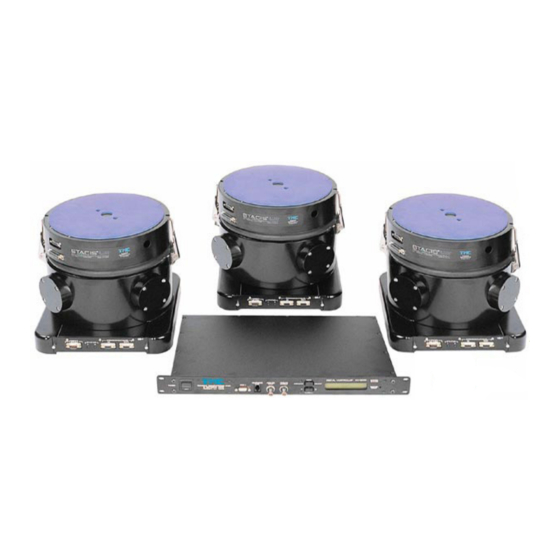
- Page 1 ® ® ® ® STACIS 2100 Piezoelectric Active Vibration Isolation System INSTALLATION & OPERATION MANUAL TECHNICAL MANUFACTURING CORPORATION 15 CENTENNIAL DRIVE PEABODY, MA 01960 Tel: 978-532-6330 Fax: 978-531-8682 Website: www.techmfg.com Document P/N 96-28765-01 Rev. N...
-
Page 2: Table Of Contents
® STACIS 2100 Piezoelectric Isolation System - Installation & Operation Manual P/N 96-28765-01 TABLE OF CONTENTS: ........................1 Principle of Operation .................... 5 General Information....................6 Introduction ............................. 6 Product Selection..........................6 General Specifications........................7 2.3.1 Performance ..........................7 2.3.2 Physical Dimensions ....................... - Page 3 System Status LED and Alarm Relay................... 36 The DI/O Interface ........................36 Connector Pinouts ........................37 Appendix B: Using TMC Analyzer to Collect and Upload Data......42 List of Tables & Figures ® Figure 1: Vertical and Horizontal Transmissibility for STACIS 2100............
- Page 4 Symbols Used in this Manual Symbol Purpose Symbol Purpose Warning / Caution Important Information or Notes Reminder Warning: No user-serviceable parts inside isolators or controller. If the system fails to perform as specified, please contact TMC for repair or service. Page 4 of 43...
-
Page 5: Principle Of Operation
Figure 1: Vertical and Horizontal Transmissibility for STACIS 2100 TMC’s DC-2000 Digital Controller is used to implement sophisticated non-linear feedback algorithms. These ensure the isolation system performs well in extreme circumstances such as deep saturation and The horizontal and vertical transmissibility was measured on a special shaker table with micron-level input. The isolated mass was granite. -
Page 6: General Information
Isolator and provides communications and diagnostics. Product Selection ® TMC can provide on-site surveys to determine the suitability of STACIS for a particular installation. The survey includes: Vibration measurements to determine if the proposed site’s floor noise is within the dynamic •... -
Page 7: General Specifications
® STACIS 2100 Piezoelectric Isolation System - Installation & Operation Manual P/N 96-28765-01 General Specifications 2.3.1 Performance Active Degrees of Freedom (system of 3+ isolators)...................6 Active Bandwidth........................0.6 to 150 Hz Transmissibility at Resonance ....................... <1.1 Isolation above 2Hz..........................>90% Settling Time (10 lb. -
Page 8: Terminology Defined
® STACIS 2100 Piezoelectric Isolation System - Installation & Operation Manual P/N 96-28765-01 2.3.7 Terminology Defined ® Terms specific to the STACIS isolation system and its operation are listed below for your convenience. Table 2: Terminology Used in the Manual Term: Meaning: ®... -
Page 9: Installation
The carrier and TMC should be notified immediately, and a claim should be filed with the carrier. The carrier is responsible for all shipping damages and all claims for damages must be made against the carrier. -
Page 10: Floor Surface Requirements
Contact TMC for set-up training specific to your application. • STACIS 2100 should be installed on a concrete floor and not on a raised computer floor. If the concrete floor is flat within .02” (.5 mm) over the area of the isolator and level so that each isolator location is at the same height within .12”... -
Page 11: Installation Spacer
480 µ” (12 µm) of displacement, one or more channels of the STACIS isolators may overload and isolation may be briefly lost. If it is known, or suspected, that the floor exceeds the maximum displacement, consult with TMC. A maximum floor displacement of 400 µ” (10 µm) is recommended to provide a... -
Page 12: Payload/Stacis Interface
2.2, or through information supplied to TMC. If the payload has more than four points of support, or if the support points do not completely cover the top surface of each Isolator, an interface plate will be needed. Some suggested configurations are shown in Figure 5. - Page 13 If the system will not be used as a shaker, the isolators may be placed in any • location and orientation that provides the best loading. Contact TMC for a setup drawing specific to your application. Page 13 of 43...
-
Page 14: Detailed Mechanical Installation Steps (Pre-Power Up)
® STACIS 2100 Piezoelectric Isolation System - Installation & Operation Manual P/N 96-28765-01 Detailed Mechanical Installation Steps (Pre-Power Up) If risers or baseplates will be used, they must be installed with grout a minimum of 12 • hours prior to operating the STACIS system. See “Pre-Installation Manual and Checklist”. -
Page 15: Initial Power Up And Load Adjustment
® STACIS 2100 Piezoelectric Isolation System - Installation & Operation Manual P/N 96-28765-01 If using wooden blocks, place a bottle jack between two isolators, centered under one end of the platform, • raise the platform slightly, just enough to remove the spacer blocks, •... - Page 16 ® STACIS 2100 Piezoelectric Isolation System - Installation & Operation Manual P/N 96-28765-01 The sensor reading is not related to the overall height of the isolator. • Adjusting the wedgemount in one isolator will affect the displayed value by altering the •...
-
Page 17: Table 4: Load Sensor Calibration
• isolator is loaded outside of this range, follow the instructions in the following section to re-distribute the load. If all isolators are out of this range, please contact TMC. 15) Isolator Load Re-Distribution Using the Internal Wedgemount For a 3-isolator system, if the isolators are not properly loaded, their installation location must be changed until each isolator is within the proper load range specified above. - Page 18 ® STACIS 2100 Piezoelectric Isolation System - Installation & Operation Manual P/N 96-28765-01 When performing the load adjustment procedure, the cable to the HVA connector (bottom of the Isolator) must be disconnected. The following procedure applies only to a 4-isolator system. A tool is provided for adjusting the loading of the isolators using the wedgemounts.
-
Page 19: System Initialization
® STACIS 2100 Piezoelectric Isolation System - Installation & Operation Manual P/N 96-28765-01 Ensure the difference in the displacement readings is kept to a minimum. For • example, on a symmetric payload supported by 4 isolators, the isolators along one diagonal should not be loaded more than those on the opposite diagonal. - Page 20 2. HVAs are not properly connected to the isolators. 3. Cables are not properly connected. 4. System is simply not functioning correctly. If this is the case, contact TMC Service. Report all “Not Optimized” messages to TMC. Page 20 of 43...
- Page 21 OFF and then turn it back ON after approximately 10 secs to repeat the power up sequence. If system still does not function correctly, contact TMC service. If at any time during operation the system becomes unstable, proceed to section 6.4 for instructions on control loop gains adjustment using the menu...
-
Page 22: Menu Driven Functions
(such as COM port function). Menu Tree: On power up the controller LCD displays a message like “TMC STACIS 2100” “pn 95-28576-01 r #”; pressing any one of the menu key leads to the first main menu option; pressing PREVIOUS repeatedly from any menu tree level returns to the default display. - Page 23 ® STACIS 2100 Piezoelectric Isolation System - Installation & Operation Manual P/N 96-28765-01 TMC STACIS 2100 pn 95-28756-01 R.## Menu: PREVIOUS -/+ Selects Function Monitor X/Y/Z Signal Any Key Menu: SELECT Cursor: (+) Cursor: (-) Menu: PREVIOUS Menu: PREVIOUS -/+ Selects Function...
-
Page 24: Figure 13: Detailed Menu Structure For Stacis ® 2100
® STACIS 2100 Piezoelectric Isolation System - Installation & Operation Manual P/N 96-28765-01 TMC STACIS 2100 pn 95-28756-01 r # -/+ Selects Function -/+ Selects Axis Monitor X/Y/Z Signal BNC Output: 1Z axis -/+ Selects Function: Iso1:2.6 Iso2:2.8mm Monitor Load Sensors Iso3:2.7 Iso4:2.4mm... - Page 25 ® STACIS 2100 Piezoelectric Isolation System - Installation & Operation Manual P/N 96-28765-01 -/+ Selects Function -/+ → LF/HF SELECT → Set -/+ → Disable/Enable LF/HF Alarms LF Alarm LF Alarms Enabled -/+→LF/HF SELECT→Set -/+ → Disable/Enable HF Alarm HF Alarms Enabled -/+ Selects Function -/+ →...
-
Page 26: Description Of Menu Tree Functions
If saturation occurs, the resultant payload motion will no longer be proportional to the input. TMC recommends that a reference sensor (such as an accelerometer) is always used to confirm that the payload motion is correct. -
Page 27: Adjust X/Y/Z Gains - Gain Adjustment
STACIS 2100 Piezoelectric Isolation System - Installation & Operation Manual P/N 96-28765-01 system) using the TMC PC based application TMC Analyzer . See Appendix C for detailed instructions on running the analyzer software . 5.3.5 Adjust X/Y/Z Gains - Gain Adjustment All control gains of the STACIS®... -
Page 28: Sat./Osc. (Saturation/Oscillation) Control
(periods of high seismic noise or large payload disturbances). TMC strongly recommends that these functions remain enabled during system operation. They may be disabled only for diagnostic purposes and reset to “ enabled ” once the diagnostic is completed. -
Page 29: Lf/Hf Alarms
® STACIS 2100 Piezoelectric Isolation System - Installation & Operation Manual P/N 96-28765-01 LF/HF Alarms 5.3.8 This is the menu option for enabling or disabling the alarms for Oscillation Control and Saturation Control. ® These two features monitor the operation of the STACIS system for oscillation and saturation, respectively (see Oscillation Control and Saturation Control sections above). -
Page 30: Select Number Of Isolators
® STACIS system, i.e. isolators and controller, the correct number of isolators is pre-configured at TMC before to shipment. This function makes it possible to update the number of isolators in the event of a change in the installation, e.g. an isolator is added or removed due to changes in the weight of the payload, etc. -
Page 31: Set Powerup Test
® STACIS 2100 Piezoelectric Isolation System - Installation & Operation Manual P/N 96-28765-01 5.3.10 Set Powerup Test Menu option for enabling or disabling the automatic execution of the Power Up Self Test. The self test at power up consists of running “open loop” gain and phase measurements for each axis. If the power up self test is run in a “noisy”... -
Page 32: Downloading New Software
® STACIS 2100 Piezoelectric Isolation System - Installation & Operation Manual P/N 96-28765-01 6 Downloading New Software: New system operating software can be downloaded by connecting the controller to a computer via the serial ports (COM1 or COM2). The software package shipped with the system includes a program called SerialLoader.exe to facilitate the downloading process. - Page 33 ® STACIS 2100 Piezoelectric Isolation System - Installation & Operation Manual P/N 96-28765-01 7. Turn the controller power OFF, and then back ON after 10 seconds. The System Status LED on the Controller’s front panel will be “red”, and then turn “green” and start to blink. Click the OK button above or press the Enter key on the computer keyboard immediately after the status LED starts blinking “green”.
- Page 34 ® STACIS 2100 Piezoelectric Isolation System - Installation & Operation Manual P/N 96-28765-01 Failed Downloads: On rare occasions, a software download will fail the checksum and the new software will NOT be written to flash. If download fails, Manually shut the power OFF and then back ON to reboot the old version of the application software.
-
Page 35: Appendix A: Dc-2000 Controller Overview
® STACIS 2100 Piezoelectric Isolation System - Installation & Operation Manual P/N 96-28765-01 7 Appendix A: DC-2000 Controller Overview Controller Performance Specifications Analog Inputs ..............16 x16 bit / 96dB Dynamic Range, ± 10V full scale Analog Input Protection........................± 15 Volts Analog Outputs ...............16 x 14 bit / 84dB Dynamic Range, ±... -
Page 36: System Status Led And Alarm Relay
® STACIS 2100 Piezoelectric Isolation System - Installation & Operation Manual P/N 96-28765-01 Ref. # Name Description Alarm Relay, AUX Power ”Dry contact” alarm relay, Auxiliary power source; used in Interface special applications; pinout information follows. Main Analog I/O Connector, Cable connection point to isolation system using channels 0-7 Channels 0-7 as designated. -
Page 37: Connector Pinouts
The jumpers are set as shown above by default, but can be changed before shipping upon request. The jumpers are internal to the controller and must be changed at the factory, or by authorized TMC personnel only All of the LED (+) terminals are connected to a common +5 volt bus through 1.5 KOhm •... -
Page 38: Table 7: Analog Input/Output Channels 0-7 Db-37 Connector Pinout
® STACIS 2100 Piezoelectric Isolation System - Installation & Operation Manual P/N 96-28765-01 Pin # Function Pin # Function Pin # Function Pin # Function D in 7 D out 14 N. C. D out 15 +5 VDC GND. D in 8 D out 0 ‘N.C.’... - Page 39 ® STACIS 2100 Piezoelectric Isolation System - Installation & Operation Manual P/N 96-28765-01 AUX. Power Interface This connector located in the rear of the controller can be utilized as an auxiliary power source or a “dry contact” alarm relay. Table 9: AUX. Power Interface Connector Pinout: Pin # Function + 48V...
-
Page 40: Table 10: Com1& Com2 Pinouts
8 bit value of two ASCII format bytes, followed by the a carriage return ( <CR>) . If an unknown The table below lists typical command is issued, the system echoes back “Unknown Command”. serial port commands. Contact TMC for more information. Page 40 of 43... -
Page 41: Table 11: Summary Of Serial Port Commands
<CR> changes to system operating parameters. “Part Number” - sends the TMC system software part number and revision to the front <CR> panel LCD. It also echoes the P/N to the serial port if the port is used. “Print System Status”... -
Page 42: Appendix B: Using Tmc Analyzer To Collect And Upload Data
R u n P C P r o g r a m T M C A n a l y z e r C. Launch the TMC analyzer application Analyzer.exe. A screen similar to the one below will display. Step D... - Page 43 G. Click on Save Test File and then save test data for each axis as a CSV file. H. After collecting the transfer function for all axes, exit from Upload Data to PC controller LCD menu and close TMC Analyzer program. E-mail test data files to TMC for review. Page 43 of 43...
Need help?
Do you have a question about the STACIS 2100 and is the answer not in the manual?
Questions and answers