
Related Manuals for FW Murphy MLS Series


Summary of Contents for FW Murphy MLS Series
- Page 1 MLS Series Liquid Level Switches Installation and Operations Manual 00-02-0730 2019-01-15 Section 15...
- Page 2 CAUTION: MLS Series parts are not interchangeable with other FW Murphy liquid level products. Damage caused by using incorrect parts is not covered by our Limited Warranty. Please read the following information before installing. A visual inspection for damage during shipping is recommended before mounting.
-
Page 3: Table Of Contents
Pressure Vessel Installation ..................... 3 Direct Installation into the Wall of the Pressure Vessel ..........3 Installation with a Weld Collar ..................4 Installation Using FW Murphy External Float Chamber ..........4 Electrical Wiring ......................5 Testing the MLS at Routine Preventive Maintenance ............6 Test Button –... - Page 4 THIS PAGE INTENTIONALLY LEFT BLANK...
-
Page 5: Product Information
Product Information MLS Series Liquid Level Switches with 2 inch NPT and 1-1/2 inch NPT mounting are float activated to operate an electrical SPDT reed switch for alarm or shutdown of an engine or electric motor. The MLS Series connects directly into the scrubber wall and can be used with an FW Murphy weld collar or FW... -
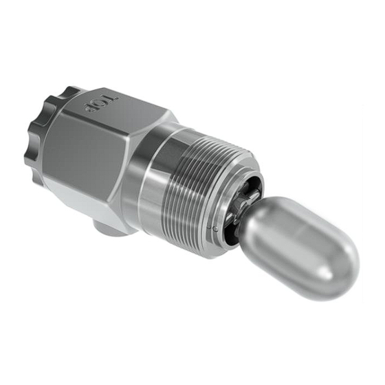
Page 6: Mls Diagram
MLS Diagram All models of the MLS Series install the same and share dimensions other than Test Button. MLS (TF) Models NOTE: Refer to Table 2 for clearances. Section 15 00-02-0730 2019-01-15 - 2 -... -
Page 7: Pressure Vessel Installation
Pressure Vessel Installation Direct Installation into the Wall of the Pressure Vessel CAUTION: Determine that the float travel is not obstructed by the coupling in the vessel wall, internal baffles, etc. Refer to tables 1 and 2 for application data. INSTALLATION SHOULD BE ACCOMPLISHED BY QUALIFIED PERSONNEL ONLY. -
Page 8: Installation With A Weld Collar
Installation Using FW Murphy External Float Chamber Install the FW Murphy float chamber 15051098 or 15700799 on the outside wall of the pressure vessel using 1” NPT piping. Position the 2-inch NPT threaded connection at the height where you want the level switch to operate. The 2-inch NPT threaded connection must be positioned away from the tank wall. -
Page 9: Electrical Wiring
Electrical Wiring Under Back Cover Switch Rating: 30VDC/VAC @ 75 mA Back Cover Section 15 00-02-0730 2019-01-15 - 5 -... -
Page 10: Testing The Mls At Routine Preventive Maintenance
Testing the MLS at Routine Preventive Maintenance Test Button – MLS TF Model Only Considerations The tank level can affect the test results. If the tank level is above the float, the float will already be in the up position, and the test button won’t have anything to move. If the float is partially floating, you might not be able to hear the float drop. -
Page 11: Testing Mls Switch Manually - Mls Models
Testing MLS Switch Manually – MLS Models We suggest using the FW Murphy magnetized screwdriver approach to test the micro-reed switch and float position. CAUTION: Be sure to follow hazardous area electrical procedures. The Principle of Test Method The reed switch in the MLS is operated by an applied magnetic field. The magnetic field is designed so that the switch will be actuated at a location further from the terminal under normal working conditions. - Page 12 Test Switch 1. Remove the cover of the MLS. 2. Place the FW Murphy magnetized screwdriver under the terminal block in the middle. 3. Adjust the position of the screwdriver down to the bottom of the circuit board until the switch changes state (see figure #1).
-
Page 13: Replacement Parts
Replacement Parts Order by part number designation 15000531: MLS Float Stainless Steel Float, MLS Series (not interchangeable with any other FW Murphy Level Switch Float) Accessories 15050375: Weld Collar Operating pressure: 2000 psi (13.8 MPa) [138 bar] Operating temperature: 400 F (204 C) -
Page 14: 15700799: Series 100 External Float Chamber
15700799: Series 100 External Float Chamber Operating pressure: 2000 psi (13.8 MPa) [138 bar] Operating temperature: 400 F (204 C) Section 15 00-02-0730 2019-01-15 - 10 -... -
Page 15: Specifications
Specifications MLS Series Process connection: 2” NPT (MLS-020) 1-1/2” NPT (MLS-015) Fluid Density (SG): 0.50 min. (No Extension) 0.65 min (1” Extension) Pressure Rating: 2000 psig (13.8 MPa) [138 bar] Materials: Body: ASTM A351 CF8 (304 SS) Cover: ASTM A351 CF8 (304 SS) Other Wetted Parts: 304 or 316 SS Process Temperature: -20 to 300...
Need help?
Do you have a question about the MLS Series and is the answer not in the manual?
Questions and answers