
Related Manuals for FW Murphy VS2


Summary of Contents for FW Murphy VS2
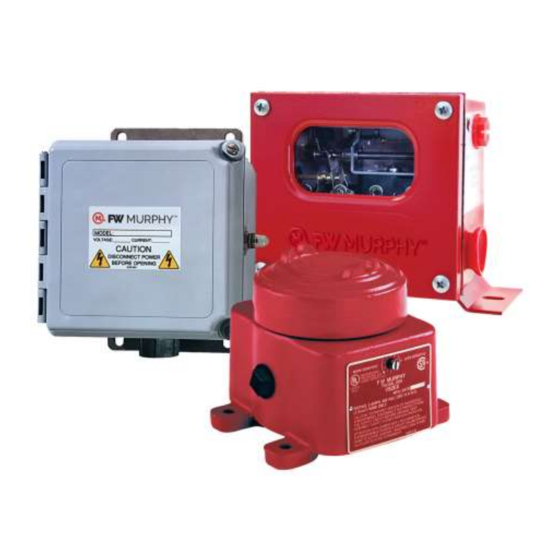
- Page 1 Shock/Vibration Control Switches Models: VS2, VS2C, VS2EX, VS2EXR, VS2EXRB and VS94 Installation Instructions 00-02-0185 2016-05-16 Section 20...
- Page 2 Disconnect all electrical power to the machine. Make sure machine cannot operate during installation. Follow all safety warnings of the machine manufacturer. Read and follow all installation instructions. Please contact FW Murphy immediately if you have any questions.
-
Page 3: Table Of Contents
VS94 Time Delay Adjustment ....................8 Typical Mounting Locations ......................9 Internal Switches ..........................10 Electrical ............................11 Specifications ........................... 12 VS2 and VS2C ....................... 12 VS2EX ........................... 12 VS2EXR ......................... 12 VS2EXRB ........................12 VS94 ..........................13 For UL Applications ......................13... - Page 4 THIS PAGE INTENTIONALLY LEFT BLANK...
-
Page 5: General Information
General Information Description The FW Murphy shock and vibration switches are available in a variety of models. They are used for applications on machinery or equipment where excessive vibration or shock can damage the equipment or otherwise pose a threat to proper operation. A set of contacts is held in a latched position through a mechanical latch and magnet mechanism. -
Page 6: Space Heater Options (Vs94 Only)
T24: Time delay for 24 VDC Space Heater Options (VS94 only) This optional space heater board prevents moisture from condensing inside the VS94 Series case. Options listed below: H15: Space heater for 115 VAC H24: Space heater for 24 VDC Section 20 00-02-0185 2016-05-16... -
Page 7: Dimensions
Dimensions Section 20 00-02-0185 2016-05-16 - 3 -... -
Page 8: Installation
Installation The VS2 and VS94 series shock switches are sensitive to shock and vibration in all three planes of motion – up/down, front/back and side/side. Front/back is the most sensitive (the reset push button is located on the front of the unit). For maximum sensitivity, mount the unit so that the front faces into the direction of machine rotation. -
Page 9: All Models
1. Firmly secure the unit to the equipment using the base foot mount or C-Clamp, if applicable. See C-Clamp Installation. For oil well pump jacks, attach the VS2 and VS94 Series to the Sampson post or walking beam. See Typical Mounting Locations. -
Page 10: Sensitivity Adjustment
THE MACHINE IS RUNNING. STAND CLEAR OF THE MACHINE AT ALL TIMES WHEN IT IS OPERATING. All models of the VS2 and VS94 Series cover a wide range of sensitivity. Each model is adjusted to the specific piece of machinery on which it is installed in a satisfactory location. - Page 11 WARNING: MAKE THE AREA NON-HAZARDOUS OR DE-ENERGIZE ALL CIRCUITS BEFORE OPENING THE EXPLOSION-PROOF (-EX) ENCLOSURES. WARNING: ROTATING SENSITIVITY ADJUSTMENT SCREW COUNTERCLOCKWISE / LESS SENSITIVE AFTER F LATCH HAS TRIPPED COULD DAMAGE THE ADJUSTMENT SHAFT. Depress the Reset button, and restart the machine. Repeat this process until the unit does not trip on start up.
-
Page 12: Vs94 Time Delay Adjustment
VS94 Time-Delay Adjustment 1. Apply power to the time-delay circuit. (See Electrical for the time-delay circuit). The time-delay function is initiated. 2. Time the length of the delay with a watch. Let time delay expire. After it expires, the override circuit will de-energize the solenoid, allowing the latch to trip. A clicking noise is heard. -
Page 13: Typical Mounting Locations
Typical Mounting Locations NOTE: These are typical mounting locations for best operation. Other mountings are possible. See Installation section for more information. Section 20 00-02-0185 2016-05-16 - 9 -... -
Page 14: Internal Switches
Internal Switches Section 20 00-02-0185 2016-05-16 - 10 -... -
Page 15: Electrical
Electrical Section 20 00-02-0185 2016-05-16 - 11 -... -
Page 16: Specifications
VS2 and VS2C Case: Environmental Protection: Ingress protected to IP54 (when mounted on a horizontal surface with drain holes down) VS2: Base Mount VS2C: C-Clamp mount. Includes 45’ (13.7M), 2-conductor 16 AWG, 30 strands/0.25mm strand diameter (1.5mm ) cable and five cable hold-down clamps ... -
Page 17: Vs94
Operating Temperature Range: -40 F to 185 F (-40 C to 85 Range adjustment: 0-7 G’s; 0-100 Hz/0.10 in. displacement VS94 Case: Polyester fiberglass reinforced; NEMA type 4 and 4X; IP66; CSA types 4 and 12 Conduit Fitting: ¾ NPT conduit fitting connection ... -
Page 18: Service Parts
Service Parts PART NO. DESCRIPTION 20000030 Movement assembly 20000031 Glass and gasket assembly 20000032 Reset push button assembly VS2C 20000030 Movement assembly 20000031 Glass and gasket assembly 20000032 Reset push button assembly 20050021 Mounting clamp 20000261 Cable clamp assembly (1 each) (VS2C) 20000137 5 clamps and 45 feet (13.7 meters) of cable (VS2C) VS2EX... - Page 19 THIS PAGE INTENTIONALLY LEFT BLANK...
Need help?
Do you have a question about the VS2 and is the answer not in the manual?
Questions and answers