
Related Manuals for Samlex Solar SCC-30AB

Summary of Contents for Samlex Solar SCC-30AB
- Page 1 30 Amp Owner's Please read this manual before Manual Solar Charge operating your charge controller. Controller SCC-30AB...
-
Page 2: Table Of Contents
INDEX 1. Safety Instructions ....................3 2. General Description of Solar System .............. 18 3. General information - Batteries ..............15 4. Principle of Operation & Features ..............21 5. Construction, Layout and Controls ..............33 6. Installation and Operation ................38 7. -
Page 3: Safety Instructions
SAFETY INSTRUCTIONS Please read these instructions before installing or operating the Charge Controller to prevent personal injury or damage to the Charge Controller. General Installation and wiring compliance • Installation and wiring must comply with the local and National Electrical Codes and must be done by a certified electrician. - Page 4 SAFETY INSTRUCTIONS batteries can produce a short circuit current high enough to weld a ring or the like to metal and cause a severe burn. • If you need to remove a battery, always remove the ground terminal from the battery first. Make sure that all the accessories are off so that you do not cause a spark.
-
Page 5: General Description Of Solar System
General Description of solar system Current (I),Voltage (V) and Power (P) Curves of a Solar Panel and how the Solar Panel is rated - V , Vmp , I Imp , Pmax sc , Fig. 2.1. Current (I),Voltage (V) and Power (P) Curves A Current (I) versus Voltage (V) Curve of a Solar Panel (“I-V”... - Page 6 General Description of solar system The power available from a photovoltaic device at any point along the curve is just the product of Current (I) in Amps (A) and voltages (V) at that point and is expressed in Watts. At the short circuit current point, the power output is zero, since the voltage is zero.
- Page 7 General Description of solar system I-V Curve for a typical 12V Solar Panel is shown in Fig. 2.2. The Open Circuit Voltage is 21V and the Short Circuit Current I = 2.7V. Maximum Power Point in the example curve given above is where Vmp is 17V, and the current Imp is 2.5A.
-
Page 8: General Information: Batteries
General Description of solar system The output current of the Solar Cell has a Positive Temperature Coefficient – the output current increases with the rise of temperature. However, it is negligible – less than 0.1 % / °C of the Short Circuit Current Isc. The output Voltage of the Solar Cell has a Negative Temperature Coefficient –... - Page 9 GENERAL INFORMATION: BATTERIEs Both the plates consist of a rectangular grid made out of alloyed Lead with rectangular holes in it as shown in Fig 3.1 below: Fig 3.1. Grid structure of Positive and Negative Plates in a Lead Acid Battery The holes in the grid of the plates are filled with a paste of active material made out of a mixture of Red Lead and 33% dilute Sulphuric Acid (different manufacturers use modified mixtures).
- Page 10 GENERAL INFORMATION: BATTERIEs • Lead-Calcium batteries have lower self-discharge rates and therefore, will draw less current while kept in storage Electrochemical Reactions during Charging and Discharging of Lead Acid Battery Electrical power in the Lead Acid Battery is produced by reversible electrochemical reactions as follows: During discharging, the Sulphuric Acid in the electrolyte reacts with the Positive and Negative plates resulting in conversion of the active materials in the two plates to...
- Page 11 GENERAL INFORMATION: BATTERIEs Sealed / VRLA batteries are designed to recombine the Hydrogen and Oxygen back into water and hence, Sealed / VRLA batteries are not required to be topped up with distilled water. That is why, these batteries are also called maintenance free batteries. Sealed / VRLA batteries use safety valves to release any excessive gas pressure built up inside the battery due to malfunction or overheating.
- Page 12 GENERAL INFORMATION: BATTERIEs then recharged. If an SLI battery is used for this type of deep discharge application, its useful service life will be drastically reduced. This type of battery is not recommended for the storage of energy for DC powered devices like lighting, radios, inverters, etc.
- Page 13 GENERAL INFORMATION: BATTERIEs Reduction in Usable Capacity at Higher Discharge Rates As stated above, the rated capacity of the battery in Ah is normally applicable at a discharge rate of 20 Hours. As the discharge rate is increased, the usable capacity reduces due to “Peukert Effect”.
- Page 14 GENERAL INFORMATION: BATTERIEs PERCENTAGE OF STANDING VOLTAGE OF Cell Voltage (12V BATTERy FULL CHARGE 12V NOMINAL BATTERy HAS 6 CELLS IN SERIES) 100% 12.63V 2.105V 12.6V 2.10V 12.5V 2.08V 12.3V 2.05V 12.2V 2.03V 12.1V 2.02V 12.0V 2.00V 11.8V 1.97V 11.7V 1.95V 11.6V 1.93V...
- Page 15 GENERAL INFORMATION: BATTERIEs Effect of Temperature on Battery Voltage The temperature of the electrolyte affects the rate of chemical reactions in the batteries as well as the rate of diffusion and the resistivity of the electrolyte. Therefore, the charging characteristics of the battery will vary with temperature. This is nearly linear and the Voltage Coefficient of Temperature Change is normally taken as -3 mV to -5 mV / ºC / Cell.
- Page 16 GENERAL INFORMATION: BATTERIEs Loss of Battery Capacity at Low Temperatures Batteries lose capacity in low temperatures. At 32ºF (0ºC), a battery will deliver about 70 to 80% of its rated capacity at 80ºF (26.7ºC). If the electrolyte temperature of the battery bank is lower than 80ºF (26.7ºC), additional batteries will be needed to provide the same usable capacity.
- Page 17 GENERAL INFORMATION: BATTERIEs Negative terminal of Battery 3 is connected to the Positive terminal of Battery 2. The Negative terminal of Battery 2 is connected to the Positive terminal of Battery 1. The Negative terminal of Battery 1 becomes the Negative terminal of the 24V battery bank.
- Page 18 GENERAL INFORMATION: BATTERIEs Caution! When 2 or more batteries / battery strings are connected in parallel and are then connected to a charger (See Fig. 3.3 and 3.4), attention should be paid to the manner in which the charger is connected to the battery bank. Please ensure that if the Positive output cable of the battery charger (Cable “A”) is connected to the Positive battery post of the first battery (Battery 1 in Fig.
- Page 19 GENERAL INFORMATION: BATTERIEs For example, backup energy may be required for say 4 hours or 1 day (24 Hours) or 3 days (72 Hours). In this connection, the following formulae will be applicable: FORMULA 1 DC Power in Watts (W) DC Volts (V) x DC Current (A) AC Volts (V) x AC Current (A) x Power FORMULA 2...
- Page 20 GENERAL INFORMATION: BATTERIEs application. As per Table 3.2 on page 13, the usable capacity at this higher discharge rate will be reduced to 60%. The actual capacity of the battery will have to be increased by 1.66 times. f) Further, for longer battery life, the battery should not be discharged deeply (Please refer to heading “Depth of Discharge and Battery Life”...
-
Page 21: Principle Of Operation & Features
/ panels Principle of Operation of Solar Charging with Series Type Pulse Width Modulation (PWM) Control The design and operation of SCC-30AB is based on Series Type PWM (Pulse Width Modu- lation) control at PWM frequency of 300 Hz. PWM Explanation In order to understand the working of the controller, it is necessary to understand the concept of PWM and Duty Cycle, which are explained with the help of Fig. - Page 22 PRINCIPLE OF OPERATION & FEATuREs SERIES MOSFET SWITCH ON = 0.83 ms OFF = 2.5 ms BATTERY 2.7A Pulse Width = ON Time SOLAR PANEL AVERAGE = 0.675A PULSE PERIOD = 3.33 ms 0.83 ms PULSE WIDTH FREQUENCY = = 300 Hz % DUTY CYCLE = = 25% PULSE...
- Page 23 In SCC-30AB, frequency of 300 Hz is used for optimum charging performance. Charging Algorithms Notes: For proper understanding of the charging algorithm, please read Section 3 –...
- Page 24 PRINCIPLE OF OPERATION & FEATuREs STAGE 2 EQUALIZATION ABSORPTION NIGHT NIGHT (1/2/3 HOURS) (1 HOUR) NIGHT NIGHT 100% DUTY STAGE 1 STAGE 3 FLOAT CYCLE BULK FLOAT TIME TIME Fig. 4.1A - Normal Charging Algorithm Fig. 4.1B - Equalization Algorithm Fig.
- Page 25 PRINCIPLE OF OPERATION & FEATuREs Stage - 1: Bulk Stage. During night, the battery voltage will drop below the Float Transition Voltage Set Point “Vf” (Curve portion A to B), as there is no sun and discharging takes place due to loads that are powered during the night e.g. night lighting.
- Page 26 PRINCIPLE OF OPERATION & FEATuREs (evolution of Hydrogen and Oxygen due to electrolysis of water in the electrolyte) and hence, it is necessary to exit this stage as soon as 100% capacity is restored. If this over voltage condition is allowed to continues after 100% recharging, the battery will be damaged due to effects of overcharging like overheating, loss of water, corrosion of the Positive plates and excessive build up of pressure resulting in acid spillage due to opening of pressure activated relief valves (sealed batteries).
- Page 27 PRINCIPLE OF OPERATION & FEATuREs the Float Voltage Regulation Set Point “Vf” continuously for around 1 hour, the controller reverts to Stage 1: Bulk Stage. PWM DUTY Cycle is changed to 100% and the LCD Screen 4 (Fig 5.3) changes to “State: Bulk”. Equalization Charging General Information on Equalization Caution!
- Page 28 PRINCIPLE OF OPERATION & FEATuREs and formation of more Lead Sulfate crystals. Voltages drop on discharging results in overheating and excessive voltage drop in the terminal voltage of the battery. Overall, this results in poor performance of the battery. Sulfation may be reduced partially by the stirring / mixing action of the electrolyte due to gassing and bubbling because of intentional overcharging during the Equalization Stage.
- Page 29 PRINCIPLE OF OPERATION & FEATuREs available as follows: • At the back of the unit - Fig 5.2 • Table 6.1 under heading “Standard Battery Charging Programs” on page 43 Automatic equalization after interval of 28 days or manual equalization can be selected with the help of DIP Switch 5 located at the back of the unit (Fig 5.2).
- Page 30 PRINCIPLE OF OPERATION & FEATuREs will be less than the programmed Equalization Voltage Set Point displayed on Screen 6 (Fig 5.3) under “EQU”. NOTE: Although the charger is in Bulk Stage, the LCD Screen 4 (Fig 5.3) displays “State: Equalization” and NOT “State: Bulk.” The Status LED will blink ORANGE, once per second.
- Page 31 PRINCIPLE OF OPERATION & FEATuREs Voltage Regulation Set Point “Ve” and maintain this voltage level for continuous or cumulative period of 1/2/3 Hours depending upon the programmed type of battery (Please see Table 6.1 under heading “Standard Battery Charging Programs” on page 43). If “Ve” cannot be maintained continuously for 1/2/3 Hrs due to inadequate charging current as a result of low / loss of sun light / charging current being diverted to load(s), the Equalization Mode will be carried forward till the programmed hours are completed or in other words, it will get locked in Equalization Stage (the...
- Page 32 PRINCIPLE OF OPERATION & FEATuREs Stage as explained above under heading “Automatic Equalization After 28 Days.” Termination of Equalization Stage in Manual Mode Before Completion: If the unit is set for manual Start / Stop of Equalization Stage (Using DIP Switch No. 5) and equalization is switched ON but is switched OFF before completion, the charger reverts to “Bulk Stage”...
-
Page 33: Construction, Layout And Controls
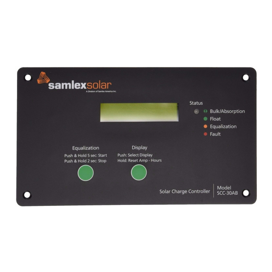
ConstruCtion, layout & Controls General SCC-30AB is designed for flush mounting on a wall / panel. The controls and indications are built on the Front Panel face plate that has 4 countersunk holes for flush mounting (Fig. 5.1). All the electronics, DIP switches for settings, terminal... - Page 34 ConstruCtion, layout & Controls Controls & Indications The description and the functions of the controls and indications are given below: Front Panel A single, 3-color LED (GREEN, RED, ORANGE) marked “Status” (2, Fig 5.1) is used to indicate charging stages and faults as given below in Table 5.1. LED Display for Charging Stages and Faults TABLE 5.1: LED Display Charging...
- Page 35 ConstruCtion, layout & Controls TABLE 5.2: Push Buttons BUTTONS ACTION Push to change the LCD display screens (Fig. 5.3) Display (3, Fig 5.1) Push and hold to reset Amp-Hours. When DIP Switch 5 is set at OFF, hold Restart / Stop Equalization Equalization for 5 sec to manually start equalization.
- Page 36 ConstruCtion, layout & Controls automatically set once a particular battery type corresponding to one of the 8 options has been programmed using DIP Switches 2,3,4 (See page 43, Table 6.1). SCREEN 7: Displays the heat sink temperature (Heatsink) in °C (the metal plate of the front panel acts as the heat sink).
- Page 37 ConstruCtion, layout & Controls LCD Display – Fault Messages The LCD display (1, Fig. 5.1) indicates the following fault messages when SCC-30AB stops operating. DISPLAy DESCRIPTION CAUSE OF FAULT Alarm: OC Over Current The current exceeds 150% of the rated current (45A)
-
Page 38: Installation And Operation
InstallatIon & operatIon Warning! • This unit will be damaged if the battery is connected in reverse polarity. • ENSURE that the battery + and - wires are correctly connected before proceeding. • Damage due to reverse battery connection is not covered under warranty! •... - Page 39 Running distance is the actual distance taking into consideration circuitous route followed by the wires for installation. • Current is the total Short Circuit Current Isc of the Solar Panel / Array. For SCC-30AB, maximum continuous current allowed is 30A. •...
- Page 40 / the panel for flush mounting. The front face plate of the SCC-30AB acts as the heat sink for the heat dissipating components mounted on the PCB at the back of the Front Panel face plate. Hence, please...
- Page 41 DC-BTS-A-C (optional) Fig. 6.2. Installation Diagram 3. The connections to the SCC-30AB terminals are shown in the drawing at Fig. 6.2. A barrier type of Terminal Strip has been provided for connecting the PV array and the battery. M-4 screws with clamping washers are used to make the connection.
- Page 42 As soon as Battery (+) is connected, the Status LED (2, Fig .1) will be steady Orange and message “Welcome to Samlex Solar 1.0” will be displayed for around 3 to 5 sec. After this, the LED will blink Green & Screen 1 (Fig 5.3) will be displayed: Amp 0.0;...
- Page 43 InstallatIon & operatIon Battery Types: SCC-30AB’s standard battery charging programs are suitable for a wide range of Lead-Acid battery types. These standard programs are select by DIP Switch 2~4. There is also one program for Ni-Cd battery (see Table 6.1).
- Page 44 (Table 6.1). Manual Equalization SCC-30AB is shipped with the DIP Switch 5 (Fig 5.2) set for manual equalization (OFF position). This is to avoid an unexpected or unwanted automatic equalization. In the Manual Mode, the push button marked “Equalization” (4, Fig 5.1) is used to both start and stop a manual equalization.
- Page 45 InstallatIon & operatIon Typical Equalization As soon as Equalization is activated, following indications will be seen: • Status LED (2, Fig 5.1) will blink Orange, once per second • Screen 4 (Fig. 5.3) will show “State: Equalization” • Screen 6 (Fig. 5.3) will display Equalization parameters related to the programmed battery type/charging algorithm (Table 6.1) •...
- Page 46 InstallatIon & operatIon The Battery Temperature Sensor (BTS) corrects the Absorption, Equalization & Float Voltage by the following values (reference temperature is 25ºC / 77ºF): • 12V battery: –0.030V per °C (–0.017V per °F). • 24V battery: –0.060V per °C (–0.033V per °F). The temperature sensed by the BTS at the battery is displayed on the LCD screen under the screen display “Heatsink BTS”...
-
Page 47: Troubleshooting
TroubleshooTing SCC-30AB is very rugged and designed for the most extreme operating conditions. Most PV system problems will be caused by connections,Voltage drops, and loads. Troubleshooting the SCC-30AB controller is simple. Some basic troubleshooting procedures are listed below. Protections & Fault Messages on the LCD Display & Fault LED Table 7.1 gives fault messages displayed on the LCD screen and status of the Red Fault... - Page 48 If it is unable to maintain its voltage, the battery may be failing. • Measure the PV Voltage and the Battery Voltage at the SCC-30AB terminals. If the voltage at the terminals is the same (within a few tenths of V) the PV array is charging the battery.
-
Page 49: Specifications
SpecificationS MODEL SCC-30AB INPUT MAX. OPEN CIRCUIT VOLTAGE (V ) OF SOLAR PANEL / ARRAY MAX. SHORT CIRCUIT CURRENT (I ) OF SOLAR PANEL / ARRAY TOTAL SELF CONSUMPTION CURRENT 50 mA OUTPUT / CHARGING TYPE OF CONTROLLER Series, Pulse Width Modulation (PWM) - Page 50 SpecificationS MODEL SCC-30AB PROTECTIONS OVER CURRENT Shut down at input current > 45A OVER TEMPERATURE OF HEAT SINK Temperature > 90°C: Disconnect panel / array (FACE PLATE) - Reconnect when cools down to 70°C ENVIRONMENTAL OPERATING TEMPERATURE RANGE 0°C to +45°C / 32°F to 113°F STORAGE TEMPERATURE RANGE -55°C to +85°C / - 67°F to 185°F...
-
Page 51: Warranty
5 yEAR LIMITED WARRANTy SCC-30AB manufactured by Samlex America, Inc. (the “Warrantor“) is warranted to be free from defects in workmanship and materials under normal use and service. The warranty period is 2 years for the United States and Canada, and is in effect from the date of purchase by the user (the “Pur- chaser“). - Page 52 Notes...
- Page 53 Notes...
Need help?
Do you have a question about the SCC-30AB and is the answer not in the manual?
Questions and answers