
Related Manuals for Vympel Hygrovision Mini


Summary of Contents for Vympel Hygrovision Mini
- Page 1 P r e c i s i o n | E c o n o m y | S a f e t y Operating Manual Hygrovision mini Dew point analyzer w w w . v y m p e l . d e...
-
Page 2: Table Of Contents
Purpose and applications.............. 4 Technical characteristics............... 5 Measurement principle..............6 Construction.................. 6 1.4.1! The Hygrovision mini’s main components and controls ......8! 1.4.2! Hygrovision mini power supply..............9! 1.4.3! Control and display elements ..............10! 1.4.4! Turning the Hygrovision mini on and off..........11! Menu of the Hygrovision mini............ - Page 3 3.2.1! Servicing the power supply unit IP-01 ............ 41! 3.2.2! Cleaning the condensation mirror............41! 3.2.3! Checking the efficiency of the thermoelectric battery (TEB)....43! 3.2.4! Replacement of the particle filter ............44! 3.2.5! Calibrating the Hygrovision mini ............. 44! Troubleshooting malfunctions............45 Error message codes..............46 Markings ................47 Packaging ................47...
-
Page 4: Analyzer Description
1 Analyzer description 1.1 Purpose and applications The Hygrovision mini is a compact analyzer designed to measure the dew points of wa- ter and hydrocarbons. This portable hygrometer (hereafter also analyzer) is an instrument that is designed to directly measure dew point temperatures by means of a temperature-controlled mirror. -
Page 5: Technical Characteristics
1.2 Technical characteristics Table 1 Water ≥ -50 °C (T housing Measurement range: Hydrocarbons ≥ -50 °C (T housing Water ±1 °C Absolute error Hydrocarbons ±1 °C Recommended volume of 0.3 – 0.5 N L/min sample gas stream 9 – 12.6 V Power supply: voltage current / power requirement 4 Ah / 15 W... -
Page 6: Measurement Principle
1.3 Measurement principle The Hygrovision mini analyzer registers the dew point of water or hydrocarbons in a gaseous mixture according to the principle of direct measurement, utilizing a mirror that can be heated and cooled. The measurement process involves monitoring the surface of the mirror and noting the tem- perature at the moment condensation forms on its surface. - Page 7 (battery), and a four-button control unit (button pad). Via the four-button control pad, the electronics unit makes it possible for the Hygrovision mini user to control how rapidly the condensation mirror is cooled and heated. The button pad is also used to turn the analyzer on and off, select the illumination system, and enter other operating commands.
-
Page 8: 1! The Hygrovision Mini's Main Components And Controls
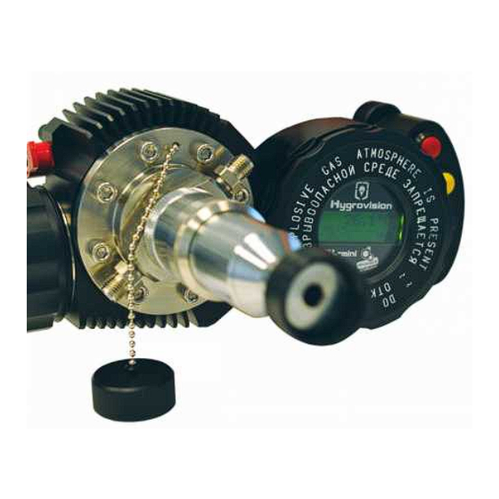
1.4.1 The Hygrovision mini’s main components and controls Illustration 1 Locking lid of the battery compartment Sample gas inlet nozzle Padded eyepiece Mirror illumination cable Sample gas outlet nozzle Ventilation channel for supplemental housing cooling Locking mechanism for the electronics unit cover... -
Page 9: Hygrovision Mini Power Supply
Housing body Ventilation channel for supplemental mirror cooling Focus control ring Battery compartment lid locking mechanism 1.4.2 Hygrovision mini power supply The analyzer is equipped with an independent source of electricity: power supply unit IP-01 (battery). Attention! The battery should only be charged using the specially designed charging unit. -
Page 10: Control And Display Elements
1.4.3 Control and display elements Illustration 3 Refer to the table below for the function(s) of individual buttons Pos. Description Color Function Analyzer on/off; Return to main menu without saving or applying “Menu” changes; Quick access to the main menu Open the main menu;... -
Page 11: Turning The Hygrovision Mini On And Off
Information about the current measurement as well as information about the system is displayed on the LCD screen (pos. 5, illus.3). 1.4.4 Turning the Hygrovision mini on and off Hold down the menu button (red) for a few seconds to turn the analyzer on (pos. -
Page 12: Menu Of The Hygrovision Mini
1.5 Menu of the Hygrovision mini 1.5.1 Menu structure... -
Page 13: Main Menu
This temperature will be maintained until the cleaning program is completed. The factory preset mirror-cleaning temperature is +55 °С. In cleaning mode, the Hygrovision mini displays the following information (illus. 5): • Program code (M10);... -
Page 14: 4! "Measuring The Dew Point: Т Dp
To leave the cleaning mode, press the menu button. 1.5.4 “Measuring the dew point: Т ” Illustration 6 Make sure the analyzer is turned on and select the “Dew point measurement” mode. Use the “up” and “down” buttons to scroll through the menu points and push the “se- lect”... -
Page 15: Settings
1.5.5 “Settings” Illustration 7 The main operating parameters for the analyzers can be adjusted under the Illustration 7 “Settings” menu ( ). These parameters are: Heating temperature • Temperature change interval for mirror cooling during the measurement cycle in • °С... - Page 16 1.5.6 Status of the battery charge Illustration 8 Under this menu, specific parameters regarding the status of the battery (IP 01) can be Illustration 8 viewed on the analyzer’s display ( Table lists the most important parameters and the respective minimum and maximum value tolerances.
- Page 17 1.5.7 Program codes Each of the analyzer’s program points has its own code, which is shown in the upper left hand corner of the display. Table 5 shows a list of these program codes. Table 5 Code Program point М10 Mirror cleaning М20 Measurement...
-
Page 18: Accessories And Additional Equipment
1.6 Accessories and additional equipment A number of accessories and additional equipment are included with delivery of the Hygrovision mini. A list of these items is provided under point 2.6 / Table 5. 1.6.1 Battery charger Illustration 9 In order to charge the analyzer’s battery (IP 01), a specially designed battery charger is included with delivery. -
Page 19: 3! Through-Flow Control System
1.6.3 Through-flow control system Illustration 11 Illustration 11 The through-flow control system consists of a fine control valve ( Pos.2), manometer (Pos.3), rotameter with protective housing (Pos.5), and a quick- connect coupler (Pos.4). This system makes it possible to control and regulate the flow of sample gas into the measurement chamber. -
Page 20: 5! Filter For The Control Of Heavy Hydrocarbons
1.6.5 Filter for the control of heavy hydrocarbons Illustration 13 The filter for the control of heavy hydrocarbons is included with delivery of the analyzer. It is intended for insertion as an additional control while measuring the dew point of wa- ter, when the sample gas contains a large quantity of glycols and heavy hydrocarbons. -
Page 21: Hygrovision Mini Set
1.7 Hygrovision mini set Illustration 15 Table 6 Designation Description Pos. No. Notes Included in Delivery The «Hygrovision mini» dew point analyzer set includes the following equipment and accesso- VMPL2.844.001 ries: KRAY3.821.003 Microscope VMPL4.841.001 Microscope cable VMPL4.161.001 Transportation case VMPL5.122. 001 Battery charger VMPL5.549.001... - Page 22 AC adapter (220V) Particle filter replacement cartridge (gas delivery system FE73A-15 insert) DGV-2-S Seal VMPL.248.005 Sealing ring Mounting connector set DMC6M-20M15- Connector with external threads Dk-Lok DMC6M-8R-SA Connector with external threads Dk-Lok DMC6M-8G-SA Connector with external threads Dk-Lok DFSA-D-6M-SA Quick-connect coupler Dk-Lok Operating documentation VMPL2.844.001M Testing documentation...
-
Page 23: Explosion Safety Provisions
GOST R 52350.0 and GOST R 52350.1. The maximal temperatures generated through internal heating, to which the electrical components and the housing of the Hygrovision mini are exposed do not exceed those allowed in GOST R 52350.0 for temperature class T5. -
Page 24: Markings
All applicable explosion protection information is displayed on the housing of the Hygrovision mini as required by regulation. 1.9 Markings Markings on the analyzer’s housing provide the following information: ! Trademark and name of the manufacturer ! Name of the device... -
Page 25: Proper Operation Of The Hygrovision Mini
126. 2.1.3 General safety measures In terms of protection against electrical shock, the Hygrovision mini is a Class 0I (GOST norms 12.2.007.0 SSB) electrical device The Hygrovision mini may not be used to take dew point measurements of aggressive media or in an aggressive environment. - Page 26 The valve of the gas sampling system must be closed and the pressure within the sampling system must be adjusted to match ambient atmospheric pressure using the needle valve before the analyzer is connected to or disconnected from the sample de- livery pipe.
-
Page 27: Using The Hygrovision Mini
2.3 Using the Hygrovision mini 2.3.1 Preparing to take dew point measurements Switch on the Hygrovision mini portable dew point analyzer as described in the hand- book above. Slowly open the gas delivery system valve while watching the associated manometer, in order to monitor the increase in pressure in the measurement chamber. -
Page 28: 2! Visual Identification Of Water Condensation
2.3.2 Visual identification of water condensation Illustration 18 Illustration 19 When using the Hygrovision mini, the operator can observe the condensation of water vapor utilizing either side lighting or vertical lighting. Under side lighting, the dark surface of the mirror appears to become evenly covered with red spots as condensation forms (illustration 18). -
Page 29: 3! Visual Identification Of Hydrocarbon Condensation
Illustration 23 Illustration 22 Under side lighting, the ice crystals that form appear as clear luminous red patches when viewed through the microscope (illustration 22). Under vertical lighting, the ice crystals that form appear as branching dark patches on a light background when viewed through the microscope (illustration 23). 2.3.3 Visual identification of hydrocarbon condensation The condensation of hydrocarbons (HCs) can only be observed under vertical lighting. - Page 30 Illustration 26 Illustration 25 Octane and higher hydrocarbons condense on the surface of the mirror in the form of small, dilute dark spots. As the mirror continues to cool, these small spots slowly form into droplets (illustration 26). As the cooling process continues, the small condensation droplets slowly collect to more completely cover the mirror’s surface, until it becomes noticeably darkened.
-
Page 31: 4! Rough Dew Point Measurement
2.3.4 Rough dew point measurement Rough dew point measurements serve to establish the temperature range within which the dew point is to be found. Rough dew point measurements are made exclusively us- ing the incremental cooling process (manual mode). To change the cooling parameter settings select the menu point “Cooling parameters” "... - Page 32 Illustration 27...
-
Page 33: 5! Measuring Water And Hydrocarbon Dew Points
When the device is first switched on, all temperatures shown on the display (mirror condensation temperature; housing temperature and target temperature) may vary by up to ± 0.2 °C. The value for the condensation mirror temperature is determined by the sum of the housing temperature value and the heating/cooling temperature value. - Page 34 mode is shown in illustration 31. When taking water dew point measurements in automatic cooling mode, push the Down button to fix the temperature at which condensation occurs, and to fix the tem- perature at which evaporation occurs push the Up button. The dew point value will be calculated as the mean of these two temperatures (the condensation and evaporation points) in automatic cooling mode and shown on the analyzer’s display.
- Page 35 Illustration 31...
- Page 36 Illustration 32...
-
Page 37: 6! Supplemental Cooling
2.3.6 Supplemental cooling !35,0& !40,0& !45,0& !50,0& !55,0& !60,0& 9.0&MPa& !65,0& 2.7&Mpa& 0.1&MPa& !70,0& !75,0& 0& 5& 10& 15& 20& 25& 30& 35& 40& Housing temperature °C Illustration 24 The graph in illustration 29 shows the effectiveness of the supplemental cooling sys- tem. -
Page 38: Deinstallation Of The Hygrovision Mini
S(Item 5) in order to properly vent used gas. Water or natural gas may also be used as supplemental coolant media. Illustration34 2.4 Deinstallation of the Hygrovision mini Use the following procedure to uninstall the analyzer: 1) Switch off the analyzer;... -
Page 39: Maintenance
3 Maintenance Analyzer maintenance consists of regular metrological recalibration, checks of the technical condition and, if necessary, cleaning the condensation mirror and replacing filter elements. Proper storage, transport, and operational conditions will ensure that the analyzer’s metrological characteristics continue to conform to the relevant prescribed standards. 3.1 Function tests When the analyzer is switched on, the following function tests should be carried out: Charge status and condition of the battery pack (IP-01) -
Page 40: 2! Check The Condensation Mirror
3.1.2 Check the condensation mirror Perform a visual inspection of the state of the surface of the condensation mirror using the microscope. Be sure to adjust the focus if necessary. The condition of a clean condensation mirror surface may differ slightly from the illus- trations in Appendix D. -
Page 41: 1! Servicing The Power Supply Unit Ip-01
3.1.5 Perform a leak test After the device is installed, all gas-sample line connections must be examined for leaks in the following manner: Close the valve of the flow control system • slowly open the inlet valve of the sampling line and the valve at the inlet of the ana- •... - Page 42 3. After reaching the desired target temperature select “Mirror cleaning” mode again. Repeat this process up to three times if necessary. If there is no improvement in the condition of the mirror’s surface after repeated cycles in the “Mirror cleaning” mode, it will be necessary to clean the mirror manually. Everything required for this procedure is included with delivery.
-
Page 43: Checking The Efficiency Of The Thermoelectric Battery (Teb)
Using the special key provided (VYMP 8.392001), turn the sleeve containing the inte- grated observation window counter-clockwise and remove it from the gas delivery sys- tem (illustration 36). Clean the surface of the condensation mirror with an applicator dipped in the cleaning fluid (illustration 37). Illustration 36 Illustration 37 Please note:... -
Page 44: 4! Replacement Of The Particle Filter
6. Screw the inlet nozzle back into the sample delivery unit of the housing 3.2.5 Calibrating the Hygrovision mini Calibration of the Hygrovision mini involves shifting the analyzer’s standard calibra- tion curve to reflect a set value within the analyzer’s measurement range. -
Page 45: Troubleshooting Malfunctions
3.3 Troubleshooting malfunctions Possible technical failures as well as the appropriate responses in each case are presented in Table 7. Table 7 Failure Possible cause Response options The analyzer won’t switch The battery charge is too low. (Re)charge the battery. a) The battery temperature ex- ceeds tolerable limits (0 °C –... -
Page 46: Error Message Codes
Use supplemental cool- c) High operating pressure ing of the analyzer hous- or housing temperature (see point 4,5) a) From time to time the analyzer switches off un- Ensure that the battery lid The battery is not expectedly. is aligned correctly and properly (securely) screw it down tight. -
Page 47: Markings
4 Markings Labeling on the analyzer’s housing provides the following information: Trademark and name of the manufacturer Name of the device Explosion protection labeling Certifying Authority and Certificate Number Information label about protection against the effects of solids and water according to IEC 60529:1992 (IP54) Dew point measurement range Operating pressure limit... -
Page 48: Transportation
Likewise they present no risk to produc- tion and storage spaces. Hygrovision mini analyzers that are no longer being used may be disposed of in any way deemed appropriate by the user. Old disused batteries are to be turned over to companies that are licensed and/or... -
Page 49: Anlage А
Anlage А Factory settings Table 9 Unit of Measurement Code Parameter Value measurement range M 31 Warming temperature 0 – 60 °C M 32 Change interval 0 – 10 °C °C / min M 33 Cooling rate 0 – 10 M 34 Calibration factor -10 –... -
Page 50: Sample Extraction System
Appendix B Sample extraction system Illustration 39 The sample extraction system is intended for permanent installation on the main gas line. This apparatus makes possible the extraction of a gas sample at the exist- ing working pressure. The sample extraction system is mounted onto the pipe by means of an installation bushing (Illustration 39, pos. -
Page 51: Membrane Filter (Kray6.457.022)
Appendix C Membrane Filter (KRAY6.457.022) Function The membrane filter is designed to remove from the gas sample the liquids and par- ticulate matter that could contaminate or damage the analyzer’s measuring chamber or the components of the sampling unit. Description The filter consists of a housing and a membrane. -
Page 52: Technical Data
Technical Data Maximum operating pressure 250 bar Recommended maximum gas flow volume through 72,000 cm / min the membrane: 130-502 Gas flow volume through the membrane: 130-502 14,400 cm / min Housing material / sealing ring material Stainless steel / Viton KRAY6.457.022 Illustration 30 Dimensions (mm):... - Page 53 Illustration 43 For version 1, the filter is mounted in such a way that liquids seperated from the gas stream return to the sample source. In this configuration ( Illustration 43) the filter is mounted vertically, immediately downstream of the sample extraction point (Pos.2).
-
Page 54: Anlage D
Anlage D Examples of the appearance of water and hydrocarbon condensation (Microscope perspective) Condensation mirror as seen Condensation mirror as seen under side lighting under vertical lighting Absence of condensation (individual red dots and scratches are acceptable) Illustration 45 Illustration 46 Condensation mirror showing water con- densation... - Page 55 Water condensation in both liquid and crystaline phases Illustration 49 Illustration 50 Water condensation in crystaline phase only Illustration 51 Illustration 52 Hydrocarbon condensation (inc. heptane) Illustration 53 Illustration 54...
- Page 56 Hydrocarbon condensation (Octane and higher ranked HCs) Illustration 56 Illustration 55...
-
Page 57: Appendix E
Appendix E Illustration 57... -
Page 58: Appendix F
Appendix F Page: Number of Document No. Adjusted Replaced New Cancelled documents number: Signature Date...
Need help?
Do you have a question about the Hygrovision Mini and is the answer not in the manual?
Questions and answers