Table of Contents
Advertisement
Controller Instruction
1
General information
Printed Matter Number
Applicable to
Preliminary Operations:
Safety Instructions
Persons Required
Special Tools
Consumables
2
Document Overview
This document describes the following:
1
General information............................................................................................................................................................ 1
2
Document Overview ........................................................................................................................................................... 1
3
General description ............................................................................................................................................................ 4
3.1
Introduction .................................................................................................................................................................. 4
3.2
Automatic control of the compressor ............................................................................................................................ 4
3.3
Protecting the compressor ........................................................................................................................................... 4
3.3.1
Shut-down ........................................................................................................................................................... 4
3.3.2
Shut-down warning .............................................................................................................................................. 5
3.4
Service warning............................................................................................................................................................ 5
3.5
Automatic restart after voltage failure ........................................................................................................................... 5
4
Detailed description of the control panel ............................................................................................................................ 6
5
Icons used .......................................................................................................................................................................... 7
5.1
Status icons ................................................................................................................................................................. 7
6
Main screen ....................................................................................................................................................................... 9
7
Shut-down warning .......................................................................................................................................................... 10
7.1
Description ................................................................................................................................................................. 10
7.2
Compressor element outlet temperature .................................................................................................................... 10
7.3
Dewpoint temperature ................................................................................................................................................ 11
8
Shut-down ........................................................................................................................................................................ 12
8.1
Description ................................................................................................................................................................. 12
8.2
Compressor element outlet temperature .................................................................................................................... 12
8.3
Motor overload ........................................................................................................................................................... 13
9
Service warning ............................................................................................................................................................... 14
02/04/2013
PM 2946 7002 09
ES 4000 STANDARD
:
2946 7002 09
:
MB compressors
:
-
:
General
:
1
:
-
:
-
Page 1 of 39
Advertisement
Table of Contents

Related Manuals for Chicago Pneumatic ES 4000 STANDARD


Summary of Contents for Chicago Pneumatic ES 4000 STANDARD
-
Page 1: Table Of Contents
Controller Instruction General information ES 4000 STANDARD Printed Matter Number 2946 7002 09 Applicable to MB compressors Preliminary Operations: – Safety Instructions General Persons Required Special Tools – Consumables – Document Overview This document describes the following: General information................................1 Document Overview ................................ - Page 2 Description ................................. 14 Scrolling through all screens ............................15 10.1 Description ................................15 10.2 Overview of the screens ............................15 10.2.1 Overview of the Digital input screens ........................ 15 10.2.2 Overview of the Parameter screens ........................15 10.2.3 Overview of the Protections screens ......................... 16 10.2.4 Overview of the Test screens ..........................
- Page 3 32.2 Example of protection screens..........................36 32.3 Changing the settings ............................36 Test screens................................37 33.1 Display test ................................37 33.2 Safety valve test ..............................37 33.3 Production test ............................... 37 Programmable settings .............................. 38 34.1 Parameters: unloading/loading pressures ......................38 34.2 Parameters fix speed drive ............................
-
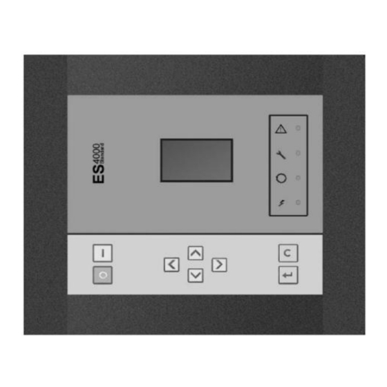
Page 4: General Description
General description View of the ES 4000 Standard controller Introduction The electronic controller has following functions: • Controlling the compressor • Protecting the compressor • Monitoring components subject to service • Automatic restart after voltage failure Automatic control of the compressor The controller maintains the net pressure between programmable limits by automatically loading and unloading the compressor. -
Page 5: Shut-Down Warning
3.3.2 Shut-down warning A shut-down warning level is a programmable level below the shut-down level. If one of the measurements exceeds the programmed shut-down warning level, this will also be indicated to warn the operator before the shut-down level is reached. Service warning If the service timer exceeds a programmed value, this will be indicated on the display to warn the operator to carry out some service actions. -
Page 6: Detailed Description Of The Control Panel
Detailed description of the control panel Function keys of the controller Ref. Designation Function Display Shows icons and operating conditions. Automatic operation symbol LED, Automatic operation Indicates that the regulator is automatically controlling the compressor: the compressor is loaded, unloaded, stopped and restarted depending on the air consumption and the limitations programmed in the regulator. -
Page 7: Icons Used
Icons used Status icons Name Icon Description Compressor status When the compressor is stopped, the icon stands still. When the compressor is running, the icon is rotating. Motor stopped Running unloaded Running loaded Machine control mode Remote start / stop LAN control Automatic restart after Automatic restart after voltage failure is active... - Page 8 Name Icon Description Temperature unit Hours (always shown together with seconds) Percent The value shown must be multiplied by 10 to get the actual value The value shown must be multiplied by 100 to get the actual value The value shown must be multiplied by 1000 to get the actual value Motor (overload) Element outlet temperature Filter...
-
Page 9: Main Screen
Main screen When the voltage is switched on, the first screen is a test screen. The next screen is the Main screen, shown automatically. The Main screen shows: • The compressor status by means of pictographs • The air outlet pressure Always consult your supplier if the pressure on the display is preceded by a "t". -
Page 10: Shut-Down Warning
Shut-down warning Description A shut-down warning will appear in the event of: • Too high a temperature at the outlet of the compressor element. • Too high a dewpoint temperature (Full-Feature compressors). Compressor element outlet temperature If the outlet temperature of the compressor element exceeds the shut-down warning level (see section Programmable settings), warning LED (5) starts blinking. -
Page 11: Dewpoint Temperature
Dewpoint temperature On compressors with integrated dryer, alarm LED (5) will light up and the related pictograph will appear flashing if the dewpoint temperature exceeds the warning level (programmable). Main screen with the dewpoint temperature warning The related pictograph will appear flashing: Press the Scroll button (12) until the actual dewpoint temperature appears. -
Page 12: Shut-Down
Shut-down Description The compressor will be shut down: • In case the temperature at the outlet of the compressor element exceeds the shut-down level. • In case of error of the outlet pressure sensor. • In case of overload of the drive motor. •... -
Page 13: Motor Overload
Motor overload In the event of motor overload, the compressor will be shut-down, alarm LED (5) will flash, automatic operation LED (3) will go out and the following screen will appear. Main screen with shut-down indication, motor overload Switch off the voltage. Remedy the trouble. -
Page 14: Service Warning
Service warning Description A service warning will appear when the service timer has reached the programmed time interval. If the service timer exceeds the programmed time interval, alarm LED (5) will light up. Press Scroll buttons (12) to scroll to <d.6>. The service symbol is shown. -
Page 15: Scrolling Through All Screens
10 Scrolling through all screens 10.1 Description Scroll buttons (12) can be used to scroll through all screens. The screens are divided into register screens, measured data screens, digital input screens (numbered as <d.in>, <d.1>, ...), parameter screens (numbered as <P.01>, <P.02>, ...), protections screens (numbered as <Pr.01>,...) and test screens (numbered as <t.01>,...). -
Page 16: Overview Of The Protections Screens
Parameter screens Designation Related topic <P.04> Pressure band settings See section Calling up/modifying pressure band settings <P.05> Setting a pressure band selection See section Modifying the pressure band selection <P.06> Modifying a service timer See section Calling up/modifying service timer settings <P.07>... -
Page 17: Menu Flow
10.3 Menu flow Simplified menu flow 02/04/2013 PM 2946 7002 09 Page 17 of 39... - Page 18 Compressor outlet pressure (16) Pressure band setting Compressor outlet temperature (17) Service timer settings Dewpoint temperature (18) Temperature unit Digital input status (19) Unit pressure Running hours (20) Auto restart Motor starts (21) Selection Y-D/DOL Module hours (22) Load delay time Loading hours (23) Minimum stop time...
-
Page 19: Calling Up Outlet And Dewpoint Temperatures
11 Calling up outlet and dewpoint temperatures Starting from the Main screen: Press Scroll button (12). The outlet temperature will be shown. The screen shows that the outlet temperature is 82 ˚C. For Full-Feature compressors: Press Scroll button (12). The dewpoint temperature will be shown: The screen shows that the dewpoint temperature is 3 ˚C. -
Page 20: Calling Up Running Hours
12 Calling up running hours Starting from the Main screen: Press Scroll button (12) until <d.1> is shown. Press Enter button (13). The screen shows the unit used (x1000 hrs) and the value (11.25): the running hours of the compressor are 11250 hours. -
Page 21: Calling Up Module Hours
14 Calling up module hours Starting from the Main screen: Press Scroll button (12) until <d.3> is shown. Press Enter button (13). A screen similar to the following appears The screen shows the unit used (hrs) and the value (5000): the regulator module has been in service during 5000 hours. -
Page 22: Calling Up Load Relay
16 Calling up load relay Starting from the Main screen: Press Scroll button (12) until <d.5> is shown. Press Enter button (13). This screen shows the number of unload to load actions (x 1 or - if <x1000> lights up - x 1000). In the above example, the number of unload to load actions is 10100. -
Page 23: Calling Up/Resetting The Service Timer
17 Calling up/resetting the service timer 17.1 Calling up the service timer Starting from the Main screen: Press Scroll button (12) until <d.6> is shown. Press Enter button (13). This screen shows the unit used <hrs> (or <x1000 hrs>) and the value <1191>. In the example shown, the compressor has run 1191 hours since the previous service. -
Page 24: Selection Between Local, Remote Or Lan Control
18 Selection between local, remote or LAN control Starting from the Main screen: Press Scroll button (12) until <P.01> is shown. Press Enter button (13). The actually selected control mode is shown: • <LOC> for local control • <rE> for remote control •... -
Page 25: Calling Up/Modifying Can Address Control
19 Calling up/modifying CAN address control 19.1 Calling up Starting from the Main screen: Press Scroll button (12) until <P.02> is shown. Press Enter button (13). If necessary enter the password. The next screen shows that the function is ON or OFF. Press the Enter button (13) to change this mode. -
Page 26: Modifying The Node Id
19.2 Modifying the Node ID The Node ID can be changed; use a value between 1 and 31. When the function is ON, the parameters cannot be modified. Change the function to OFF to change the node ID. It is also possible to change the channels. The controller has 4 channels. When changing the channels, the controller can act as a Mk IV controller (a previous version of the controller). -
Page 27: Calling Up/Modifying Ip, Gateway And Subnetmask
20 Calling up/modifying IP, Gateway and Subnetmask 20.1 Calling up Starting from the Main screen: Press Scroll button (12) until <P.03> is shown. Press Enter button (13). The next screen shows that the function is ON or OFF. If ON, press the Enter button (13) to modify it to OFF. Use the Scroll buttons Up or Down (12) to scroll between the items in this list: •... -
Page 28: Modification
20.2 Modification Press the Enter button (13). If necessary enter the password. The first digits are blinking. Use the Scroll buttons Up or Down (12) to modify the settings. Press Enter (13) to confirm. Modify the next digits the same way. The standard IP address is set as 192.168.100.100. 02/04/2013 PM 2946 7002 09 Page 28 of 39... -
Page 29: Calling Up/Modifying Pressure Band Settings
21 Calling up/modifying pressure band settings 21.1 Calling up the settings Starting from the Main screen: Press Scroll button (12) until <P.04> is shown. Press Enter button (13). Pressure band 1 (<Pb.1>) is shown on the display. Button (12) can be used to scroll to pressure band 2 (<Pb.2>). Press the Enter button (13) on the desired pressure band. -
Page 30: Modification
21.2 Modification Press Enter button (13) to modify the load level (value starts blinking). A password may be required. Use Scroll buttons (12) to change the loading pressure. Press Enter button (13) to program the new values or press the Escape button (14) to cancel. 22 Modifying the pressure band selection Starting from the Main screen: Press Scroll button (12) until <P.05>... -
Page 31: Calling Up/Modifying The Unit Of Temperature
24 Calling up/modifying the unit of temperature Starting from the Main screen: Press Scroll button (12) until <P.07> is shown. Press Enter button (13). The actually used unit is shown. Possible settings are <˚C> and <˚F>. Press Enter button (13) Unit starts blinking. -
Page 32: Activating Automatic Restart After Voltage Failure
26 Activating automatic restart after voltage failure This function allows the compressor to restart automatically after a power failure. This parameter, accessible in screen <P.09>, can only be modified after entering a code. Consult your supplier if this function is to be activated. 27 Selection between Y-D or DOL starting Starting from the Main screen: Press Scroll button (12) until <P.10>... -
Page 33: Calling Up Modifying Load Delay Time
28 Calling up modifying load delay time Starting from the Main screen: Press Scroll button (12) until <P.11> and the compressor load pictograph is shown. Press Enter button (13). This screen shows the load delay time (10) and the unit <s> seconds. To modify this value press the Enter button (13) (a password may be required). -
Page 34: Activating Password Protection
30 Activating password protection Important settings such as the setting of the service timer, pressure band setting, control mode settings,... can be protected by a password. Starting from the Main screen: Press Scroll button (12) until <P.13> is shown. Press Enter button (13). Password (<PASS>) appears on the screen. -
Page 35: Activate Load/Unload Remote Pressure Sensing
31 Activate load/unload remote pressure sensing Starting from the Main screen: Press Scroll button (12) until <P.14> is shown. Press Enter button (13). The function of this screen is to activate the remote load/unload relay. To be able to activate this remote Load/Unload functionality, a physical digital input with function Load/Unload is required. -
Page 36: Example Of Protection Screens
32.2 Example of protection screens Protection setting element outlet temperature Warning alarm high element outlet temperature 32.3 Changing the settings Starting from the Main screen (the example given describes the protection of the element outlet temperatures). Press Scroll buttons (12) until <Pr.> followed by a number and the element outlet temperature pictograph is shown. Press Enter button (13). -
Page 37: Test Screens
33 Test screens 33.1 Display test Starting from the Main screen. Press Scroll buttons (12) until <t.01> is shown. Press Enter button (13). The display now shows all icons that can be displayed. 33.2 Safety valve test In the test screen <t.02>, a safety valve test is provided. The safety valves can only be tested after entering a code. -
Page 38: Programmable Settings
34 Programmable settings 34.1 Parameters: unloading/loading pressures Minimum setting Factory setting Maximum setting Unloading/loading pressures Compressor data Compressor data Compressor data 34.2 Parameters fix speed drive Minimum setting Factory setting Maximum setting Motor running time in star Load delay time (star-delta) Number of motor starts starts/day Minimum stop time... -
Page 39: Terminology
34.5 Terminology Term Explanation ARAVF Activating automatic restart after voltage failure. Power recovery time Is the period within which the voltage must be restored to have an automatic restart. Is accessible if the automatic restart is activated. To activate the automatic restart function, consult your supplier. Restart delay This parameter allows to program that not all compressors are restarted at the same time after a power failure (ARAVF active).
Need help?
Do you have a question about the ES 4000 STANDARD and is the answer not in the manual?
Questions and answers
How do you input a password and is it 9989?
Como tirar alarme de proteção falha do inversor do motor principal