Advertisement
Quick Links
Advertisement

Related Manuals for Dennard 2055

Summary of Contents for Dennard 2055
- Page 1 ISSUE 2 SOFTWARE V.4…2226...
-
Page 2: Table Of Contents
Pan and Tilt Axes Excursions Factory Defaults Operation with a Control Panel Operation through Dome internal Menu Structure Operator Menu Supervisor Menu Technician Menu Menu Flow Chart APPENDIX.1. Type 2055 Access from various controllers APPENDIX.2. Trouble shooting guide 2055 Menu System Manual Sheet.1... -
Page 3: The Dennard 2055 Dome
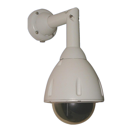
THE DENNARD TYPE 2055 DOME CAMERA The Dennard 2055 Dome Camera is a precision unit, offering a wide variable speed range, together with a large pre-set memory for positions, sequences (tours) and alarm response. It has a switchable colour/monochrome camera (colour only on indoor units) with an 18:1 zoom lens plus x 4 digital enhancement. -
Page 4: Programmable Features
Programmable Features The Dennard 2055 Dome Camera has a number of features which can be selected by the system supervisor when the dome is installed. Any of these can be altered subsequently, at any time, or cancelled altogether as relevant, to give the best operational responses for any particular application. -
Page 5: Sectors
1.1.12 Joystick Range Even if the control panel has a wide range proportional joystick output, the Dennard Dome has such a wide speed range that both a fast and a slow speed range are needed to realise the full performance (provided of course that the control panel in question has a facility to invoke these separately). -
Page 6: Host Polling
1.1.14 Error Reporting The Dennard Dome constantly monitors its own health, and should any difficulties occur (for instance, with dome protocol responses enabled it will be able to signal that there is an intermittent serial control problem, which would otherwise be undetectable) is able to indicate what may be wrong by a flashing square in the top right hand corner of the transmitted picture;... -
Page 7: Unit Health Monitoring
This will vary between control panels: refer to the Controller Manual. Operation through a Dome Menu Structure using Dennard controllers The 2055 Dome Camera is an open protocol device; consequently there will be several different manufacturers controllers available to drive it. All of the many features offered by the dome are programmed from one of three menu structures. - Page 8 When all three digits have been selected, Accept Entry will invoke that choice and the screen will automatically clear to the camera signal. To change the choice ‘Clear Entry’ will start the process again 2055 Menu System Manual Sheet.7...
- Page 9 THE FACTORY SET PASSWORD, (WHICH CAN BE CHANGED BY THE TECHNICIAN OR SUPERVISOR) IS PRINTED ON A LOOSE LEAF PAGE OF THIS MANUAL.TO PREVENT UNAUTHORISED CHANGES BEING MADE TO SETTINGS OR SET-UPS IT IS ADVISED THAT PASSWORDS ARE KEPT IN A SAFE PLACE. 2055 Menu System Manual Sheet.8...
-
Page 10: Operator Menu
Position’ option selected. The display will revert to one almost identical to the one used for recalling a Position. Position Number _ _ _ 0 1 2 3 4 5 6 7 8 9 Accept Entry Clear Entry Exit Erase from NVM 2055 Menu System Manual Sheet.9... - Page 11 When all five characters are completed and then accepted, the display clears the entry ready to receive the next ‘data block’, until all entries are complete and the Sequence is itself stored. 2055 Menu System Manual Sheet.10...
- Page 12 , 0 1 2 3 4 5 6 7 8 9 * = + Backspace Set Insert Mode Cancel edit Accept edit 2055 Menu System Manual Sheet.11...
- Page 13 0 1 2 3 4 5 6 7 8 9 Accept Entry Clear Entry Cancel Key in your new PIN (password) and accept the entry. Make a note of the new PIN number and keep it in a safe place 2055 Menu System Manual Sheet.12...
- Page 14 To add another privacy patch you will have to enter the Supervisor Menu again and repeat the whole of the above procedure. Clear all privacy patches when invoked will remove ALL previously stored privacy patches. 2055 Menu System Manual Sheet.13...
- Page 15 The second Technician Menu choice is Enable/Disable options, which displays: Local Text Edit Remote Text Edit Enable Error Display Disable Error Display Enable head info Display Disable head info Display Left justify head info Right justify head info Exit 2055 Menu System Manual Sheet.14...
- Page 16 Control Panel and transferred to the dome within the Dennard serial protocol. The third and fourth options enable or disable the flashing error square that appears in the top right hand corner of the screen, indicating some form of error in the system.
- Page 17 The fourth choice starts the power up homing servos procedure which exercises all the dome camera movement functions. The fifth choice resets the pan & tilt and is in affect a reboot of the system. 2055 Menu System Manual Sheet.16...
-
Page 18: Menu Flow Chart
Clear Entry Cancel Menu Flow Chart The three sheets can be removed and joined to produce a full flow diagram of the menu system. APPENDIX.1. 2055 programme access from various controllers APPENDIX.2. Trouble shooting guide 2055 Menu System Manual Sheet.17... - Page 19 (Blue rotary address switch set to F…. Yellow rotary address switch set to E) STORING PRESET POSITIONS: (It is quicker using the Baxall controller software rather than using the 2055 Dome software ) To programme a preset via the controller, enable the TELEMETRY, CAMERA and WIPE keys.
- Page 20 See page 10 of the Dennard 2055 product guide, supplied with each Dome. (Blue rotary address switch set to F…. Yellow rotary address switch set to D) STORING PRESET POSITIONS: (It is quicker using the Sprite 2 controller software rather than using the 2055 Dome software) Move camera to desired position.
- Page 21 Domes are by default supplied with termination resistors fitted, these will need to be removed from all but the last dome the Daisy chain. STORING PRESET POSITIONS: (It is quicker to use the Sprite 2 controller software rather than using the 2055 dome software) Move camera to desired position.
- Page 22 This is the default setting for 2055 domes unless specified otherwise. NB If the dome is a 2055/drx ( remote protocol converter in the PSU box ) then the address switches will be factory set to : Yellow = 0...
- Page 23 This is the default setting for Type 2055 domes unless specified otherwise. NB If the dome is a 2055/drx ( remote protocol converter in the PSU box ) then the address switches will be factory set to : Yellow = 0...
- Page 24 This is the default setting for Type 2055 domes unless specified otherwise. NB If the dome is a 2055/drx ( remote protocol converter in the PSU box ) then the address switches will be factory set to : Yellow = 0...
- Page 25 This is the default setting for 2055 domes unless specified otherwise. NB If the dome is a 2055/drx ( remote protocol converter in the PSU box ) then the address switches will be factory set to : Yellow = 0...
- Page 26 Yellow Wire data + control If control is via a 2055 co-ax (which has built in protocol converters), control is "up the co-ax" but the address switches have to be set to suit the controller See page 10 of the Type 2055 product handbook for settings protocol This problem is often due too to much or too little video gain.
- Page 27 PASSWORD (Pin Number) CODE FOR……..Supervisor Menu IS :- 1111 PASSWORD (Pin Number) CODE FOR……… Technician Menu IS :- 9999 Passwords can be changed using the Change Password command form the Supervisor or Technician Menus 2055 Menu System Manual...
- Page 28 Notes...
- Page 30 Position Text Left justify position text A B C D E FG H I J K L M: Sector Text Right justify position text N O P Q R S T U V W X Y Z / Set user timeout Enable dflt position text a b c d e f g h I j k l m - Enable digital zoom...
- Page 31 Colour only Local Text Edit Position Number _ _ _ Sequence Number _ _ _ Queue Number _ _ Mono only Remote Text Edit Colour/Mono Enable Error Display 0 1 2 3 4 5 6 7 8 9 0 1 2 3 4 5 6 7 8 9 0 1 2 3 4 5 6 7 8 9 Position manual focus Disable Error Display...
- Page 32 Store Position Position Number _ _ _ A B C D E FG H I J K L M : Position Number _ _ _ Store Sequence N O P Q R S T U V W X Y Z / Store Queue 0 1 2 3 4 5 6 7 8 9 a b c d e f g h I j k l m -...
Need help?
Do you have a question about the 2055 and is the answer not in the manual?
Questions and answers