Table of Contents
Advertisement
Quick Links
Advertisement
Table of Contents

Related Manuals for Dahua NKB5000 Series


Summary of Contents for Dahua NKB5000 Series
- Page 1 Network Keyboard Quick Start Guide V1.0.0...
-
Page 2: Legal Statement
Legal Statement Trademark VGA is the trademark of IBM. Windows logo and Windows are trademarks or registered trademarks of Microsoft. Other trademarks and company names mentioned are the properties of their respective owners. About this Document This document is for reference only. Please refer to the actual product for more details. ... -
Page 3: Cybersecurity Recommendations
Cybersecurity Recommendations Mandatory actions to be taken towards cybersecurity 1. Change Passwords and Use Strong Passwords: The number one reason systems get “hacked” is due to having weak or default passwords. It is recommended to change default passwords immediately and choose a strong password whenever possible. - Page 4 ● Only forward the HTTP and TCP ports that you need to use. Do not forward a huge range of numbers to the device. Do not DMZ the device's IP address. ● You do not need to forward any ports for individual cameras if they are all connected to a recorder on site;...
- Page 5 Ideally, you want to prevent any unauthorized physical access to your system. The best way to achieve this is to install the recorder in a lockbox, locking server rack, or in a room that is behind a lock and key. 15.
-
Page 6: Preface
Preface Overview This document mainly introduces keyboard appearance, port and application method. Symbol Definition The following symbols may appear in the document. Please refer to the table below for the respective definition. Symbol Note It indicates a potentially hazardous situation which, if not avoided, could result in death or serious injury. -
Page 7: Important Safeguards And Warnings
Important Safeguards and Warnings The following description is the correct application method of the device. Please read the manual carefully before use, in order to prevent danger and property loss. Strictly conform to the manual during application and keep it properly after reading. Operating Requirement Please don’t place and install the device in an area exposed to direct sunlight or near heat ... -
Page 8: Table Of Contents
Table of Contents Legal Statement ..............................I Cybersecurity Recommendations ........................II Preface ..................................V Important Safeguards and Warnings ......................VI 1 Appearance and Keys of Internet Keyboard.................... 1 1.1 Product Appearance ..........................1 1.2 Key Module ..............................2 1.3 Port Introduction ............................3 1.3.1 Rear Panel Ports ........................... - Page 9 5.2.3 Edit Decoder TV Wall ......................... 23 5.3 Add Device ............................... 23 5.4 Video on Wall ............................23 5.5 Icons of TV Wall Interface ........................24 5.6 PTZ Control .............................. 25 5.7 Add Task ..............................25 5.8 Configure TV Wall ........................... 26 6 Platform ................................
-
Page 10: Appearance And Keys Of Internet Keyboard
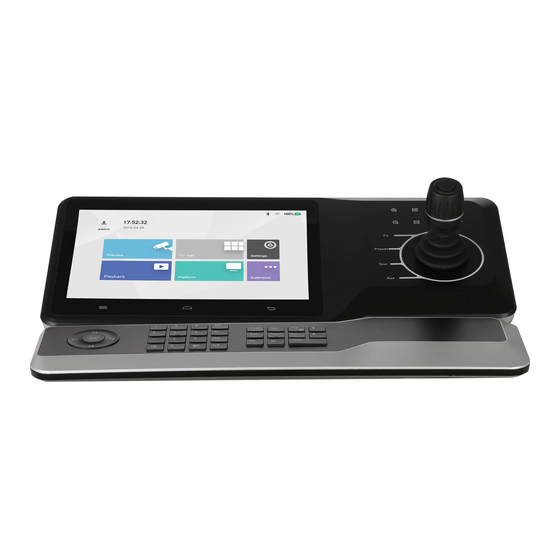
Appearance and Keys of Internet Keyboard Product Appearance Appearance of internet keyboard is shown in Figure 1-1. Please refer to Table 1-1 for details. Figure 1-1 Icon Function Working power indicator light. Power Green light turns on when working power of internet keyboard is normal. -
Page 11: Key Module
Icon Function Touch screen, showing keyboard screen menu. Navigation bar. Homepage. Return. Function key. It is line scanning by default. Preset PTZ control, preset point. Tour PTZ control, tour between points. Auxiliary key. It is pattern by default. Remote control lever, auxiliary menu and function operation. -
Page 12: Port Introduction
Example Function Delete 1 digit from number buffer zone. Press The icon is similar to squares. Reserved. (Camera group) 123+ Drag no. 567 camera into present window. (Camera) 567+ 0+camera means to turn off present video source. Preset 2+preset Call no. 2 preset point. Tour 5+tour Call no. -
Page 13: Side Panel Port
Name Function Alarm input/output port Please refer to Table 1-4 for details. Network port Connect the network. USB3.0 Connect mouse and USB. Microphone Connect microphone. Earphone Connect earphone. Connect devices with HDMI port, such as display HDMI1~HDMI4 screen. Power port Connect power cord to supply power. -
Page 14: Start And Shutdown
Start and Shutdown Start Connect the power in accessories, turn on power on-off key, and start the internet keyboard. The system displays login interface after it is started successfully. Its interface can be operated with touch screen and external mouse. Shutdown Step 1 Shutdown. -
Page 15: Quick Configuration
Quick Configuration Login Interface After starting, the system enters login interface. Step 1 Enter password. Default password of the system is “admin”. Step 2 Click “Login”. After successful login, the system enters main interface. Please modify admin password timely after login. Main Interface Main interface consists of preview, TV wall, playback, platform, settings and extension, as shown in Figure 3-1. -
Page 16: Settings Interface
Name Description Playback Play back videos in local recording device or USB disk. After connecting with the platform, internet keyboard is able to Platform control devices on the platform. There are four modules, including device, general, account and Settings system. Control the devices with direct physical connection with internet Extension keyboard. -
Page 17: Network Settings
bar, quickly return to preview, device, settings, playback, extension and homepage. Network Settings It includes wired network and Wi-Fi settings. 3.4.1 Wired Network Configure IP address and DNS server of internet keyboard, so as to connect with other devices in the networking. Precondition Before setting network parameters, please ensure that the internet keyboard has connected network correctly. -
Page 18: Wi-Fi
Parameter Description It includes multi-address, fault tolerance and load balance. Multi-address: two Ethernet cards are used independently. During network status detection, if one Ethernet card is disconnected, network is deemed to be disconnected. Fault tolerance: two Ethernet cards use one IP address. Only one ... - Page 19 Figure 3-4 Wi-Fi Connection Step 1 Double click Wi-Fi name or signal strength. “Wi-Fi Connection” dialog box will pop out, as shown in Figure 3-5. Step 2 Enter correct password and click “Connect”. In case of successful connection, the connected “Wi-Fi Name” and “Connected” will be displayed at the upper left corner.
-
Page 20: Add Device
Add Device It includes manual adding and auto search. 3.5.1 Enter Device Management Interface In “Settings” interface, click “Device Manage” to enter the interface, as shown in Figure 3-6. Figure 3-6 3.5.2 Manual Add Step 1 Enter “Device Manage” interface and click . -
Page 21: Auto Search
Figure 3-7 Step 2 Set the parameters. Please refer to Table 3-4. Parameter Description Select protocol type. It only supports “Private” at present. Protocol Enter start IP and end IP when one IP segment is added. Start IP and End IP Enter start IP when one IP is added. - Page 22 Figure 3-8 Step 2 Enter IP segment and tick the check box. Step 3 Click “Save”. Auto search results are shown as Figure 3-9. Alternatively, click to view search results. Figure 3-9...
-
Page 23: Preview
Preview Preview local devices, video on wall, PTZ control, snapshot and recording. Enter Preview Interface Click “Preview ” at main interface to enter “Preview” interface, as shown in Figure 4-1. There are five modes, including VGA and HDMI1~HDMI4. Figure 4-1 Icons of Preview Interface Icon Description... -
Page 24: Video On Wall
Icon Description Icon Description Custom split Select screen Smart stream mode Delete Table 4-1 Video on Wall Step 1 At “Preview” interface, select VGA or HDMI1~HDMI4 in pull-down dialog box. Step 2 Select video source in the right, drag it onto TV wall or double click the video source. Quick Video on Wall (Optional) , and a dialog box will pop out, as shown in Figure 4-2. -
Page 25: Ptz Control
Figure 4-3 Maximize and Restore Window Click to maximize and restore the window. Single/4/9/16/Custom Split Click respectively, representing single/4/9/16/custom split. Clear Video Source Step 1 Select a window. Click , to select the focused window. Click again and the icon turns to be , to select all windows within present ... -
Page 26: Snapshot
Snapshot At “Preview” interface, insert a USB disk into Internet keyboard, and click after checking USB disk. Recording At “Preview” interface, insert a USB disk into Internet keyboard, and click after checking USB disk. Snapshot and Recording Settings Step 1 At “Preview” interface, click . - Page 27 Parameter Description Snap settings It supports only 1 snapshot at present. Select resolution. When video resolution﹥ the set resolution, snapshot image Resolution adopts the set resolution. When video resolution﹤ the set resolution, snapshot image adopts actual video resolution. USB storage It is enabled by default.
-
Page 28: Tv Wall
TV Wall Control decoder/matrix/TV wall. Devices can be added only through WEB client. For details, please refer to “5.1 Add TV Wall through Matrix WEB Client” and “5.2 Add TV Wall through Decoder WEB Client”. There are two ways to add TV wall through WEB client: ... -
Page 29: Add Network Signal
5.1.2 Add Network Signal Search or add network signals manually. Step 1 Select “Settings > Signal > Network Signal”. The system displays “Network Signal” interface, as shown in Figure 5-2. Figure 5-2 Step 2 Add network signals. Click “Device Search” to show search results, select the needed device and click ... -
Page 30: Add Tv Wall
Figure 5-3 5.1.4 Add TV Wall Step 1 Select “Settings > Display > TV Wall> TV Wall Config”. The system displays “TV Wall Config” interface, as shown in Figure 5-4. Figure 5-4 Step 2 Click “Add TV Wall” to add it. Add TV Wall through Decoder WEB Client This part takes decoder WEB client as an example. -
Page 31: Enter Decoder Web Login Interface
For more specific configurations, please refer to decoder user’s manual. 5.2.1 Enter Decoder WEB Login Interface Step 1 Enter IP address of decoder at address bar of the browser; press [Enter] key to enter decoder login interface, as shown in Figure 5-5. Figure 5-5 Step 2 Enter username and password. -
Page 32: Edit Decoder Tv Wall
“Add”. Click “Manual Add” to set parameters in the popped out dialog box. 5.2.3 Edit Decoder TV Wall Click merged screen to edit TV wall. Add Device Add TV wall, matrix and decoder device. Please refer to “3.5 Add Device” for details. Video on Wall Step 1 At main interface, click “TV Wall”... -
Page 33: Icons Of Tv Wall Interface
Figure 5-8 Switch Main and Sub-stream Click to switch main and sub-stream. M represents main stream, while S represents sub-stream. Clear Screen Click to clear screen. For other operations of TV wall, please refer to “4.3 Video on Wall”. Icons of TV Wall Interface Please refer to Table 5-1 for introductions to icons. -
Page 34: Ptz Control
Icon Description Icon Description 9-split 16-split Custom split Switch main and sub-stream. M Select screen represents main stream, while S represents sub-stream. Delete Table 5-1 PTZ Control Please refer to “7 PTZ Control”. Add Task Frequently-used operations can be saved as tasks, in order to call them quickly. Step 1 At “TV Wall”... -
Page 35: Configure Tv Wall
Configure TV Wall At “TV Wall” interface, click to enter “TV Wall Config” interface, as shown in Figure 5-10. Figure 5-10 Enable TV Wall to enable TV Wall. Then, “TV Wall” pull-down list in Figure 5-7 will display this TV Click wall. - Page 36 Figure 5-11 Step 2 Enter the name, select line no. and column no., and then click “OK”. Step 3 Drag decoding channels in the right into the screen, so as to bond corresponding relations. Step 4 (Optional) Select two or more screens, click “Merge” to merge them into one screen. Step 5 Click Delete TV Wall Click...
- Page 37 Figure 5-12 Return to TV Wall Interface Click “Return” to return to TV wall interface. Exit TV Wall Interface Click to exit TV wall interface.
-
Page 38: Platform
Platform The internet keyboard can connect with a platform, and thus control devices that are added to the platform. -
Page 39: Ptz Control
PTZ Control Precondition: speed dome owns PTZ function. in “Platform” interface, so PTZ control interface appears in the right, as shown in Click Figure 7-1. Figure 7-1 Parameter Description Step type It consists of fixed step and variable step. By selecting “Fixed”, the step remains unchanged when PTZ ... - Page 40 Use the joystick to control 8 directions of PTZ. Call Enter a number in the input box, such as “1”. Click “Preset” to call the preset point 1. It will be called successfully under the precondition that preset point 1 exists. Call methods of scan, tour and pattern are the same as that of preset point.
- Page 41 Settings of Pattern Step 1 Enter pattern no. in the dialog box of pattern no.. Step 2 Click “Start Pattern” to carry out operations of zoom, focus, iris or direction. Step 3 Click “Stop Pattern” to complete the settings of one pattern route. Settings of Scan Turn the camera to left margin with the joystick or direction button;...
- Page 42 SD Menu Figure 7-4 Auxiliary Function Figure 7-5 Auxiliary function includes single light, multi-light and wiper. Light mode includes manual, SmartIR and zoom ratio first. Light strength: light strength can be set. Light angle: light angle can be set.
-
Page 43: Settings
Settings It consists of four parts, namely, device, general, account and system. Device Management 8.1.1 Add Device Please refer to “3.5 Add Device”. 8.1.2 Input Channel Display input no., channel no., name, device, IP address and protocol of all channels. Meanwhile, modify input channel no.. -
Page 44: General Settings
General Settings 8.2.1 Wired Network Please refer to “3.4.1 Wired Network” for details. 8.2.2 Wi-Fi Please refer to “3.4.2 Wi-Fi” for details. 8.2.3 Bluetooth Default Bluetooth name of internet keyboard is “KEYBOARD”. Step 1 At “General” interface, click “Bluetooth” tab to enter “Bluetooth” interface. Step 2 Click to enable Bluetooth. -
Page 45: General
Figure 8-3 Step 2 Set the parameters. Please refer to Table 8-1 for details. Parameter Description Address In case of serial port control, identify devices according to the address. Value ranges from 0 to 255. Baud rate Baud rate ranges from 1200 to 115200. There are 8 levels available. Data bit Select data bit, including 5, 6, 7 and 8. -
Page 46: Hardware
Figure 8-4 Step 2 Set the parameters. Please refer to Table 8-1 for details. Parameter Description Name Set internet keyboard name. Language Select language. Date Set date. Time Set time. Format Set time format, including 24-hour and 12-hour. Set date separator, including “.”, “-” and “/”. When it takes effect, system Separator time is displayed as “2017.08.08”, “2016-08-08”... -
Page 47: Account
Figure 8-5 Step 2 Set the parameters. Please refer to Table 8-2 for details. Parameter Description Volume adjust Adjust the volume. Keyboard lock After keyboard is locked, log in the device to enter it again. Screen off Screen off time can be max. 60 minutes. Table 8-3 Step 3 Click “Save”. -
Page 48: System
System 8.4.1 Version Upgrade Upgrade the device with USB disk. Step 1 At “System” interface, click “Upgrade” tab to enter “Upgrade” interface, as shown in Figure 8-7. Figure 8-7 Step 2 Insert USB disk into the internet keyboard, and click “USB Check”. Step 3 Click “Choose Files”... - Page 49 Figure 8-8 Insert USB disk into the internet keyboard, and click “USB Check”. Detect all Step 2 connected USB and capacity. Step 3 Import or export configurations. Import config: import config info in USB disk into the internet keyboard. Export config: export config info in the present keyboard to USB disk.
-
Page 50: Playback
Playback Play back existing records. Step 1 At main interface, click “Playback” tab to enter “Playback” interface. Step 2 Select target device and channel. Step 3 Set the start time and end time. Step 4 Click “Search”. Display search results in the list, as shown in Figure 9-1. Figure 9-1 Step 5 Select one search result and click “Playback”, as shown in Figure 9-2. - Page 51 Figure 9-2 Step 6 Click to download the record to USB disk. Records in USB disk can be played back.
-
Page 52: Extension
Extension Control the devices with direct physical connection with internet keyboard. At present, it only supports to control speed dome with 485 port. Step 1 At main interface, click “Extension” to enter “Analog Keyboard” interface, as shown in Figure 10-1. Figure 10-1 Step 2 Set the parameters. -
Page 53: Appendix 1 Technical Parameters
Appendix 1 Technical Parameters Parameter Description LCD screen 10.1 inch TFT LCD screen, 1280×800 resolution Touch screen 10.1 inch capacitance screen, 1280×800 resolution Joystick 4D joystick Video port 1 LCD screen and 4 HDMI ports. There are 5 output ports in total. [Stream type] Support H.265, H.264, H264H, H264B, MJPEG, SVAC, SmartH.264 and non-standard stream.
Need help?
Do you have a question about the NKB5000 Series and is the answer not in the manual?
Questions and answers
how do you restart the nkb 5000 joystick when it goes to sleep