
Related Manuals for Sentec SDM


Summary of Contents for Sentec SDM
- Page 1 For the SenTec Digital Monitoring System (Software Version SMB V08.02; MPB V06.02)
- Page 2 SenTec AG are used, if the warranty seal on the lower side of the monitor is broken, or if instrument repairs are not carried out by SenTec authorized service personnel.
-
Page 3: Table Of Contents
Contents Contents Figures Tables Abbreviations INTRODUCTION Related Documents Safety Information THE SENTEC DIGITAL MONITORING SYSTEM (SDMS) Components The SenTec Digital Monitor (SDM) MAINTENANCE/SAFETY & FUNCTIONALITY TESTS SenTec TC Sensors SenTec Digital Monitor Docking Station Digital Sensor Adapter Cable Opening the Membrane Changer... - Page 4 Cutaneous carbon dioxide partial pressure (i.e. the CO2 partial pressure at the skin surface) PCO2 Used to display/label tcPCO2 on the SDM and – unless explicitely stated otherwise – throughout this manual PcO2 Cutaneous oxygen partial pressure (i.e. the O2 partial pressure at the skin surface)
- Page 5 Pulsation Index Used to display/label tcPO2 on the SDM and – unless explicitely stated otherwise - throughout this manual POST Power-On Self-Test Responsible Organization Pulse rate Relative Heating Power Remote monitoring interrupted SaO2 Arterial oxygen saturation SenTec Digital Monitor SDMS...
-
Page 7: Introduction
SenTec authorized technicians only; repair procedures that do not require opening the cover of the SDM intended see section for qualified personnel only (... -
Page 8: Related Documents
1 Introduction Related Documents To perform service or repairs you must know how to operate the SDMS. The SDMS consists of the SenTec Digital Monitor (SDM), sensors and accessories. Refer to the following Manuals and Directions for Use: Table 1... - Page 9 Instruction Manual for the Note: The and the SDMS in all available languages can also be downloaded from SenTec’s Webpage (https://www.sentec.com/education/customer-portal). Information / Instructions about the Digital Sensor Adapter Cable, the Instruction Manual for Contact Gel and the Service Gas are provided in the...
-
Page 10: Safety Information
Technical Manual for the Carefully read all safety information in this Manual and in the SDM (HB-005752) before operating the device or performing service/repairs. HB-005615-j... - Page 11 WARNING: To ensure patient safety, do not place the SDM in any position that might cause it to fall on the patient. WARNING: Do not lift the SDM by the sensor cable or the AC power cord because they could disconnect from the SDM, causing the SDM to fall on the patient.
- Page 12 Ensure that power and protective ground lines are connected correctly. If case of doubt (e.g. as this may be the case during home use of the SDM) disconnect the SDM from the outlet and use the battery power during patient monitoring.
- Page 13 SDM and accessory equipment. In certain cases it may be required that the SDM and the accessory equipment must be connected to a grounded AC outlet. In case of doubt consult qualified technicians.
- Page 14 WARNING: The Roll Stand, model RS_SDM, is intended for use with the SDM only or in combination with the Cable Cleat, model CC_SDM, and the SDM. The mounting plates are intended for use with the SenTec Digital Monitor (SDM) only. Do not use the accessories for devices from other manufacturers than SenTec together with SenTec Digital Monitoring System (SDMS).
- Page 15 1 Introduction CAUTION: To ensure accurate performance and prevent device failure, do not subject the SDM to heavy moisture, such as direct exposure to rain. Such exposure may cause inaccurate performance or device failure. If the SDM becomes wet accidentally, it should be removed from AC power, wiped dry externally, allowed to dry thoroughly, and inspected by qualified service personnel before further use.
- Page 16 WARNING: Chemicals from a broken LCD display panel are toxic when ingested. Use caution when handling a SDM with a broken display panel. Electronic components may content toxic chemicals. Do not ingest chemicals from a broken electronic component.
-
Page 17: The Sentec Digital Monitoring System (Sdms)
(to connect VS-A/P/N or OV-A/P/N to SDM; YYY=150, AC-YYY 250, 750 cm) EC-MI Ear Clip (to apply SenTec TC Sensors at earlobe of patients with mature/ intact skin) Multi-Site Attachment Ring MAR-MI (to apply SenTec TC Sensors to patients with MAR-MI mature/ intact skin) -
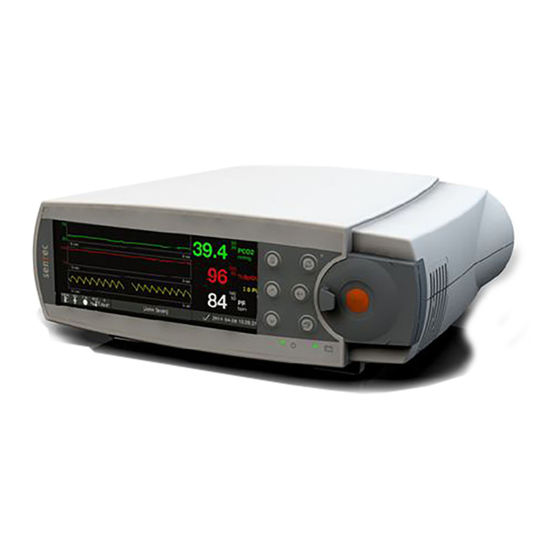
Page 18: The Sentec Digital Monitor (Sdm)
Front Panel of the SDM Note: SDMs with firmware version SMB SW-V08.00/ MPB SW-V06.00 are available with and without activated PO2-option. If the PO2-option is activated the colored dot in the Docking Station Door of the respective SDM will be blue, otherwise orange. HB-005615-j... -
Page 19: Figure 2 Rear Panel Of The Sdm
Otherwise you risk damage or malfunction of the SDM. CAUTION: Ensure that the fan of the SDM is clear of any obstructions and that the SDM is located in a well-ventilated dust-free atmosphere. Failure to do so could cause damage or malfunction of the SDM. -
Page 20: Maintenance/Safety & Functionality Tests
3 Maintenance/Safety & Functionality Tests At normal use there is no internal adjustment or new calibration of the SDM required. However, to guarantee continuous performance, reliability and safety of the SDMS routine checks and maintenance procedures (including cleaning/disinfection) as well as safety checks should be performed regularly. -
Page 21: Sentec Tc Sensors
Check presence/legibility of the serial number (label on the plug of the sensor cable). If the serial number label is not present / legible then connect the sensor to a SDM, switch the monitor on, read the sensor’s serial number in the menu "System information”, and write it on the plug of the sensor cable. -
Page 22: Figure 3 Removal Of The Membrane From The Tc Sensor
(i.e. by observing the temperature indicator located in the Status Bar of the SDM`s display). Verify that the red sensor LED switches off, a low priority alarm starts to sound and that the message "Temp. limiter active" (or ‘Sensor problem 38’, ‘Sensor problem 42’) displays. -
Page 23: Figure 4 Top View Of The V-Sign™ Sensor
OxiVenT™ Sensor. If the ring around the pH-glass is broken, parts of it are missing, the brown color is lost, or the ring has a metallic luster, then replace the sensor with a new SenTec TC Sensor. The sensor has an intact brown ring around the The ring around the pH-glass is intact but has a pH-glass. -
Page 24: Figure 5 Inspection After Remembraning The Sensor
‘Sensor problem 72’ (PO2 sensitivity) will only reset, if the test was successful. Note: If a V-Sign™ Sensor is connected to the SDM the function ‘Sensitivity Test’ will test the sensor`s PCO2 sensitivity. If an OxiVenT™ Sensor is connected to the SDM the function ‘Sensitivity Test’... - Page 25 If the ‘Sensitivity Test’ passed, the Status Message ‘Ready for use’ appears. Calibration Duration: The calibration duration should be shorter than 14 minutes. If the calibration duration is longer than 14 minutes `PCO2 slow´or ‘Sensor problem 11’ or ‘Sensor problem 71’ is displayed. Refer to troubleshooting P0304. SenTec Digital Monitoring System...
- Page 26 Note: For a V-Sign™ Sensor only the PCO2 Slope Test must be performed. For an OxiVenT™ Sensor both, PCO2 and PO2 Slope Test, must be performed. Note: The Slope Test can also be performed using a second SDM instead of a Sensor Tester Unit. Also, a single SDM can be used (requiring changing gas bottles after each step).
- Page 27 6 minutes (this is to ensure that no gas leak is present in the Docking Station of the SenTec Sensor Tester). Note: If you are using an SDM for the Slope Test and in case of an OxiVenT™ Sensor the message `Sensor Problem 73´ appears on the SDM at this stage. This is an expected behavior of the sensor.
-
Page 28: Figure 6 Examples: Pco2 And Po2 Slope Test
3 Maintenance/Safety & Functionality Tests Figure 6 Examples: PCO2 and PO2 Slope Test HB-005615-j... - Page 29 41.4 23.8 24.7 26.3 41.7 24.0 24.9 26.5 42.0 24.1 25.1 26.7 42.3 24.3 25.3 26.9 42.6 24.5 25.5 27.1 42.9 24.7 25.7 27.3 43.2 24.9 25.9 27.5 43.5 25.1 26.1 27.7 43.8 25.2 26.3 27.9 SenTec Digital Monitoring System...
- Page 30 3 Maintenance/Safety & Functionality Tests Slope Test Control Table CO2 – in kPa (after 5% and 30% CO2 calibration) Pcal = value after calibration with 8% CO2. Table is only valid for sensor temp. of 42°C. Pcal 5_min 5_ideal 5_max 30_min 30_ideal 30_max...
- Page 31 21_max 72.0 72.6 73.2 73.8 74.4 75.0 75.6 76.2 76.8 77.4 78.0 78.6 79.2 79.8 80.4 81.0 81.6 82.2 82.8 83.4 84.0 84.6 85.2 85.8 86.4 87.0 87.6 88.2 88.8 89.4 90.0 90.6 91.2 91.8 92.4 SenTec Digital Monitoring System...
- Page 32 3 Maintenance/Safety & Functionality Tests Slope Test Control Table PO2 – in kPa (after 6% and 21% O2 calibration) Pcal = value after calibration with 12% O2 Table is only valid for sensor temp. of 42°C. Pcal 6_min 6_ideal 6_max 21_min 21_ideal 21_max...
- Page 33 In case of an OxiVenT™ Sensor additionally test PO2 function: Power-cycle the SDM (i.e. switch it off and on again). Then calibrate the OxiVenT™ Sensor. After successful calibration the PO2 function test can be performed as follows: Open the Docking Station Door in order to expose the sensor to ambient air.
- Page 34 3 Maintenance/Safety & Functionality Tests PO2 Function Test Control Table PO2 – in mmHg and kPa PO2 ranges are valid for ambient temperatures between 18°C and 28°C and relative humidity between 30% r.H. and 60% r.H! Patm ambient_ ambient ambient_ Patm ambient_ ambient...
- Page 35 Nellcor). The SpO2 and PR reading should be within ± 3% SpO2 and ± 3 bpm, respectively. section 4.2.1 “Troubleshooting SpO2 / PR If this requirement is not met refer to monitoring” to further evaluate the problem. SenTec Digital Monitoring System...
-
Page 36: Sentec Digital Monitor
"Instructions for Shipment”. send back the monitor according to For SenTec authorized service technicians only: If the above requirements for the front panel are not fulfilled then replace the SDM Case, upper part according Repair Manual for the SDMS to the (HB-005755). -
Page 37: Figure 7 Connections For The High Potential Test, Ap
High voltage can lead to injury or death. The sensor is an applied part of Type BF. The interface ports of the SDM meet the same requirements as the sensor port and are tested in an analogous manner. -
Page 38: Figure 8 Connections For The High Potential Test, Pc
3.2.4.2 Safety test according to IEC 60601-1 Safety analyzer for tests according to IEC 60601-1 (e.g. Tools 601PROXL International Safety Analyzer from BIO-TEK) If the required equipment is not available, send the SDM to your local SenTec representative for testing. HB-005615-j... - Page 39 High voltage can lead to injury or death. The sensor is an applied part of Type BF. The interface ports of the SDM meet the same requirements as the sensor port and are tested in an analogous manner.
-
Page 40: Figure 9 Connections For The Safety Test
3.2.5 POST After turning on the SDM performs a power-on self-test (POST), which tests the SDM’s circuitry and functions (internal test). The display, as well as the visual and audible indicators (i.e. LED’s and speaker) are activated. The result of the POST is indicated... - Page 41 Repair Manual for the SDMS to the (HB-005755). 3.2.7 Clock Settings Verify that the clock settings are correct. If necessary, adjust the clock in the SDM Menu "System Settings Date / Time". Power cycle the SDM and control the clock settings. section 4.2.4 "SDM specific...
- Page 42 Display/LED’s Check indicator LED’s and the display for defects: 1. Connect the SDM to AC power. Switch the SDM OFF and ON again: During the POST, the Alarm Mute Indicator (yellow LED) and the ON/OFF Indicator (green LED) are activated. The AC Power/Battery Indicator LED is lit yellow (battery...
- Page 43 The fan should briefly activate during POST. The fan should rotate freely and without causing unusual noises. The fan should rotate without obstruction when you blow into the fan slits on the rear panel of the SDM (note that the fan needs to be off during this test).
- Page 44 "SenTecLink" (proceed as described in the Connect one end of a serial cable to the serial data port (RS-232) of the SDM and connect the other end of the cable to a serial port of your PC. If your computer has no serial port but USB-ports an USB232 Converter Cable can be used.
- Page 45 Close ‘Profiles / SDM settings’ window. On the SDM: navigate to menu Interfaces LAN interface. If in DHCP mode you should now see the IP address assigned by the DHCP server.
- Page 46 6 hours of monitoring time (if SLEEP MODE = OFF) and approximately 13 hours (if SLEEP MODE = ON). In case of a SDM with a display with ‘LED Backlight’ a new, fully charged battery provides approximately 11 hours of monitoring time (if SLEEP MODE = OFF) and approximately 16 hours (if SLEEP MODE = ON).
-
Page 47: Docking Station
Insert the sensor in the Docking Station and verify that the "100% gas icon" displays in the status bar. Remove the gas bottle from the SDM and verify that the yellow "0% gas icon" displays in the status bar. section 4.2.4... -
Page 48: Digital Sensor Adapter Cable
3.4.1 Cleaning and Disinfection Clean or disinfect the `Digital Adapter Cable´ as often as required per institutional ordinances (recommended weekly). For cleaning and disinfection instructions refer to Technical Manual for the SDM (HB-005752). 3.4.2 Visual Inspection Check the Digital Sensor Adapter Cable for damages of the isolation. Check the Digital Sensor Adapter Cable connectors for damages. -
Page 49: Opening The Membrane Changer
WARNING: Wear protective goggles while breaking out the 6 latches. CAUTION: This procedure will irreversibly destroy the Membrane Changer, but not harm the sensor if executed with care. latches removed latches Figure 11 Opening the Membrane Changer SenTec Digital Monitoring System... -
Page 50: Troubleshooting
"Repairs" Repairs (without having to open the SDM cover) are described in Repairs that require opening the cover of the SDM are to be performed by SenTec Repair authorized service technicians only and are described in detail within the... -
Page 51: Table 5 Example Of A Troubleshooting Procedure
P0XXX Wrong/instable Verify that the barometric pressure reading of the barometric pressure SDM is stable during calibration and does not (operator) during calibration deviate from a known calibrated reference PCO2 barometer by more than 5 mmHg (0.7 kPa). -
Page 52: Troubleshooting List
Verify proper operation of the blood gas analyzer. Periodically compare the blood gas analyzer’s barometric pressure against a known calibrated reference barometer. Note: This section only is applicable for SenTec TC Sensors with PCO2 and/ or PO2 enabled. HB-005615-j... -
Page 53: Table 6 Troubleshooting Pco2/ Po2 Monitoring
Note: Also refer to Status Messages ‘Check sensor application’, ‘PCO2 stabilizing’, ‘PO2 stabilizing’, or ‘PCO2/ PO2 stabilizing’ (refer to Technical Manual for the SDM Sensor applied to a Apply sensor to a recommended measurement site measurement site with an appropriate Sensor that is inadequate / Attachment Accessory. - Page 54 [min]: on’ the “Ready for use” screen and on Technical the “Calibration” screen (see Manual for the SDM Wrong / expired Verify that SenTec Service Gas is used. If calibration gas was expired replace with a new gas bottle! used during last calibration...
- Page 55 4 Troubleshooting Problem Possible Cause(s) Recommended corrective action(s) PO2 Measurement Shield SenTec TC Sensor from strong is influenced by ambient light. high ambient light Note: Refer to Status Message ‘High ambient levels light’ (with Status Code ‘SA’). Clean/Inspect the sensor as described in section 3.1.7...
- Page 56 (potential skin burns). Carefully read the section “Sensor Technical Temperature & Site Timer” in the Manual for the SDM Remember: In most patients PO2 monitoring requires higher temperatures than PCO2 monitoring. In newborns, PO2 correlates with PaO2 almost in a one to one relationship at a sensor temperature of 43 to 44 °C, whereby the accuracy of PO2...
- Page 57 Station. PCO2 and or PO2 Refer to P0305 sensitivity of the sensor low/ deteriorated PO2 Measurement Shield SenTec TC Sensor from strong is influenced by ambient light. high ambient light Note: Refer to Status Message ‘High ambient levels Technical light’ (with Status Code ‘SA’) (see...
- Page 58 4 Troubleshooting Problem Possible Cause(s) Recommended corrective action(s) Sensor loosely Refer to identical ‘Possible Cause’ in P0100 P0103 attached to patient for recommended corrective action(s) PCO2 and/ or (air between sensor PO2 suddenly and skin; no change / contact liquid) change very fast (‘TC Adhesive pad of Ear...
-
Page 59: Table 7 Troubleshooting Spo2/ Pr Monitoring
4 Troubleshooting 4.2.2 Troubleshooting SpO2 / PR monitoring Note: This section is applicable for SenTec TC Sensors (if SpO2 / PR are enabled) and for SenTec’s oximetry sensors. Table 7 Troubleshooting SpO2/ PR Monitoring Problem Possible Cause(s) Recommended action(s) Venous pooling Limitation of the method. -
Page 60: Table 8 Sensor Specific Troubleshooting
TC Sensor and try again (if necessary message Cable’ defective permute and try on a different SDM). ‘Connect In case of damage of the SenTec TC Sensor sensor’ replace it by original replacement parts. displays In case of damage of the ‘Digital Sensor Adapter Cable’... - Page 61 ‘Sensor trapped air or dry electrolyte under the problem 10’ membrane. Wrong / expired Verify that SenTec Service Gas is used. calibration gas was If expired replace with a new gas bottle! used during last calibration Substantial gas leak...
- Page 62 Clean the sensor as described in “Cleaning / Inspecting without Membrane” Then calibrate the sensor. SenTec TC Sensor If the problem persists the SenTec TC Sensor defective is defect. Replace it with a new one. Calibration Module Replace the Calibration Module according to...
- Page 63 4 Troubleshooting Problem Possible Cause(s) Recommended action(s) SenTec TC Sensor If the problem persists the SenTec TC Sensor defective is defect. Replace it with a new one. Membrane related Change the membrane: P0305 (defective or dried PCO2 if it is damaged or missing, has a loose fit,...
- Page 64 SDM not activated activated and PO2 is enabled in the menu of OxiVenT™ or – if activated - the SDM. After doing so, verify that the off- Sensor PO2 not enabled in centered white spot is illuminated in green connected to the menu of the cyan color.
-
Page 65: Figure 14 Replacement, Main Fuses
The sensor can still be used for monitoring of the other parameters but PO2. Replace OxiVenT™ Sensor if you wish to continue monitoring PO2. Note: In this case the SDM should display the message ‘Sensor problem 73’ (see Technical Manual for the SDM 4.2.4... - Page 66 Recommended action(s) Repair SMBM Replace SMBM according to the Manual for the SDMS (Motherboard) defective To be performed by SenTec authorized service technicians only. SDM switched off Switch on SDM. P0401 Display is If problem persists contact qualified service dark, AC personnel.
- Page 67 To be performed by SenTec authorized service technicians only. SDM in Sleep Mode Press any button. P0403/P0504 Display is If the problem persists switch the SDM off dark, ON / and on again. OFF indicator If problem persists contact qualified service is illuminated personnel.
- Page 68 Manual for the SDMS (Motherboard) defective To be performed by SenTec authorized service technicians only. POST failed Write down the Error code, switch the SDM P0405 off and on again. POST screen does not If problem persists contact qualified service disappear personnel.
- Page 69 Barometer chip Verify that the barometric pressure reading of P0408 defective the SDM is stable during calibration and does Wrong / not deviate from a known calibrated reference unstable barometer by more than 3 mmHg (0.4 kPa).
- Page 70 Contact SenTec authorized service personnel. Repair Fan polluted Clean case and Fan according to the Manual for the SDMS To be performed by SenTec authorized service technicians only. Repair Manual Fan defective Replace Fan according to the for the SDMS To be performed by SenTec authorized service technicians only.
- Page 71 Possible Cause(s) Recommended action(s) Repair SMBM Replace SMBM according to the Manual for the SDMS (Motherboard) defective To be performed by SenTec authorized service technicians only. Auditory alarm Reactivate auditory alarm signals (if P0411 signals are PAUSED necessary) No sound...
- Page 72 AC Power Replace AC Power Connector according to the Repair Manual for the SDMS possible to Connector defective connect the AC power To be performed by SenTec authorized service technicians only. cord in the SDM AC power connector SDM defective Contact SenTec authorized service personnel.
- Page 73 Repair SMBM Replace SMBM according to the Manual for the SDMS (Motherboard) defective To be performed by SenTec authorized service technicians only. Auditory alarm is Auditory alarm signals can be muted for 1 P0416 muted minute, 2 minutes or permanently with the No alarm on Alarm Mute Button.
- Page 74 Possible Cause(s) Recommended action(s) Gas level indicator Repeat the test with the same sensor P0418 shows wrong connected to the same SDM using the Gas Level results Docking Station of another SDM (Both SDMs Indicator need to be switched on).
-
Page 75: Table 10 Docking Station Specific Troubleshooting
To be performed by SenTec authorized service technicians only Contaminations P0501 Clean Docking Station and SenTec TC Sensor (e.g. gel residues) and then insert the sensor into the Docking Message disturb the gas flow Station. ‘Docking Station Fault’... - Page 76 Foreign body in the Switch off the SDM, disconnect it from the properly slot for the Service mains supply and remove the foreign body Gas bottle from the slot on the rear panel of the SDM. HB-005615-j...
- Page 77 Contact SenTec authorized service personnel. Docking Station Replace Docking Station Module according to Repair Manual for the SDMS Module defective To be performed by SenTec authorized service technicians only Low pressure side Verify whether DP01 status code is flagged. P0504...
- Page 78 4 Troubleshooting Problem Possible Cause(s) Recommended action(s) Refer to P0308 P0505 Sensor calibration does not start, Sensor LED is illuminated Refer to P0418 P0506 Gas Level Indicator shows wrong indication HB-005615-j...
-
Page 79: Repairs Of The Sdm
5 Repairs of the SDM 5 Repairs of the SDM Repairs described in this chapter do not require opening the SDM`s cover and shall be carried out by qualified service personnel only. Repairs that require opening the cover of the SDM are to be performed by SenTec authorized service technicians only (i.e. -
Page 80: Prior To Repair
5 Repairs of the SDM WARNING: Before replacing fuses of the SDM, disconnect the device from the AC power. CAUTION: Follow ESD (Electrostatic discharge) precautions when working with the SDM, especially when disassembling and reassembling the SDM and when handling any of the components. -
Page 81: Replacement, Silicon Foot
Replacement, Main Fuses 3. Replace the defective fuses with time delay, high breaking capacity fuses, by fuses with rated current as specified on the SDM rear panel (see section 8.2 “Testing Accessories and Spare Parts”) 4. Reinsert the holder into the AC Power Connector. -
Page 82: Replacement, Docking Station Door
5 Repairs of the SDM Replacement, Docking Station Door section "Prior to Repair" Follow the procedure described in see Figure 15 Open the Docking Station Door (to an angle of approximately 120° ( Docking Station Door Insertion Lift the mounting link for the hinge and remove the Docking Station Door by pulling it out and pressing it down at the same time. -
Page 83: Replacement, Docking Station Gasket
5 Repairs of the SDM Replacement, Docking Station Gasket section "Prior to Repair" Follow the procedure described in Open the Docking Station door. Remove the defective gasket using tweezers. Take care not to damage the lining groove. Clean the lining groove using a cotton swap soaked with 70% isopropanol, allow to dry. -
Page 84: Figure 17 Positioning Of The Docking Station Gasket
5 Repairs of the SDM Figure 17 Positioning of the Docking Station Gasket HB-005615-j... -
Page 85: Software Updates
6 Software Updates 6 Software Updates The field-upgradable software of the SDM consists of two items: SMBC – Controller Board software (User Interface, Memory and Interface management) MPB – Multiparameterboard software (Signal Analysis Algorithm) The SMBC and MPB software can be updated by trained and authorized personnel by flashing a new version in the flash memory of the existing boards (note: detailed instructions are included in separate documents). -
Page 86: Disposal
Note: By recycling materials or other forms of utilizing old devices, you are making an important contribution to protecting our environment. SenTec Digital Monitor Return the SDM to your local SenTec representative or dispose it according to local regulations. Cables Dispose the cables according to local regulations. -
Page 87: Appendix
HB-005638 Testing Accessories and Spare Parts WARNING: Use only testing accessories and spare parts supplied or recommended by SenTec AG. Use of other than supplied or recommended parts may result in physical injury, inaccurate measurement and/or damage to the device. -
Page 88: Sdms Maintenance Checklist
The three interface connectors - serial data port, Multipurpose I/O port (analog outputs, nurse call), LAN port - of the SDM are not separated from each other. If at a time accessory equipment is connected... -
Page 89: Figure 18 Sensor Connection Port
1 - 3 (reserved) Signal Ground Received Data (RX, from Sensor) Transmitted Data (TX, to Sensor) 7 - 9 (reserved) 5 V, for sensor supply only Supply Ground 3.3 V, for sensor supply only 13 - 14 (reserved) SenTec Digital Monitoring System... -
Page 90: Figure 19 Serial Data Port (Rs-232)
The Serial Data Port (RS-232) Figure 19 Serial Data Port (RS-232) Table 12 Pin Assignment, Serial Data Port (RS-232) Pin(s) Signal (reserved) Transmitted Data (TX, from SDM) Received Data (RX, to SDM) (reserved) Signal Ground 6 – 9 (reserved) 8.9.3 Multipurpose I/O Port... -
Page 91: Table 13 Pin Assignment, Multipurpose I/O Port
(reserved) 20 - 21 Ground 3.3 V, max. 15 mA Ground Common lead for Nurse Call relays 1 + 2 closes upon SDM (24 + 25) Nurse Call relay 1 open, close audible alarm opens upon SDM (24 + 26) -
Page 92: Technical Specifications
The LAN port of the SDM is used to communicate with external computer based data collection systems. The LAN port is located on the rear panel of the SDM. The LAN port is a standard 10Base-T Ethernet connector. Use Category 3 (Cat3) or preferably Category 5 (Cat5) Ethernet cables for connection of the monitor to a network hub or switch. - Page 93 8 Appendix HB-005615-j Date of release: 02/2019 SenTec Digital Monitoring System...
Need help?
Do you have a question about the SDM and is the answer not in the manual?
Questions and answers