Table of Contents
Advertisement
Quick Links
Operation, Installation and Service Manual
Original Documentation / Keep for Future Reference
NAVIGAT 100
Digital Gyrocompass Systems
Type 5026-AA, Stock No. 073518
05026-0128-01
056373/D, 19 Feb 2019
Northrop Grumman Sperry Marine B.V. (Representative Office)
Woltmanstr. 19 • D-20097 • Hamburg, Germany
Tel.: +49-40-299 00-0 • Fax: +49-40-299 00-146 • E-mail: service.eu@sperry.ngc.com
Advertisement
Table of Contents

Related Manuals for Sperry Marine NAVIGAT 100


Summary of Contents for Sperry Marine NAVIGAT 100
- Page 1 Original Documentation / Keep for Future Reference NAVIGAT 100 Digital Gyrocompass Systems Type 5026-AA, Stock No. 073518 05026-0128-01 056373/D, 19 Feb 2019 Northrop Grumman Sperry Marine B.V. (Representative Office) Woltmanstr. 19 • D-20097 • Hamburg, Germany Tel.: +49-40-299 00-0 • Fax: +49-40-299 00-146 • E-mail: service.eu@sperry.ngc.com...
- Page 2 This document and the information herein is and remains the intellectual property of Northrop Grumman Sperry Marine B.V. [NGSM BV] and its associate companies and may not be copied, reproduced or translated without the express permission of NGSM BV. A limited license is grant- ed for the user to reproduce this documentation for his own internal use, but not for distribution to third parties.
-
Page 3: Table Of Contents
Menu Timeout Function ................2-4 External Control Devices ................2-4 Power-up ....................2-5 NAVIGAT 100 Restart .................. 2-7 Selecting the Active Heading Source............2-8 Adjusting the Display Brightness ............2-9 Adjusting the Display Contrast.............. 2-10 NAVIGAT 100 CDU Initialisation ............2-10... - Page 4 Alarm Displays..................... 3-4 Warning Displays..................3-8 Alerts / check................... 3-11 Chapter 4: Scheduled Maintenance Maintenance of the NAVIGAT 100............4-1 Cleaning of Compass Housing ..............4-1 Cleaning of Air Inlet Grill................4-1 Gyrosphere Maintenance ................. 4-2 18-Month Maintenance ................4-2 Five-Year Maintenance ................
- Page 5 NAVIGAT 100 056373/D Chapter 6: System Installation Installation Recommendations..............6-1 Place of Installation ..................6-1 Ventilation / Temperature ................6-1 Electromagnetic Interference..............6-1 Vibration ...................... 6-2 Mechanical Installation ................6-3 Gyrosphere Container Mod 10/4 Preliminaries ........... 6-4 Installing the Compass Housing ..............6-4 Electrical Installation ................
- Page 6 056373/D NAVIGAT 100 Chapter 8: Troubleshooting Troubleshooting Instructions ..............8-1 Location of Parts on the NAVIGAT 100 Mainboard ........ 8-2 Terminal Boards................... 8-3 Connectors ....................8-4 Diagnostic LEDs ..................8-4 Chapter 9: Corrective Maintenance NAVIGAT 100 Software Update..............9-2 Software Update Procedure ................ 9-4 Chapter 10: NAVIGAT 100 Spare Parts 10.1...
-
Page 7: Safety Instructions
NAVIGAT 100 056373/D Safety Instructions Safety Notice Conventions The following safety notice conventions are followed throughout this manual: A Danger notice begins with the named type of DANGER danger and contains an operating or mainte- nance procedure, practice, condition, statement, etc., which, if not strictly observed, will result in... -
Page 8: General Safety Information For The Operator
Power up the system at least three hours before leaving harbour. Power down the system during long docking periods only. Make sure that the NAVIGAT 100 has settled before using its heading as the reference for heading control systems, RADAR, ECDIS, etc. - Page 9 Risk of Deviation Loss of or invalid speed and/or position input data will flaw the north speed error correction of the NAVIGAT 100 and cause deviation. Always have in mind, that the north speed error correction needs valid speed and position input for reliable heading functionality and long time stable operation of the CompassNet system.
- Page 10 NEVER shut down the NAVIGAT 100, while the vessel is navigating. A shut down of the NAVIGAT 100 system for good reason is only possible when the ship is NOT navigating.
- Page 11 Never use mercury with the gyrosphere type 3 and the gyrosphere con- tainer mod. 10/3. In case of usage of mercury by mistake, the contaminated equipment must not be used and all safety instructions of the Sperry Marine Mer- cury Handling Procedure 026150-0000-000 must be followed accordingly. CAUTION Risk of defective gyrosphere caused by “GYRO FAILURE”...
- Page 12 056373/D NAVIGAT 100 CAUTION Risk of damage through unauthorized service Only authorized service personnel is allowed to remove the gyrosphere from the gyrosphere container. Always keep to the mandatory safety requirements and the correct ser- vice work procedure to remove the gyrosphere from the gyrosphere con- tainer.
- Page 13 (CAM) according to specified standards ISO 16328 and IEC 61924-2. Note All alerts of the NAVIGAT 100 gyrocompass system are category B alerts according to IEC 61924-2. Note For installation and service procedures of the gyrosphere and gyro-...
-
Page 14: General Safety Information For Service Personnel
Life danger through electrical shock When the NAVIGAT 100 compass is energized, the gyrosphere operating voltage of 100 VAC @ 333 Hz is present on the NAVIGAT 100 mainboard, the gyrosphere supply lines, and across the gyrosphere contacts. Make sure that the main and backup power supplies of the compass are... - Page 15 NAVIGAT 100 056373/D WARNING Risk of Injury Unprotected contact with loose (unpacked) supporting fluid is consid- ered to be harmful to personnel. Never allow unprotected contact of loose (unpacked) supporting fluid to eye or skin. Always use safety gloves and safety glasses as personal protective equipment (PPE) when handling with loose (unpacked) supporting fluid.
- Page 16 Sperry Marine requires to install the main power and a backup power supply for the NAVIGAT 100 through the strip-wound core inside the compass housing to meet EMC values. Never install the power supplies of the NAVIGAT 100 without using the strip-wound core. CAUTION...
- Page 17 - the steering magnetic compass is exchanged or newly adjusted, - the magnetic compass heading sensor is exchanged and, - when the NAVIGAT 100 mainboard is exchanged, in case a fluxgate sen- sor is used. Never use a true heading source, e.g. a gyrocompass, as the calibration reference.
- Page 18 (CAM) according to specified standards ISO 16328 and IEC 61924-2. Note All alerts of the NAVIGAT 100 gyrocompass system are category B alerts according to IEC 61924-2. Note For installation and service procedures of the gyrosphere and gyro-...
-
Page 19: Chapter 1: Introduction
(ROT) data for the navigation of maritime vessels. The NAVIGAT 100 is not designed to operate in a dual gyrocompass con- figuration or as part of the Sperry Marine CompassNet (CN) Heading Management System (HMS). -
Page 20: System Overview And Main Components
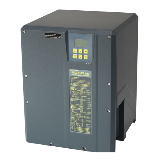
056373/D NAVIGAT 100 1.2 System Overview and Main Components Figure 1-1: NAVIGAT 100 housing Figure 1-2: Control and display unit (CDU) MENU MUTE ENTER DIM - DIM + System Overview and Main Components... -
Page 21: Door Label And Type Label
The door label at the front shows a a general Danger note, a short over- view of the power-up sequence with a belonging Warning note, the head- ing, menu and alarm displays and exemplary display and operating keys functionality for the menu and display settings of the NAVIGAT 100. Figure 1-3: NAVIGAT 100... -
Page 22: Navigat 100 Main Components
056373/D NAVIGAT 100 NAVIGAT 100 Main Components Figure 1-5: Open housing with mainboard Item Qty. NAVIGAT 100 Mainboard Bolt holes for hex head screws NAVIGAT 100 housing In figure 1-5 the front door is not shown for better understanding. System Overview and Main Components... - Page 23 NAVIGAT 100 056373/D Figure 1-6: Open housing with gyrosphere suspension Item Qty. Gyrosphere suspension Strip-wound core (for power cable insertion) Grounding strap In figure 1-6 and 1-7 the mainboard is not shown for better understand- ing. System Overview and Main Components...
- Page 24 056373/D NAVIGAT 100 Figure 1-7: Base plate and gyro- sphere suspension Item Qty. Base plate Gyrosphere suspension Strip-wound core (for power cable insertion) Grounding strap In figure 1-7 the mainboard is not shown for better understanding. System Overview and Main Components...
-
Page 25: Design And Main Features
The NAVIGAT 100 is a microprocessor controlled marine gyrocompass system with integrated automatic North speed error correction. The NAVIGAT 100, type 5026-AA, has been type approved by DNV GL SE based on the notification of the Federal Maritime and Hydrographic... - Page 26 056373/D NAVIGAT 100 Heading is measured as a 17-bit absolute value with a digital shaft encoder. The high-speed follow-up system (follow-up speed up to 100°/s) ensures that accurate heading and rate of turn data is provided under all operating conditions.
-
Page 27: Operating Principle
NAVIGAT 100 056373/D 1.4 Operating Principle The north-seeking element used in the NAVIGAT 100 system is the gyro- sphere, a hermetically sealed unit with a funnel-shaped recess, reaching from the outer skin down to its centre. Inside the gyrosphere, two mechanically linked gyroscopes are mounted with their spin axes horizontal in a carrying frame. -
Page 28: Heading Error Latitude Correlation
056373/D NAVIGAT 100 Heading Error Latitude Correlation CAUTION Risk of unstable/unreliable heading in polar waters When operating the vessel in polar waters, the heading information of the gyrocompass may become unstable/unreliable resulting in possible deviation. For safe steering in polar waters, the heading information of... - Page 29 NEVER shut down the NAVIGAT 100, while the vessel is navigating. A shut down of the NAVIGAT 100 system for good reason is only possible when the ship is NOT navigating.
-
Page 30: Example System Configurations
NAVIGAT 100 1.5 Example System Configurations Standalone Gyrocompass/TMC System As a standalone system, the NAVIGAT 100 provides North-speed error corrected true heading as well as rate of turn data. The NAVIGAT 100 receives magnetic compass heading data via NMEA input and applies magnetic variation data. -
Page 31: Dip-Switch Settings
For the usage of the respective Gyrosphere Container model (Mod. 10/3 or Mod. 10/4) with the NAVIGAT 100, it is required to appropriately set the DIP-Switch S3 directly on the NAVIGAT 100 mainboard before the installation of the respective Gyrosphere Container model. -
Page 32: Technical Data
056373/D NAVIGAT 100 1.6 Technical Data Dimensions and Weight width 404 mm height 520 mm depth 420 mm weight 19 kg incl. container Mod.10 and gyrosphere (4,5kg) Power Supply supply voltage main: 24 VDC backup: 24 VDC, including auto- matic switch over to backup sup- ply in case of main supply failure max. -
Page 33: Accuracies
NAVIGAT 100 056373/D Accuracies Heading: heading resolution 0,01° ≥ 50 Hz sampling rate accuracy according HSC mode ≤ 0.1° x secant latitude linear mean settle point error ≤ 0.1° x secant latitude static heading error ≤ 0.4° x secant latitude dynamic heading error* (range of operation within 70°... -
Page 34: Environmental Requirements
056373/D NAVIGAT 100 Environmental Requirements Temperature Conditions max. ambient temperature range, - 10 to + 55° C operation: 14 to 131° F recommended ambient opera- 20° C ± 10° C tional temperature for highest 68° F ± 14° F system longevity: ambient temperature, storage - 25 to + 70°... -
Page 35: Inputs / Outputs
NAVIGAT 100 056373/D Inputs / Outputs Data Inputs magnetic compass heading IEC 61162-1/2 position (GPS) IEC 61162-1/2 speed (Log) IEC 61162-1/2 Signal and Status Inputs steering mode status connection to P .Gnd via ext. con- (AUTO/MAN) tact, latching external heading reference selec- connection to P .Gnd via ext. -
Page 36: Third-Party Copyright
056373/D NAVIGAT 100 1.7 Third-Party Copyright Third-Party Copyright © Information: All third-party copyright content and information in relation to the docu- ment present, are and remain the intellectual property of the respective copyright owners. Any use, reproduction or distribution of third-party copyright content and information are and remain subject to the restrictions outlined in the individual documents of the respective copyright owners. -
Page 37: Declaration Of Conformity
Maritime and Hydrographic Agency of Germany. Note The current issue of the detailed Marine Equipment Directive EC Declara- tion of Conformity of Northrop Grumman Sperry Marine B.V. Hamburg is part of the client CD stock no. 56 800. For further details please contact: Northrop Grumman Sperry Marine B.V. - Page 38 056373/D NAVIGAT 100 1-20 Declaration of Conformity...
-
Page 39: Chapter 2: Operation
The supporting fluid in the gyrosphere container will start freezing at temperatures below 0° C. The NAVIGAT 100 must no longer be operated when the ambient tem- perature at the gyrocompass’ location falls below - 10° C while the com- pass is in operation or when the ambient temperature falls below 0°... - Page 40 056373/D NAVIGAT 100 CAUTION Risk of damage through unauthorized service Only authorized service personnel is allowed to remove the gyrosphere from the gyrosphere container. Always keep to the mandatory safety requirements and the correct ser- vice work procedure to remove the gyrosphere from the gyrosphere con- tainer.
-
Page 41: Display And Operating Keys
NAVIGAT 100 056373/D 2.2 Display and Operating Keys Control and Display Unit (CDU) Figure 2-1: NAVIGAT 100 control and display unit MENU MUTE ENTER DIM - DIM + Display & Operating Keys LCD Display: 6x20 character text display. • In normal operational mode: shows the heading, the heading source, and date and time. -
Page 42: Menu Timeout Function
Menu Timeout Function Note With the exception of the main heading display, any menu indication of the NAVIGAT 100 CDU temporarily and will automatically reset to the main heading display after a period of 120 seconds. TBD 2.3 External Control Devices... -
Page 43: Power-Up
Power up the system at least three hours before leaving harbour. Power down the system during long docking periods only. Make sure that the NAVIGAT 100 has settled before using its heading as the reference for heading control systems, RADAR, ECDIS, etc. - Page 44 DATE/TIME: AUTO alternating with „GYRO“ 29.JAN.2013 as long as the alignment continuous. 15:54 In case the NAVIGAT 100 is defined as a 256.4° Gyro- / Magnetic Compass system and MAGN the magnetic compass is selected as heading source, no alignment is per-...
-
Page 45: Navigat 100 Restart
Note In case of a power-off (intended or not intended) followed by a power-up within three minutes, the NAVIGAT 100 restarts in the same way, as if a restart (warm start) has been initiated. Note In case of a power-off (intended or not intended) followed by a power-up after more than three minutes, the NAVIGAT 100 executes a complete start-up routine (cold start). -
Page 46: Selecting The Active Heading Source
WARNING Limited heading data accuracy during settling time After a power-up from cold, the NAVIGAT 100 requires a settling time of three hours before reliable heading data are available. Power up the system at least three hours before leaving harbour. -
Page 47: Adjusting The Display Brightness
Left () / Right () keys are pressed. Note If the NAVIGAT 100 system is preset as gyrocompass / magnetic compass system, „GYRO/MAGN“ is displayed first on the menu display. Note If the system is configured for source selection from an external device, selection from the control and display unit is disabled. -
Page 48: Adjusting The Display Contrast
MUTE 2.8 NAVIGAT 100 CDU Initialisation If the NAVIGAT 100 CDU cable plug has been released from the NAVI- GAT 100 mainboard during service work, while the NAVIGAT 100 gyro- compass is operable, the CDU can be manually initialized to avoid a shut down of the gyrocompass. -
Page 49: Optional Functions
Note A remotely muted alarm remains in the pending (unacknowledged) state. The alarm message is shown on the display until the alarm is acknowl- edged at the NAVIGAT 100 or the cause of the alarm is eliminated. Optional Functions 2-11... -
Page 50: Operating Menu
056373/D NAVIGAT 100 2.10 Operating Menu The data display menu as well as the manual settings, user and service setup sub-menus are accessed through a multilevel operating menu. Entering and Quitting the Menu Display 256.4° 1. From the heading display, press the MENU / MUTE key. -
Page 51: Navigating The Menu
NAVIGAT 100 056373/D Navigating the Menu While the menu display is shown, the operator may navigate through the menu using the context sensitive MENU / MUTE, ENTER / ACK, Left () / Right () and DIM- /Down () | DIM+/Up () keys. -
Page 52: Choice / Selection Of Parameter Settings
056373/D NAVIGAT 100 Choice / Selection of Parameter Settings In a sub page of a sub menu, one or more parameter setting may be available. The first parameter setting is always preselected and shown in inversed lettering. A number of operational and setup parameters are set either by •... - Page 53 NAVIGAT 100 056373/D Selecting Options of Parameter Settings: Press the SELECTION 1 DIM- /Down () / DIM+/Up () keys to SELECTION 2 select the respective parameter set- SELECTION 3 ting. Press the ENTER / ACK or Right () key to check the check box of the respective parameter setting.
-
Page 54: Editing Parameter Values
056373/D NAVIGAT 100 Editing Parameter Values In a sub page of a sub menu, a number of operational and setup param- eters are set by editing a numerical or alphanumerical value. The first character of the editable parameter is always preselected and shown in inversed lettering. -
Page 55: Displaying Secondary Info
NAVIGAT 100 056373/D 2.11 Displaying Secondary Info The Secondary Info allows the operator to consecutively select Second- ary Info pages for relevant operational data, while heading and heading source remain continuously displayed. The Secondary Info is either directly available from the heading display or from the menu display. - Page 56 056373/D NAVIGAT 100 256.4° Figure 2-4: From the Heading Display, use the Left () / Right () keys to go to the Displaying GYRO secondary info desired secondary Info page. In case of pending alerts, the DATE/TIME: AUTO 29.JAN.2013...
-
Page 57: Secondary Info - North Speed Error Correction
Secondary Info - North Speed Error Correction An ongoing and accurate north speed error correction is a vital precon- dition for the heading accuracy of the NAVIGAT 100 gyrocompass. A regular status check of the north speed error correction secondary info display from time to time is advisable for the operator. -
Page 58: Manual Settings Menu
056373/D NAVIGAT 100 2.12 Manual Settings Menu The Manual Settings menu provides access to settings which the opera- tor may need to alter more or less frequently during normal operation. To access the Manual Settings: 256.4° 1. From the heading display, press the MENU / MUTE key. -
Page 59: Manual Settings - Overview
NAVIGAT 100 056373/D Manual Settings – Overview Figure 2-5: GYRO/MAGN Manual Settings SECONDARY INFO INPUT DATA input data settings MANUAL SETTINGS GPS INPUT MONITORING INFO/SERVICE MODE ENTER MANUAL LATITUDE [+/- 90°] INPUT DATA MANUAL LONGITUDE NORTH SP.ERR.CORR. [+/- 180°] MANUAL SPEED... -
Page 60: Manual Settings - Parameters
056373/D NAVIGAT 100 Manual Settings – Parameters INPUT DATA GPS INPUT Selects the GPS input mode. MODE Settings: Speed data is read automatically from the GPS. MAN (Manual) The actual speed value is entered manually. WARNING Risk of Deviation A manually entered speed value as GPS input mode may badly influence the north speed error correction functionality of the system and cause deviation. - Page 61 NAVIGAT 100 056373/D Note If MAN is selected as GPS input mode an respective warning will be raised, to highlight that automatic speed data input by GPS is the pre- ferred option. MAGN VAR (Magnetic Variation) INPUT Selects the magnetic variation input mode.
- Page 62 Risk of Deviation Loss of or invalid speed and/or position input data will flaw the north speed error correction of the NAVIGAT 100 and cause deviation. Always have in mind, that the north speed error correction needs valid speed and position input for reliable heading functionality and long time stable operation of the CompassNet system.
-
Page 63: Monitoring
NAVIGAT 100 056373/D 2.13 Monitoring The Monitoring menu provides access to settings which the operator may need to check or alter more or less frequently during normal opera- tion. To access the Monitoring menu: 256.4° 1. From the heading display, press the MENU / MUTE key. -
Page 64: Monitoring - Parameters
056373/D NAVIGAT 100 Monitoring – Parameters HDG. DIFF. (Heading Difference) MONITOR Sets the heading difference monitor parameters. USE HDG DIFF MON (Heading Difference Monitor) Activates / inactivates the heading difference monitor. none Settings: The heading difference monitor is activated / inactivated via check box. - Page 65 NAVIGAT 100 056373/D HEADING Sets the heading graph scaling of the NAVIPRINT navigation data printer. +/- 30° Settings: Scale to show 30° to the left and to the right from the graph’s centre (current print position shifts to centre when graph reaches margin) printer is activated / inactivated via check box.
-
Page 66: Info / Service
056373/D NAVIGAT 100 2.14 Info / Service The Info / Service menu provides access to settings which the operator may need to check or alter more or less frequently during normal opera- tion. To access the Info / Service menu: 256.4°... -
Page 67: Info / Service - Overview
NAVIGAT 100 056373/D Info / Service – Overview Figure 2-7: GYRO/MAGN Info / Service menu SECONDARY INFO VERSION INFO software version info MANUAL SETTINGS FIRMWARE 1.110 MONITORING INFO/SERVICE BUILD BOOTLOADER 1.050 HARDWARE INFO MORE VERSIONS CCU FIRMWARE 1.110 VERSION INFO... -
Page 68: Info / Service - Parameters
The version info of the CCU controller is listed under INFO/SERVICE VERSION INFO / MORE VERSIONS SYSTEM STATUS Displays various system status information. The System Status sub menu is not functional for the NAVIGAT 100 SOUND KEY CLICKS Activates / inactivates the sound key clicks functionality. none... -
Page 69: Chapter 3: Alerts And Errors
(CAM) according to specified standards ISO 16328 and IEC 61924-2. Note All alerts of the NAVIGAT 100 gyrocompass system are category B alerts according to IEC 61924-2. Note From software version 1.110 on, the NAVIGAT 100 supports the respon- sibility transfer of alerts according IEC 61924-2. -
Page 70: Alert Indication
056373/D NAVIGAT 100 3.1 Alert Indication Audible Alert Indication Single Beep: Invalid Action A single short beep indicates that the operator attempted to carry out an invalid action. This is the case, e.g. if the operator tries to change the head- ing reference in an automatic steering mode or to activate a heading source from which no valid data is received. -
Page 71: Visual Alert Indication
056373/D Visual Alert Indication Note The alert handling of the NAVIGAT 100 gyrocompass system differenti- ates between alarm and warning conditions. Throughout the alert handling, several sequential alarm and warning dis- plays describe the different status of alarms and warnings. -
Page 72: Alert Handling
In case of pending alarm and warning conditions at the same time, the alert conditions will be listed before the warning conditions. Note All alerts of the NAVIGAT 100 gyrocompass system are category B alerts according to IEC 61924-2. Alarm Displays Active Unacknowledged Alarm 356.4°... - Page 73 Transferred Alarm (Responsibility transferred by CAM) 356.4° If the responsibility of a pending active alarm is transferred by the CAM, the GYRO1 NAVIGAT 100 display continuous to ALARM 1/2 show the heading data from the selected ID:511 compass (GYRO respectively MAGN).
- Page 74 056373/D NAVIGAT 100 Active Acknowledged Alarm Press ENTER / ACK to acknowledge a 356.4° pending (active) alarm. GYRO1 ALARM 1/2 The audible alarm is permanently ID:511 muted. TIMEOUT GPS1 The display continuous to show the heading data from the selected compass...
- Page 75 When a cause of a pending unacknowledged alarm is eliminated, the alarm stays in the alert list for fault diagnostics. The NAVIGAT 100 does not keep a history of acknowledged inactive alarms. Alert Handling...
-
Page 76: Warning Displays
056373/D NAVIGAT 100 Warning Displays Active Unacknowledged Warning 356.4° In case of pending active warnings, the NAVIGAT 100 display continuous to GYRO1 show the heading data from the selected WARNING 2/2 compass (GYRO respectively MAGN). ID:694 An audible alarm tone is raised. - Page 77 NAVIGAT 100 056373/D Active Muted Warning Press MENU / MUTE to mute a pending 356.4° (active) unacknowledged warning. GYRO1 WARNING 2/2 The audible alarm is muted for a lim- ID:694 ited period of time (default = 30 Sec). GYRO SIM. ACTIVE...
- Page 78 When a cause of a pending unacknowledged warning is eliminated, the warning stays in the alert list for fault diagnostics. The NAVIGAT 100 does not keep a history of acknowledged inactive warnings. 3-10...
-
Page 79: Alerts / Check
056373/D 3.3 Alerts / check The following table lists a complete list of all NAVIGAT 100 alerts (A = alarm, W = warning) which become indicated on the display and in the alert list when an alert is active. All alerts are indicated with a unique alert ID and a double spaced alert text. - Page 80 056373/D NAVIGAT 100 Alert Alert Alert Text Cause Corrective Type Action ILLEGAL CONF Invalid setup Restart system SETUP CONFIG FAILURE Invalid setup / Apply correct SETUP double GPS/ GPS/LOG alloca- LOG allocation tion HEADING DIFF False setting or • Adjust sys- HDG DIFF .
- Page 81 NAVIGAT 100 056373/D Alert Alert Alert Text Cause Corrective Type Action NO VALID HEADING No valid head- • Select active HDG MANAGER ing source heading source • Exchange defective heading sen- 180° WHILE AUTO 180° switch Change to man- HDG MANAGER...
- Page 82 056373/D NAVIGAT 100 Alert Alert Alert Text Cause Corrective Type Action CRITICAL TEMP . NG 100 opera- Check cooling GYRO tional tempera- fan function ture in alarm range HEAT - POWER OFF NG 100 opera- • Check cool- GYRO tional tempera-...
- Page 83 NAVIGAT 100 056373/D Alert Alert Alert Text Cause Corrective Type Action CRIT. ENC. STATE Encoder func- • Restart sys- GYRO tion status in alarm range • Check encoder con- nection / per- form baseplate test ENC. STATE FAIL Encoder func-...
- Page 84 056373/D NAVIGAT 100 Alert Alert Alert Text Cause Corrective Type Action FAN 2 FAIL Fan function • Check cool- GYRO failed, in alarm ing fan func- range tion • Replace cool- ing fan in case error persists GYRO FREQ Gyrosphere...
- Page 85 NAVIGAT 100 056373/D Alert Alert Alert Text Cause Corrective Type Action HIGH ROT ERROR ROT deviation • Restart sys- GYRO in warning range • Perform baseplate test CRIT. ROT ERROR ROT deviation • Restart sys- GYRO in alarm range •...
- Page 86 056373/D NAVIGAT 100 Alert Alert Alert Text Cause Corrective Type Action ENC. COMM FAIL Encoder com- • Restart sys- GYRO munication failed • Perform baseplate test • Call Sperry Marine ser- vice to exchange baseplate if error persists BASEPLATE Baseplate test •...
-
Page 87: Chapter 4: Scheduled Maintenance
Make sure to regularly clean the air inlet grill from dust and dirt and check the fan functionality to avoid overheating. Sperry Marine recommends to regularly clean the air inlet grill of the fan and to check the functionality of the fan with every gyrosphere mainte- nance interval latest, as this is mandatory to avoid overheating of the gyrocompass. -
Page 88: Gyrosphere Maintenance
If necessary, the centering pin is exchanged. The NAVIGAT 100 is counting the system operating hours automatically until a maximum level (18 months) is reached. When the maximum level of operating hours is reached, the following message is displayed auto-... -
Page 89: Five-Year Maintenance
Five-Year Maintenance To ensure continued trouble-free operation and to minimize the risk of failure, Sperry Marine recommends that every five years, the gyro- sphere and the centering pin are exchanged by authorized service per- sonnel. - Page 90 056373/D NAVIGAT 100 Gyrosphere Maintenance...
-
Page 91: Chapter 5: Preventive Maintenance
The supporting fluid in the gyrosphere container will start freezing at temperatures below 0° C. The NAVIGAT 100 must no longer be operated when the ambient tem- perature at the gyrocompass’ location falls below -10° C while the com- pass is in operation or when the ambient temperature falls below 0° C while the gyrocompass is not in operation. -
Page 92: Gyrosphere Damage Through Shut Down
NEVER shut down the NAVIGAT 100, while the vessel is navigating. A shut down of the NAVIGAT 100 system for good reason is only possible when the ship is NOT navigating. -
Page 93: Removing The Gyrosphere Container From The Compass Housing
Life danger through electrical shock When the NAVIGAT 100 compass is energized, the gyrosphere operating voltage of 100 VAC @ 333 Hz is present on the NAVIGAT 100 mainboard, the gyrosphere supply lines, and across the gyrosphere contacts. Make sure that the main and backup power supplies of the compass are... - Page 94 Note The NAVIGAT 100 CDU cable is still plugged to socket J 14 of the NAVI- GAT 100 mainboard and must be released before the door can be placed aside.
- Page 95 NAVIGAT 100 056373/D 8. Unplug the gyrosphere supply and pick off connector from its socket on the pick off PCB. 9. Turn the bellows, until the largest of the three coupling seats in the bayonet collar points towards the front of the housing.
- Page 96 056373/D NAVIGAT 100 16. Put the door in front of the housing and reconnect the grounding strap. 17. Fit the door back on the housing and tighten the hex head screws. Note Take the necessary precautions to make sure that the compasses main and backup power supplies remain switched off while the container is not installed.
-
Page 97: Installing The Gyrosphere Container In The Compass Housing
Life danger through electrical shock When the compass is energized, the gyrosphere operating voltage of 100 VAC @ 333 Hz is present on the NAVIGAT 100 mainboard, the gyro- sphere supply lines, and across the gyrosphere contacts. When the AC main supply is switched on, hazardous life voltages are present at the line filter and the power transformer’s terminals. - Page 98 Note The NAVIGAT 100 CDU cable is connected to the NAVIGAT 100 main- board and must be released before the door can be placed aside. 5. To disconnect the jack of the...
- Page 99 NAVIGAT 100 056373/D 9. Place the gyrosphere container into the compass housing with the largest of the three coupling seats located directly below the groove in the collar. Note The largest of the three coupling seats is marked by a green dot on the collar.
- Page 100 The gyrocompass is now ready to be put into operation. In case the NAVIGAT 100 is put into operation and the CDU stays blank, the CDU must be manually initialized by pressing the DIM- / Down () + DIM+ / Up () keys simultaneously to enter operable mode, see “NAVIGAT 100 CDU Initialisation”...
-
Page 101: Chapter 6: System Installation
Chapter 6: System Installation 6.1 Installation Recommendations The compact, space saving and low weight single unit design of the NAVIGAT 100 gyrocompass allows it to become installed at virtually any location on board and on any bridge. However, certain recommendations regarding environmental and installing conditions exist, to enable best performance of the NAVIGAT 100 system For the required environmental conditions, see ”General... -
Page 102: Vibration
056373/D NAVIGAT 100 Vibration The gyrocompass is designed to work trouble free in Area A classified locations according to Germanischer Lloyd vibration level classification, see also ”Vibration” on page 1-16 for details. The gyrocompass will show best operational performance if minimal vibration levels are kept at place of installation. -
Page 103: Mechanical Installation
Gyrosphere Container Mod. 10/4 = „Navigat“: (jumpers set to the RIGHT) See also the separate Service Procedures 05000-0125-03 for details. Note The procedures for operation of the NAVIGAT 100 Gyrocompass System with the Gyrosphere Container Mod 10/4 are described in the separate Service Procedures 05000-0125-03. -
Page 104: Gyrosphere Container Mod 10/4 Preliminaries
See ”DIP-Switch Settings” on page 6-8 for details. • The baseplate cable must be removed from connector J3 Gyro ana- logue and connected to J4 Gyro digital on the NAVIGAT 100 main- board. See ”Connectors” in ”Location of Parts on the NAVIGAT 100 Main- board”... -
Page 105: Electrical Installation
Never install the power supplies of the NAVIGAT 100 without using the strip-wound core. Note The NAVIGAT 100 is designed to operate with 24 VDC main power and a 24 VDC backup power supply. Therefore no specific safety instructions are mandatory during electrical... -
Page 106: Wiring Up The System
Risk of malfunction through wrong wiring Wrong wiring, especially as running wires from one side of the compass housing to the other or across the NAVIGAT 100 mainboard will cause malfunction. Always use the cable inlets on both sides of the compass housing for accurate wiring and keep all wires running inside the housing as short as possible. -
Page 107: Gyrosphere Installation
- 05000-0125-003, or gyrosphere type 3, gyrosphere container mod. 10/4. Note Correct jumper settings, to be set at the gyrosphere container mod. 10/4, are mandatory for trouble-free operation with the NAVIGAT 100 gyro- compass system. See the separate Service Procedures 05000-0125-03 for details. -
Page 108: Dip-Switch Settings
For the usage of the respective Gyrosphere Container model (Mod. 10/3 or Mod. 10/4) with the NAVIGAT 100, it is required to appropriately set the DIP-Switch S3 directly on the NAVIGAT 100 mainboard before the installation of the respective Gyrosphere Container model. -
Page 109: Initial System Configuration
Life danger through electrical shock When the compass is energized, the gyrosphere operating voltage of 100 VAC @ 333 Hz is present on the NAVIGAT 100 mainboard, the gyro- sphere supply lines and across the gyrosphere contacts. Be extremely careful when operating the compass while the housing is open. - Page 110 If the system is energized without installed gyrosphere, the system will raise a „GYROPOWER FAIL“ alarm. Power down the system and install the gyrosphere before the configuration of the NAVIGAT 100. Go to the ”Service Setup 600” ”SYSTEM SETTINGS” on page 7-7. 8. Edit the required ship information settings.
-
Page 111: Finalizing The Installation
NAVIGAT 100 056373/D Finalizing the Installation 1. Go to the”Manual Settings Menu” on page 2-20. 2. Set the input data parameters in the Manual Settings menu to suita- ble values. Wherever possible, automatic data input should be selected in preference of manual input. -
Page 112: Alignment Error Correction
056373/D NAVIGAT 100 6.7 Alignment Error Correction CAUTION Risk of inaccurate alignment error correction The compass must have been in continuous operation for at least 4 hours before the alignment error can be determined accurately. If bearing repeaters are used to determine the true heading, these must be properly aligned to the vessel's fore-and-aft axis. -
Page 113: Performing Alignment Error Correction
NAVIGAT 100 056373/D Performing Alignment Error Correction 1. Determine the existing alignment error by comparing the compass heading with the vessel's true heading. The true heading must be known to an accuracy of at least 0.5°. 2. Go to the ”Service Setup 600”... -
Page 114: Magnetic Compass Calibration
The magnetic compass heading calibration corrects deviations due to the combined effects of the magnetic environment, the particular sensor being used and the receiving circuitry on the NAVIGAT 100 mainboard. Therefore, a new calibration must always be carried out when:... - Page 115 DATE/TIME: AUTO 29.JAN.2013 magnetic compass heading val- 15:54 ues shown on the NAVIGAT 100 display. At every full 10° of steering magnetic compass heading (0°, 10°, …, 350°), note all the dis- Mag. HDG Mag.
- Page 116 056373/D NAVIGAT 100 Storing the magnetic compass heading calibration table 1. Go to the ”Service Setup 600” ”MAGN (Magnetic Compass) SEN- SOR SETUP” sub menu on 7-24. 2. Call up the „Magn Cal Tab“ sub-menu. The calibration table entry sub-menu is shown.
-
Page 117: Installation Check Procedures
NAVIGAT 100 056373/D 6.9 Installation Check Procedures To finish the installation of the NAVIGAT 100 gyrocompass system, it is mandatory to check all installation and system configuration conditions with the following installation check procedures. Note Use also the NAVIGAT 100 Installation Checklist Record Sheet 04914-0125-10 in the appendix of this manual. -
Page 118: Electrical Installation Check Procedure
NAVIGAT 100 Electrical Installation Check Procedure 1. Check if the NAVIGAT 100 main power and back up power supply (floating relative to ships ground) present is 24 VDC. 2. Check if all wiring of the NAVIGAT 100 gyrocompass is performed according to the applicable standard or project specific connection drawings. - Page 119 056373/D 3. Check that the DIP-Switch S3 is set appropriately directly on the NAVIGAT 100 mainboard for the usage of the respective Gyrosphere Container model (mod. 10/3 or mod. 10/4). 4. Power-up the system and wait until the complete start-up routine is successfully executed, see “Power-up”...
- Page 120 056373/D NAVIGAT 100 6-20 Installation Check Procedures...
-
Page 121: Chapter 7: System Configuration
Chapter 7: System Configuration The different Service Setup menus provide access to the system param- eters which configure the NAVIGAT 100 system according to the require- ments of the installation at hand. The Service Setup menus also provide test modes to check the proper function of the system hardware installed. -
Page 122: Service-Setup 600 - Overview
056373/D NAVIGAT 100 Service-Setup 600 – Overview Figure 7-1: HEADING CORR. VALUE editing of heading Service Setup 600 correction value [+/- 180 °] ship, type, speedfilter, SYSTEM SETTINGS sound settings SHIP INFORMATION IMO REGISTRATION NO 0000000 HEADING CORR. VALUE SYSTEM SETTINGS... - Page 123 NAVIGAT 100 056373/D Figure 7-2: contd. from previous page OUTPUT MANAGER output interface settings Service Setup 600 SENSOR DATA OUT (contd.) SENSOR DATA OUT 1-3, 5, 6 PROTOCOL TYPE NMEA COURSE BUS HEADING CORR. VALUE SYSTEM SETTINGS NMEA TX PATTERN...
- Page 124 056373/D NAVIGAT 100 Figure 7-3: contd. from previous page OUTPUT MANAGER output interface settings Service Setup 600 REPEATER OUT (contd.) TB4 TOP 1-2, BOTTOM 1-2 PROTOCOL TYPE NMEA COURSE BUS HEADING CORR. VALUE SYSTEM SETTINGS NMEA TX PATTERN INTERFACE SETUP...
- Page 125 NAVIGAT 100 056373/D Figure 7-4: contd. from previous page INPUT MANAGER output interface settings Service Setup 600 GPS INPUT (contd.) NMEA MESSAGE MODE AUTO MANUAL MESSAGE HEADING CORR. VALUE SYSTEM SETTINGS NMEA BAUDRATE INTERFACE SETUP MAGN SENSOR SETUP 4800 INTERNALS...
- Page 126 056373/D NAVIGAT 100 Figure 7-5: contd. from previous page input interface settings Service Setup 600 NMEA BAUDRATE (contd.) 4800 9600 38400 NMEA MESSAGE SELECT HEADING CORR. VALUE SYSTEM SETTINGS INTERFACE SETUP MAGN SENSOR SETUP ALR/ACK INTERNALS ACN/ALF/ALC RESTART TESTALARM ACTIVE...
-
Page 127: Service Setup 600 - Parameters
NAVIGAT 100 056373/D Service Setup 600 – Parameters HEADING CORR. (Correction) VALUE Editing of the heading correction value. Value: [+/- 180°] Default value: „000.0“ SYSTEM SETTINGS SHIP INFORMATION Editing of ship information entries. IMO REGISTRATION NO Entry: 1234567 (numerical, 7 digits) - Page 128 056373/D NAVIGAT 100 SPEED FILTER Sets the filter parameters used for the North speed error correction.The pre set factory defaults should not normally be altered. In high speed craft, however, it will be necessary to increase the maximum speed value to prevent rejection of valid high speed values.
- Page 129 Default setting: „active“ ALERT PRESENT. (Presentation) DELAY The alert presentation delay setting is used to enable alert responsibility transfer by the CAM, before the alert is indicated at the NAVIGAT 100 CDU. Value: [0 – 5 s] Default value: „3“...
- Page 130 * The NMEA baudrate (4800, 9600 and 38400) is selectable for all NMEA TX patterns; NMEA baudrate 4800 is default setting. ** NMEA Message Select is always possible for each NMEA TX pattern. *** The NAVIGAT 100 does not transmit rates, angles. Data Message...
- Page 131 NAVIGAT 100 056373/D SENSOR DATA OUT SENSOR DATA OUT 1-3, 5, 6 The SENSOR DATA OUT 1-3, 5 and 6 output settings are identical. PROTOCOL TYPE Settings: NMEA The sensor data out output setting is defined for transfer of NMEA message type.
- Page 132 056373/D NAVIGAT 100 NMEA MESSAGE SELECT GYRO HEADING Settings: No gyrocompass heading messages are transferred by the gyrocompass. --HDT The NMEA --HDT message is selected as gyrocompass heading = default setting. --THS The NMEA --THS message is selected as gyrocompass heading.
- Page 133 NAVIGAT 100 056373/D HDG REF. STATUS The heading reference status output is inactivated. PPLAN The proprietary PPLAN message is selected for the heading reference status output. PPNSD The proprietary PPNSD message is selected for the heading reference status output. --STN The NMEA --STN message is selected for the heading refer- ence status output.
- Page 134 056373/D NAVIGAT 100 SENSOR DATA OUT SENSOR DATA OUT 4 The SENSOR DATA OUT 4 output setting provides additionally a proto- col type selection for NMEA or PRINTER output. PROTOCOL TYPE Settings: NMEA The sensor data out 4 output setting is defined for transfer of NMEA message type.
- Page 135 NAVIGAT 100 056373/D NMEA MESSAGE SELECT GYRO HEADING Settings: No gyrocompass heading messages are transferred by the gyrocompass. --HDT The NMEA --HDT message is selected as gyrocompass heading = default setting. --THS The NMEA --THS message is selected as gyrocompass heading.
- Page 136 056373/D NAVIGAT 100 HDG REF. STATUS The heading reference status output is inactivated. PPLAN The proprietary PPLAN message is selected for the heading reference status output. PPNSD The proprietary PPNSD message is selected for the heading reference status output. --STN The NMEA --STN message is selected for the heading refer- ence status output.
- Page 137 NAVIGAT 100 056373/D REPEATER OUT TB4 TOP1-2, BOTTOM 1-2 The REPEATER OUT TB4 TOP 1-2 and BOTTOM 1-2 output settings are identical. PROTOCOL TYPE Settings: NMEA The sensor data out output setting is defined for transfer of NMEA message type.
- Page 138 056373/D NAVIGAT 100 NMEA MESSAGE SELECT GYRO HEADING Settings: No gyrocompass heading messages are transferred by the gyrocompass. --HDT The NMEA --HDT message is selected as gyrocompass heading = default setting. --THS The NMEA --THS message is selected as gyrocompass heading.
- Page 139 NAVIGAT 100 056373/D HDG REF. STATUS The heading reference status output is inactivated. PPLAN The proprietary PPLAN message is selected for the heading reference status output. PPNSD The proprietary PPNSD message is selected for the heading reference status output. --STN The NMEA --STN message is selected for the heading refer- ence status output.
- Page 140 056373/D NAVIGAT 100 INPUT MANAGER The input manager defines the GPS, the LOG (speed log) and magnetic compass heading input settings regarding NMEA message mode, NMEA baudrate and NMEA message selection. GPS INPUT NMEA MESSAGE MODE Defines the interface protocol for the external GPS input.
- Page 141 NAVIGAT 100 056373/D LOG INPUT NMEA MESSAGE MODE Defines the interface protocol for the external LOG input. Settings: The NMEA message mode is defined that no LOG input is received. AUTO The NMEA message mode is defined that the LOG input is received automatically = default setting.
- Page 142 056373/D NAVIGAT 100 MAGN HDG (Magnetic Compass Heading) INPUT NMEA MESSAGE MODE Defines the interface protocol for the external magnetic compass heading input. Settings: The NMEA message mode is defined that no magnetic com- pass heading input is received. AUTO...
- Page 143 NAVIGAT 100 056373/D NMEA MESSAGE SELECT Settings: The HDM message is selected as magnetic compass head- ing input = default setting. The HDG message is selected as magnetic compass head- ing input. WARNING Risk of deviation In case the magnetic compass is selected as active heading source and...
- Page 144 056373/D NAVIGAT 100 MAGN (Magnetic Compass) SENSOR SETUP Configures the setup of the magnetic compass sensor. TIME CONST. MAGN HDG (Constant Magnetic Compass Head- ing) Defines the time constant for the external magnetic compass heading input. Value: [0 - 99 s] Default value: „00.0“...
-
Page 145: Service Setup 610
NAVIGAT 100 056373/D 7.2 Service Setup 610 The Service Setup 610 menu provides access to the gyrosphere system status and operational data. Furthermore, an option is provided to initiate a warm start of the gyro- sphere container software without interruption of the power supply. For details see “WARMSTART CONTAINER”... -
Page 146: Service-Setup 610 - Overview
056373/D NAVIGAT 100 Service-Setup 610 – Overview Figure 7-6: GYROSPHERE DATA gyrosphere current / Service Setup 610 voltage values GYRO CURRENT 0.225 A GYRO VOLTAGE 100.90 V gyrocompass TEMPERATURE temperature TEMP 1 44° C values TEMP 2 38° C GYROSPHERE DATA TEMP 3 50°... -
Page 147: Service Setup 610 - Parameters
NAVIGAT 100 056373/D Service Setup 610 – Parameters GYROSPHERE DATA Note The gyrosphere current and temperature values are constantly moni- tored by the system. In case the gyrosphere current and/or temperature values get out of a reasonable operating range corresponding alert messages will be issued to indicate alert level and error type. - Page 148 NAVIGAT 100 TEMPERATURE Displays different checkpoint temperature values according to NAVIGAT 100 checkpoints. Checkpoints 1 and 2 are located on the NAVIGAT 100 mainboard. Check- point 3 is located within the NAVIGAT 100 power module. TEMP 1 (Temperature) Value: 44° C The temperature 1 value given is an example.
- Page 149 NAVIGAT 100 056373/D INPUT STATUS Displays system input details and error information for control and trou- bleshooting. GPS INPUT Input MESSAGES RECEIVED details: MESSAGES OVERRUN CHECKSUM ERRORS DATA ERRORS BYTE ERRORS LOG INPUT Input MESSAGES RECEIVED details: MESSAGES OVERRUN CHECKSUM ERRORS...
- Page 150 056373/D NAVIGAT 100 WARMSTART CONTAINER Initiates a reset (warm start) of the NAVIGAT 100 gyrosphere container software. All volatile values stored in the container, including the current heading are reset and initial self checks are performed. If the compass has been already aligned before, the heading becomes immediately valid after these tests without starting a new alignment.
-
Page 151: Service Setup 106
NAVIGAT 100 056373/D 7.3 Service Setup 106 The Service Setup 106 menu provides sensor simulation and relay simu- lation information. Note During sensor simulation, the system remains operable. Any changes of the system functionality are kept, when the sensor simu- lation menu is left. -
Page 152: Service-Setup 106 - Overview
056373/D NAVIGAT 100 Service-Setup 106 – Overview Figure 7-7: SENSOR SIMULATOR sensor simulation Service Setup 106 SIMULATOR VALUES HEADING VALUE [0 - 360 °] ROT VALUE [+/- 9999 °/min] SENSOR SIMULATOR RELAIS SIMULATOR SIMULATOR MODES SIMULATOR OFF CONSTANT ROT CONSTANT HEADING SEQUENCE SIM. -
Page 153: Service Setup 106 - Parameters
NAVIGAT 100 056373/D Service Setup 106 – Parameters SENSOR SIMULATOR Note A restart is always automatically executed when the SENSOR SIMULA- TOR menu is quit in case at least one setting was altered. SIMULATOR VALUES Editing masks for simulation of heading and ROT values of the sensor are provided. - Page 154 056373/D NAVIGAT 100 SEQUENCE SIM. (Simulator) none Settings: The sequence simulator function is activated / inactivated via check box. Default setting: „inactive“ A predefined heading / ROT sequence simulation is started. 7-34 Service Setup 106...
- Page 155 NAVIGAT 100 056373/D RELAY SIMULATOR Note A restart of the CSU controller is always executed when quitting the RELAY SIMULAOR, no matter if relay settings have been activated or not. Note A restart of the CSU controller is always executed when quitting the RELAY SIMULAOR, no matter if relay settings have been activated or not.
-
Page 156: Service Setup 998
056373/D NAVIGAT 100 7.4 Service Setup 998 The Service Setup 998 menu provides several system hardware tests. Setup Access Code To access the Service Setup 998 menu: 1. From the heading display, press the MENU / GYRO/MAGN MUTE key. SECONDARY INFO MANUAL SETTINGS ... -
Page 157: Service-Setup 998 - Overview
NAVIGAT 100 056373/D Service-Setup 998 – Overview Figure 7-8: BASEPLATE TEST system hardware tests Service Setup 998 the test is immediately executed, when entered BACKLIGHT TEST the test is immediately executed, when entered BASEPLATE TEST BACKLIGHT TEST ERROR LED TEST... - Page 158 056373/D NAVIGAT 100 HORN TEST Initiates test of the system horn (alarm sound). none Settings: The horn is one time executed when entered. 7-38 Service Setup 998...
-
Page 159: Chapter 8: Troubleshooting
Life danger through electrical shock When the compass is energized, the gyrosphere operating voltage of 100 VAC @ 333 Hz is present on the NAVIGAT 100 mainboard, the gyro- sphere supply lines and across the gyrosphere contacts. Be extremely careful when operating the compass while the housing is open. -
Page 160: Location Of Parts On The Navigat 100 Mainboard
056373/D NAVIGAT 100 8.2 Location of Parts on the NAVIGAT 100 Mainboard Figure 8-1 below shows the locations of parts and connectors on the NAVIGAT 100 mainboard. Figure 8-1: Location of parts on the NAVIGAT 100 mainboard Location of Parts on the NAVIGAT 100 Mainboard... -
Page 161: Terminal Boards
24 VDC main supply power in NAVIGAT 100 mainboard TB 2 24 VDC backup supply power in TB 3 Sensor Data Out TB 4 Sensor Data Out TB 5 (divers functionalities) TB 6 (SIN/COS, not functional) Location of Parts on the NAVIGAT 100 Mainboard... -
Page 162: Connectors
Diagnostic LEDs As an aid in troubleshooting, a number of diagnostic LED indicators are provided on the NAVIGAT 100 Mainboard. These indicate the presence of supply voltages, activities on the serial data I/O lines and the current states of the status I/O ports. -
Page 163: Chapter 9: Corrective Maintenance
NAVIGAT 100 056373/D Chapter 9: Corrective Maintenance The NAVIGAT 100 is generally not field-serviceable on the component level. In case of malfunction, complete sub-assemblies must be exchanged and the defective sub-assemblies returned to Sperry Marine. Unless instructed otherwise by Sperry Marine engineering, field service personnel should limit troubleshooting to exchanging (generally updat- ing) the system software. -
Page 164: Navigat 100 Software Update
Life danger through electrical shock When the compass is energized, the gyrosphere operating voltage of 100 VAC @ 333 Hz is present on the NAVIGAT 100 mainboard, the gyro- sphere supply lines and across the gyrosphere contacts. Be extremely careful when operating the compass while the housing is open. - Page 165 Unless instructed otherwise by Sperry Marine engineering, field service personnel should limit troubleshooting to exchanging (generally updat- ing) the system software. Updating the system software of the NAVIGAT 100 is by means of two separate USB service interfaces on the NAVIGAT 100 mainboard: •...
-
Page 166: Software Update Procedure
Note The NAVIGAT 100 CDU cable is still plugged to socket J 14 of the NAVIGAT 100 mainboard and must be released before the door can be placed aside. - Page 167 PIN empty. 11. Plug in the type B connector of the USB cable at the J31 USB service port on the NAVIGAT 100 main- board. Note The sequence of usage of the USB service ports (J31/J32) for software update is free.
- Page 168 15. The following blank SUSI screen indicates at the status line, that SUSI is connected with CSU. The LED symbol at the top of the screen should have changed its col- our to green: NAVIGAT 100 Software Update...
- Page 169 16. Click the „Update“ tab on the left, to indicate the following screen: 17. Click the button to call up the file open dialogue. Then, navigate to the folder with the GUD update file, open the folder, select the GUD update file and click NAVIGAT 100 Software Update...
- Page 170 The bargraph at the bottom of the screen indicates the progress of the update: Instead of flashing constantly, the green LED „Work“ (CR 13) on the NAVIGAT 100 mainboard is repeatedly illuminated during the update process. NAVIGAT 100 Software Update...
- Page 171 As soon as one plug of the USB cable is unplugged the CCU control- ler automatically reboots with the new firmware. During the reboot, the red LED CR 14 on the NAVIGAT 100 main- board is several times illuminated.
- Page 172 096 (for CSU controller update via J32 service port) and plug in the type B connector of the USB cable at the J32 USB service port on the NAVIGAT 100 main- board. 22. The “Online” button at the top of SUSI’s main screen should now become clickable (not greyed-out): 23.
- Page 173 25. Click the „Update“ tab on the left, to indicate the following screen: 26. Click the button to call up the file open dialogue. Then, navigate to the folder with the GUD update file, open the folder, select the GUD update file and click NAVIGAT 100 Software Update 9-11...
- Page 174 The bargraph at the bottom of the screen indicates the progress of the update: Instead of flashing constantly, the green LED „Work“ (CR 17) on the NAVIGAT 100 mainboard is repeatedly illuminated during the update process. 9-12 NAVIGAT 100 Software Update...
- Page 175 As soon as one plug of the USB cable is unplugged the CSU control- ler automatically reboots with the new firmware. During the reboot, the red LED CR 16 „Error“ on the NAVIGAT 100 mainboard is several times illuminated.
- Page 176 056373/D NAVIGAT 100 9-14 NAVIGAT 100 Software Update...
-
Page 177: Chapter 10: Navigat 100 Spare Parts
NAVIGAT 100 056373/D Chapter 10: NAVIGAT 100 Spare Parts 10.1 Illustrated Parts List (IPL) Overview Table 10-1: Spare Part Name Stock No. IPL of system NAVIGAT 100 Housing 025931-0000-000 component spare parts NAVIGAT 100 Door 025932-0000-000 incl. NAVIGAT 100 CDU, Display PCB,... - Page 178 Note For the exchange of the cooling fan, stock no. 025925-0000-000, only the original Sperry Marine spare part is allowed. Never use standard PC components as spare part for the cooling fan. Note * The parts lists of the gyrosphere installation kits 005026-0126-001 (mod.
-
Page 179: Abbreviations
NAVIGAT 100 056373/D Abbreviations Note The following list contains abbreviations and shortcuts used in this man- ual and in displayed text of CDU menus. 1x1 frame Standard frame 96x96 mm 6 step/° scale measure setting of servomotor A/DO-160 Section A, DO-160E, Environmental Conditions and... - Page 180 056373/D NAVIGAT 100 CAL. Calibration Central Alert Management cal. no. s. Calibration numbers CCFL Cold Cathode Fluorescent Lamp Control and Display Unit CompassNet CN Bus CompassNet Bus (Ethernet) Course over ground COMP Compass Comp. Mon. Compass monitor CONST. Constant contd.
- Page 181 NAVIGAT 100 056373/D Dynamic positioning dwg. drawing East European Union Council ECCN Export Control Classification Number ECDIS Electronic Chart Display and Information System Environmental conditions EM-Log Electromagnetic (speed) log European Norm ERR.STAT.BITS Validity check of fiber-optic sensor data status electrostatic discharge ext.
- Page 182 056373/D NAVIGAT 100 Grounding avoidance system Gen. General NMEA sentence which provides the GPS current fix data. Germanischer Lloyd Geographic position - latitude/longitude GMDSS Global Maritime Distress and Safety System Ground GNSS Global Navigation Satellite System Global Positioning System Global Positioning System...
- Page 183 NAVIGAT 100 056373/D Input/Output Integrated circuit Interface Control Document Identifier International Electro Technical Commission International hydrographic office. International Maritime Organization Inertial Measurement Unit Integrated navigation system INT HDG ONLY Internal heading only INT/EXT HDG Internal or external heading International Protection...
- Page 184 056373/D NAVIGAT 100 LEHMK Lehmkuhl (transmission standard company Lehm- kuhl) Line feed Litef Faser Kreisel (Litef fiber optic gyroscope) lon. Longitude Lon. Longitude LORAN Long Range Navigation LORAN-C Long Range Navigation C Least significant Bit Magnetic Mag Hdg. Inp. Magnetic heading input MAGN.
- Page 185 NAVIGAT 100 056373/D Maritime Safety Committee MTBF Mean time between failure North NAUT-AW Class notation with augments requirements for bridge congfiguration for ships largely operating largely in coastal and narrow waters NAUT-HSC Class notation for high speed craft NAUT-OC Class notation with fundamental requirements for...
- Page 186 056373/D NAVIGAT 100 NMEA-RMC NMEA-RMC sentence n.o. Normally open Normally open Number None Volatile RAM Off Hdg Off heading alarm OUTP Output Pulse P .Gnd Power ground Part number Pre-programmed IC Printed circuit board PLATH Binary protocol of company C. Plath...
- Page 187 NAVIGAT 100 056373/D Ref. Voltage Reference voltage Recommended minimum navigation information Recommended minimum navigation information NMEA sentence A Recommended minimum navigation information NMEA sentence B Recommended minimum navigation information NMEA sentence C Root mean square Read Only Memory Rudder order status...
- Page 188 056373/D NAVIGAT 100 Switch-over unit SPEED N No speed SRAM Static RAM Abbreviation for speed log Stat. Status stb. Starboard Speed through water (ship's speed, as measured rela- tive to the water). SUSI Sperry universal service instrument SVDR Simplified voyage data recorder TB 3.11 (external input port)
- Page 189 NAVIGAT 100 056373/D Water speed and heading Voyage management system VMS/ECDIS Voyage management system / electronic chart display and information system VOSS Vessel optimization & safety system Vpp. Voltage peak to peak Velocity through ground Vessel traffic service Watt West...
- Page 190 056373/D NAVIGAT 100...
-
Page 191: Appendix
Magnetic Compass Calibration table are left intact when the software is exchanged. After installation of the NAVIGAT 100 and before any exchanging the sys- tem software IC, record all parameter settings in the setup and configu- ration tables to be able to re-enter them manually, if required. - Page 192 All appended drawings are revision-controlled separately at Sperry Marine. In case of doubt, verify the current revision status of the draw- ings with Sperry Marine. This manual’s revision status does not automat- ically change in time in case the revision of an appended drawing changes.
- Page 193 USE PRINTER PAPER SPEED HEADING 60 mm/h ± 30° 150 mm/h ± 180° 600 mm/h MAX ROT ALARM ______ °/min. Northrop Grumman Sperry Marine B.V. (Representative Office) Woltmanstr. 19, D-20097 Hamburg, Germany Tel.: +49-40-299 00-0, Fax: +49-40-299 00-298, E-mail: service.de@sperry.ngc.com...
- Page 194 REVISION ______ ______ HOURS ______ ______ SYSTEM INFO CPU TICKS SYSTEM DATE SYSTEM TIME ______ ______ ______ SOUND KEY CLICKS Northrop Grumman Sperry Marine B.V. (Representative Office) Woltmanstr. 19, D-20097 Hamburg, Germany Tel.: +49-40-299 00-0, Fax: +49-40-299 00-298, E-mail: service.de@sperry.ngc.com...
- Page 195 Service Station / Installer: Date / Signature: Note After installation of the NAVIGAT 100, please return a filled-out copy of the Setup Table to Sperry Marine for inclusion in the ship’s file. When permanent changes are made to the system configuration, please return an updated copy of the Setup Table to Sperry Marine.
- Page 196 --HDT --THS Select Magn Heading --HDG --HDM Roll/Pitch/Heave PPLAR PPPRP X/Y Rates PPLAX PPXYR Hdg Ref. Status PPLAN PPNSD ---STN Northrop Grumman Sperry Marine B.V. (Representative Office) Woltmanstr. 19, D-20097 Hamburg, Germany Tel.: +49-40-299 00-0, Fax: +49-40-299 00-298, E-mail: service.de@sperry.ngc.com...
- Page 197 DATA 3 DATA 4 REPEATER INDIVIDUAL NMEA Message Gyro Heading --HDT --THS Select Magn Heading --HDG --HDM Roll/Pitch/Heave PPLAR PPPRP Northrop Grumman Sperry Marine B.V. (Representative Office) Woltmanstr. 19, D-20097 Hamburg, Germany Tel.: +49-40-299 00-0, Fax: +49-40-299 00-298, E-mail: service.de@sperry.ngc.com...
- Page 198 ALR/ACK ACN/ALF/ALC Select TESTALARM ACTIVE MAGN SENSOR SETUP TIME CONST. _______ s MAGN. HDG MAGN CAL Use Cal Tab TABLE Northrop Grumman Sperry Marine B.V. (Representative Office) Woltmanstr. 19, D-20097 Hamburg, Germany Tel.: +49-40-299 00-0, Fax: +49-40-299 00-298, E-mail: service.de@sperry.ngc.com...
- Page 199 80.0 260.0 90.0 270.0 100.0 280.0 110.0 290.0 120.0 300.0 130.0 310.0 140.0 320.0 150.0 330.0 160.0 340.0 170.0 350.0 Northrop Grumman Sperry Marine B.V. (Representative Office) Woltmanstr. 19, D-20097 Hamburg, Germany Tel.: +49-40-299 00-0, Fax: +49-40-299 00-298, E-mail: service.de@sperry.ngc.com...
- Page 201 Date of Service: Note After installation/overhaul of the NAVIGAT 100 system please return a filled-out copy of this checklist to Sperry Marine for inclusion in the ship’s file under service.eu@sperry.ngc.com. Installation/Overhaul Checklist (mark off all applicable check boxes) Type of Service performed:...
- Page 202 Gyrosphere Container Mod. 10/4 are set to „Navigat“: Jumpers to the RIGHT. The DIP-Switch S3 is set appropriately directly on the NAVIGAT 100 mainboard for the usage of the respective Gyrosphere Container (mod. 10/3 or mod. 10/4).
- Page 203 Compass Calibration. Remarks: Herewith, I confirm that the installation/overhaul of the NAVIGAT 100 Gyrocompass System has been performed in strict accordance with the information in the current revision of the NAVIGAT 100 Operation, Installation and Service Manual, Doc. No. 056373 and the applicable Installation, Maintenance and Service Procedures 05026-0125-01.
- Page 205 Mod.10 Freiraum für Zugang erforderlich. and gyrosphere (4,5kg) REQUIRED SPACE FOR ACCESS. Schutzgrad/ Protection grade: IP23 NORTHROP GRUMMAN DATE NAME DIMENSION DRAWING SCALE NAVIGAT 100 DRAWN 10.07.2015 1:10 Sperry Marine see ECO GYROCOMPASS HAMBURG GERMANY DRAWING No. SHEET 984489 14.12.2017...
- Page 206 EMC/Electromagnetic interference and magnetic clearances. Vibration The NAVIGAT 100 is applicable in area A classified locations according to GL: „Rules for Classification and Construction, I - Ship Technology, Part 1 - Seagoing ships, Chapter 2 - Machinery Installations”, Edition 2000. Vibration levels at place of installation must be kept according to IEC 60945.
- Page 212 Sperry Marine Service: www.sperrymarine.com/offices Northrop Grumman Sperry Marine B.V. (Representative Office) Woltmanstr. 19 • D-20097 • Hamburg, Germany Tel.: +49-40-299 00-0 • Fax: +49-40-299 00-146 • E-mail: service.eu@sperry.ngc.com...
Need help?
Do you have a question about the NAVIGAT 100 and is the answer not in the manual?
Questions and answers