Table of Contents
Advertisement
Quick Links
Operation, Installation and Service Manual
Original Documentation / Keep for Future Reference
12
.
0
.
12
kn
Speed Log
Combined Satellite, Type 5004, and Single-Axis Doppler Speed Log
056353/J, 5004-0128-04, 15 Aug 2018
Northrop Grumman Sperry Marine B.V. (Representative Office)
Tel.: +49-40-299 00-0 • Fax: +49-40-299 00-146 • E-mail: service.eu@sperry.ngc.com
MASTER
600 SD
NO ALERTS
12
.
8
0
N.MILES
ACK
DAILY
MUTE
MASTER
0
.
1234.56
600 SD
12
TOTAL
NO ALERTS
kn
123456.7
8
0
N.MILES
DAILY
1234.56
TOTAL
123456.7
DIM
-
NAVIKNOT 600 SD
with Preamplifier D, Type 5005
Woltmanstr. 19 • D-20097 • Hamburg, Germany
NAVIKNOT
MENU
MASTER
ENTER
DIM
+
Advertisement
Table of Contents

Related Manuals for Sperry Marine NAVIKNOT 600 SD


Summary of Contents for Sperry Marine NAVIKNOT 600 SD
- Page 1 Combined Satellite, Type 5004, and Single-Axis Doppler Speed Log with Preamplifier D, Type 5005 056353/J, 5004-0128-04, 15 Aug 2018 Northrop Grumman Sperry Marine B.V. (Representative Office) Woltmanstr. 19 • D-20097 • Hamburg, Germany Tel.: +49-40-299 00-0 • Fax: +49-40-299 00-146 • E-mail: service.eu@sperry.ngc.com...
- Page 2 © 2018 Northrop Grumman Sperry Marine B.V. This document and the information herein is the intellectual property of Northrop Grumman Sperry Marine B.V. [NGSM BV] and its associate companies and may not be copied, reproduced or translated without the express permission of NGSM BV.
-
Page 3: Table Of Contents
NAVIKNOT 600 SD 056353/J Contents Safety Instructions Safety Notice Conventions ............... vii General Safety Information for the Operator ........viii General Safety Information for Service Personnel ........x Chapter 1: Introduction System Information .................. 1-1 Intended Use ....................1-1 Not Intended Use..................1-1 Design and Main Features................ - Page 4 056353/J NAVIKNOT 600 SD Selecting Parameter Settings..............2-16 Editing Parameter Values ................2-16 Caption for Selecting and Editing .............. 2-17 Manual Settings Menu ................2-18 Manual Settings – Overview ..............2-19 Manual Settings – Parameters ..............2-20 2.10 User Setup ....................2-22 User Setup –...
- Page 5 NAVIKNOT 600 SD 056353/J Initial System Configuration ..............5-7 Configuring the CDU(s) ................5-7 Configuring System Parameters ..............5-11 Copying System Parameters ..............5-11 Chapter 6: System Configuration Service Setup Menu.................. 6-1 Setup Access Code..................6-1 Service-Setup – Overview ................6-2 Service Setup – Parameters ................ 6-9 GPS Setup....................
- Page 6 056353/J NAVIKNOT 600 SD Updating the EU Software via SUSI ............. 9-14 Update Procedure ..................9-15 Updating the Preamplifier D Software..........9-21 Chapter 10: Spare Parts Illustrated Parts List (IPL) Overview ............10-1 Abbreviations Appendix Setup and Configuration Tables Drawings...
-
Page 7: Safety Instructions
NAVIKNOT 600 SD 056353/J Safety Instructions Safety Notice Conventions The following safety notice conventions are followed throughout this manual: A Danger notice contains an operating or main- DANGER tenance procedure, practice, condition, state- ment, etc., which, if not strictly observed, will result in injury or death of personnel. -
Page 8: General Safety Information For The Operator
Keep all system manuals in a well-known, readily available location. WARNING Risk of misusage The NAVIKNOT 600 SD is type approved as a speed and distance meas- uring equipment only. While the satellite PCB contained in the NAVIKNOT 600 SD electronics unit produces position, heading and rate of turn data, these data are to be regarded internal and may not be used for navigation purposes. - Page 9 „MASTER“ or „REMOTE“, highlighting that the display indication is active (not freezed). Note The NAVIKNOT 600 SD system includes the Preamplifier D with installed retrofit heatsink cover, stock no. 025961-0000-000, for enhanced heat dis- sipation. For retrofitting Preamplifier D with the legacy cover plate, see the sepa- rate retrofit instructions, doc.
-
Page 10: General Safety Information For Service Personnel
Take the necessary precautions to prevent electrostatic discharges. Avoid touching any of the electronic circuitry. CAUTION Risk of damage The NAVIKNOT 600 SD electronics unit contains electrostatic sensitive components. Electrostatic discharge may permanently damage components. Take the necessary precautions when servicing the electronics unit to prevent electrostatic discharge. - Page 11 NAVIKNOT 600 SD 056353/J CAUTION Risk of damage or malfunction of the preamplifier D (type 5005) caused by wrong output power adjustment Wrong output power adjustment will cause damage or malfunction to the preamplifier D. Always keep to the right output power adjustment procedure: Potentiometer must be turned to minimum power before switching the fore and aft channels for correction of direction error.
- Page 12 The CDU software update can only be carried out with a special RS-232 connection cable, to connect to the receptacle on the CDU PCB. Always check that the correct Sperry Marine cable is available and that the cable is undamaged before executing the CDU software update.
-
Page 13: Chapter 1: Introduction
The data outputs of the satellite PCB must not be connected to external equipment. It is not allowed under any circumstances to use the NAVIKNOT 600 SD system as a sub- stitute for mandatory navigation equipment such as compasses or posi- tion receivers. -
Page 14: Design And Main Features
In accordance with the mutual recognition agreement (MRA), USCG- Module-B no. 165.105/EC 0098/6096313 has been granted. The NAVIKNOT 600 SD is found to comply with the requirements in the following Regulations/Standards: Regulation (EU) 2018/773, item No. MED/4.7. SOLAS 74 as amended, Regulations V/18, V/19 &... - Page 15 NAVIKNOT 600 SD 056353/J A basic system consists of the NAVIKNOT 600 SD Electronics Unit, a CDU of type 5002 or 5001, a satellite antenna unit and the Doppler trans- ducer (gate valve or tank mount) with Preamplifier D, type 5005. Up to three additional remote CDUs may be connected to the system.
-
Page 16: Naviknot Alert Management
NAVIKNOT 600 SD NAVIKNOT Alert Management The NAVIKNOT 600 SD system complies with the DNV GL rules regard- ing a serial interface for the presentation and acknowledgement of alerts either by an Alert Management System (AMS) / Central Alert Manage- ment (CAM) or Bridge Alert Management System (BAMS). -
Page 17: Operating Principle
NAVIKNOT 600 SD 056353/J 1.3 Operating Principle To determine the longitudinal and transverse ground speeds, the sys- tem makes use of a self-contained satellite sensing system, consisting of the satellite PCB with two GPS receivers inside the electronics unit and the antenna unit connected to it. -
Page 18: Technical Data
056353/J NAVIKNOT 600 SD 1.4 Technical Data General Ground Speed Range, Accuracies and Operating Parameters, Satellite Sensing System measuring range - 99 to + 99 kn longitudinal - 99 to + 99 kn transverse accuracy of ground velocity 0.2 kn or 2% of true velocity settling time, heading acquisition 4 min. -
Page 19: Naviknot Electronics Unit, Type 5004
NAVIKNOT 600 SD 056353/J NAVIKNOT Electronics Unit, Type 5004 Environmental Requirements ambient temperature, operation - 15° C – + 55° C ambient temperature, storage - 15° C – + 55° C protection grade IP 23 to DIN EN 60529 environmental conditions / EMC... - Page 20 056353/J NAVIKNOT 600 SD Data Inputs sensing and status from satellite PCB NMEA 0183 (proprietary sentences) Doppler transducer speed data Sperry SRD 331 protocol external data (supplementary, not NMEA 0183 / IEC 61162; required for basic system functionality) true heading, rate of turn...
- Page 21 NAVIKNOT 600 SD 056353/J Signal and Status Outputs analogue speed output, voltage max. range -9.999 – 9.999 VDC; speed mapped to output voltage through definition of min. and max. speed/voltage pairs analogue speed output, current max. range 0 – 20 mA;...
-
Page 22: Satellite Antenna Unit
056353/J NAVIKNOT 600 SD Satellite Antenna Unit Dimensions and Weight width 98 mm height 144 mm depth 776 mm beam supporting the antennas must be aligned parallel or per- pendicular to vessel’s centerline to within ± 9° weight 1.9 kg approx. -
Page 23: Preamplifier D, Type 5005
110 mm weight 4.5 kg Note The NAVIKNOT 600 SD system includes the Preamplifier D with installed retrofit heatsink cover, stock no. 025961-0000-000, for enhanced heat dis- sipation. For retrofitting Preamplifier D with the legacy cover plate, see the sepa- rate retrofit instructions, doc. -
Page 24: Doppler Transducers
056353/J NAVIKNOT 600 SD Doppler Transducers Common Operational Data speed range - 50 to + 50 kn radiated power (electrical) 10 W max. signal mode pulse frequency 2 MHz number of beams beam width 1.5° beam angle 15° from vertical minimum required bottom clear- 1.8 m... - Page 25 NAVIKNOT 600 SD 056353/J Transducer with Tank Mount transducer and tank mount for steel vessels, single or double bottom installation method from outside vessel; transducer can be exchanged without dry- docking by a diver ambient temperature, operation - 2 to + 40° C protection grade IP 68 to DIN EN 60529;...
-
Page 26: Control And Display Units (Cdu)
056353/J NAVIKNOT 600 SD Control and Display Units (CDU) Note From March 2016 on, the NAVIKNOT 600 S Control and Display Unit (CDU) type 5002 cannot longer be manufactured or serviced and is there- fore not available anymore as basic system equipment or spare part. - Page 27 NAVIKNOT 600 SD 056353/J Dimensions and Weight, Main CDU and 3x1 remote unit, type 5002 PN 73508 (for console mounting) width 192 mm height 96 mm depth 43 mm; approx. 120 mm backward clearance from mounting surface required for connector cable and...
- Page 28 056353/J NAVIKNOT 600 SD Dimensions and Weight, Main CDU and 2x1 remote unit, type 5001 PN 73506 (for console mounting) width 192 mm height 96 mm depth 44 mm; approx. 100 mm backward clearance from mounting surface required for connector...
-
Page 29: Declaration Of Conformity
Note The current issue of the detailed Marine Equipment Directive EC Declaration of Conformity of Northrop Grumman Sperry Marine B.V. Hamburg is part of the client CD stock no. 56 800. For further details please contact: Northrop Grumman Sperry Marine B.V. Hamburg... - Page 30 056353/J NAVIKNOT 600 SD 1-18 Declaration of Conformity...
-
Page 31: Chapter 2: Operation
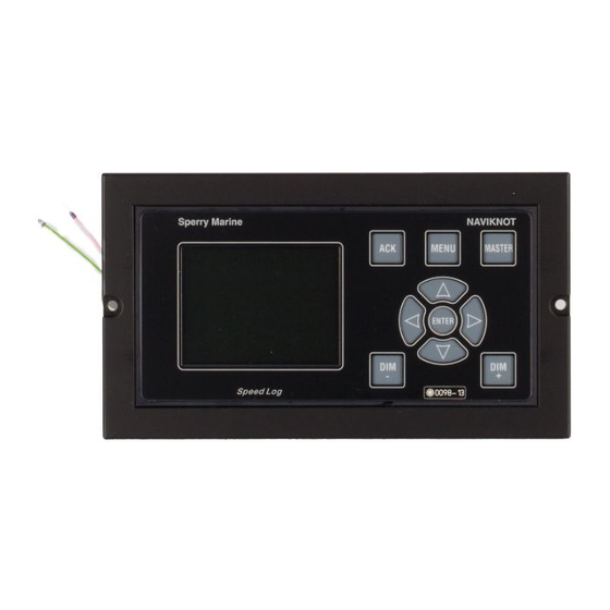
NAVIKNOT 600 SD 056353/J Chapter 2: Operation 2.1 Display and Operating Keys Figure 2-1: NAVIKNOT 600 SD operating unit NAVIKNOT MENU MASTER MUTE MASTER 600 SD NO ALERTS N.MILES DAILY ENTER 1234.56 TOTAL 123456.7 Main Display : shows one of five selectable pages, indicating –... -
Page 32: External Control Devices
Depending on the installation, external devices may be present to remotely control certain functions of the NAVIKNOT 600 SD: • The audible alert at the NAVIKNOT 600 SD may be muted from a remote device, e.g. a central alert panel. •... -
Page 33: Power-Up Sequence
NAVIKNOT 600 SD 056353/J 2.3 Power-up Sequence Operational Power-up Sequence The individual components of the NAVIKNOT system are not equipped with power switches. All devices start up simultaneously, as soon as supply power is applied to the system. Upon power up, the startup routine is executed: The startup screen is shown and a system test sequence is executed. -
Page 34: Power-Up Sequence With Software Mismatch
056353/J NAVIKNOT 600 SD Power-up Sequence with Software Mismatch CAUTION Risk of non-compliant System State / defective Alert Handling Software update of the NAVIKNOT EU at least to version 3.000 and of all installed CDUs at least to version 2.000 is mandatory for correct opera- tion and alert handling of the NAVIKNOT system. - Page 35 NAVIKNOT 600 SD 056353/J EU Software Mismatch: In case of EU software mismatch, SOFTWARE MISMATCH ! the adjacent screen is indicated. The operator is informed UPDATE OF EU SOFTWARE AT LEAST TO VERSION 3.000 IS MANDATORY ! regarding the mandatory soft-...
- Page 36 056353/J NAVIKNOT 600 SD Note In case of a CDU software mismatch, the NAVIKNOT EU recognizes the software mismatch and transmits a suitable alert message (alarm: CDU SW UPDATE REQUIRED / warning: Software mismatch) to an active CAM system. The alert message may become indicated at a connected CAM display.
-
Page 37: Display Indications In Normal Operational Mode
NAVIKNOT 600 SD 056353/J 2.4 Display Indications in Normal Operational Mode Main Display Pages In the normal operational mode, the CDU permanently displays one of the five selectable main display pages. Ground Speed (SOG) The main display shows the actual... - Page 38 056353/J NAVIKNOT 600 SD Docking Display The main display shows a graphical MASTER representation of the vessel, indi- 600 SD cating the actual longitudinal speed NO ALERTS over ground as well as the trans- verse ground speeds at the bow 123.45...
-
Page 39: Operating Status Indications
CAUTION Invalid speed and distance information in „MAN“ mode of operation In case of failure of the Doppler transducer, the NAVIKNOT 600 SD does not provide valid speed and distance information and the system needs to become operated in the alternative “MAN” mode of operation. -
Page 40: Requesting Master Control
056353/J NAVIKNOT 600 SD Water speed not calibrated When the sensor calibration table is 81&$ / 123456.7 empty or calibration has been switched off, the indication “UNCAL ” is shown in the bottom left corner of the speed display. 2.5 Requesting Master Control... -
Page 41: Adjusting The Display Brightness
1234.56 TOTAL 123456.7 Note The display brightness can only be adjusted in normal operational mode. The brightness setting is not retained between power-ups. The NAVIKNOT 600 SD always powers up at the second brightest level. Adjusting the display brightness 2-11... -
Page 42: Optional Functions
NAVIKNOT 600 SD automatically resets the watch alarm timer when- ever a key is pressed on the unit ('dead man alarm'). Should a watch alarm be given, press any key at the NAVIKNOT 600 SD to acknowledge the alarm and reset the watch alarm timer. -
Page 43: External Dimming
Via external pushbuttons, the same functionality is available as with the DIM+/DIM- keys at the CDU. External Dimming via Dimming Device The NAVIKNOT 600 SD Electronics Unit also possesses an input for serial data dimming commands from a connected central dimming device. -
Page 44: Operating Menu
056353/J NAVIKNOT 600 SD 2.8 Operating Menu The manual settings, user and service setup sub-menus are accessed through a multilevel operating menu. Entering and Quitting the Menu Mode From the normal operational MASTER mode, press MENU to enter 600 SD the menu mode. -
Page 45: Navigating The Menu
NAVIKNOT 600 SD 056353/J Navigating the Menu In the menu mode, the operator may navigate through the menu using the Right, Left, Up and Down arrow keys. Arrow symbols (>) to the MAIN MENU MAIN MENU right of the window indicate... -
Page 46: Selecting Parameter Settings
056353/J NAVIKNOT 600 SD Selecting Parameter Settings In a number of sub-menus, the operator is expected to select parameter settings from a list of available options. The available options and the current selection are indicated by different symbols: Radio buttons: Allow to select exactly one of the available options. -
Page 47: Caption For Selecting And Editing
NAVIKNOT 600 SD 056353/J Caption for Selecting and Editing Figure 2-2 shows the caption for the different selecting and editing sym- bols used in all menus and submenus. Figure 2-2: SERVICE SETUP 1 û Caption for choice, functionality of submenu 1... -
Page 48: Manual Settings Menu
CAUTION Invalid speed and distance information in „MAN“ mode of operation In case of failure of the Doppler transducer, the NAVIKNOT 600 SD does not provide valid speed and distance information and the system needs to become operated in the alternative “MAN” mode of operation. -
Page 49: Manual Settings - Overview
NAVIKNOT 600 SD 056353/J Manual Settings – Overview Figure 2-3: MAIN MENU Manual Settings MANUAL SETTINGS > > SPEED MODE STW > > water speed input mode SPEED MODE STW SENSOR > > SPEED MODE SOG > > ground speed input mode... -
Page 50: Manual Settings - Parameters
056353/J NAVIKNOT 600 SD Manual Settings – Parameters SPEED MODE STW Selects the input mode for water speed data. Settings: MAN (Manual) The actual speed value is entered manually. This setting may be activated only temporarily, to generate water speed output data in case of failure of the Doppler transducer or for testing. - Page 51 Sets the operating mode for SSD12 digital speed repeaters. While the SSD12 is now discontinued, existing units from the previously installed SRD 500 system may be operated with the NAVIKNOT 600 SD. The SSD12 Rep. Spd Sel setting is effective only if at least one group of RS-422 outputs has been configured for the SSD12 data format in the Service Setup.
-
Page 52: User Setup
056353/J NAVIKNOT 600 SD 2.10 User Setup The User Setup menu provides access to settings which the operator may need to alter only occasionally. 2-22 User Setup... -
Page 53: User Setup - Overview
NAVIKNOT 600 SD 056353/J User Setup – Overview Figure 2-4: MAIN MENU User Setup USER SETUP > > DAMP. TIME DISPLAY > > damping time constant DAMP . TIME DISPLAY for speed display RANGE: 0 – 60 SEC > >... - Page 54 056353/J NAVIKNOT 600 SD Figure 2-5: contd. from previous page User Setup (contd.) > > SCALE > > speed display units SCALE SPEED SCALE FT/S DOCKING SPEED SCALE FT/S SOFTWARE VERSION NN.NN > > NAVIKNOT EU SOFTWARE VERSION software version...
-
Page 55: User Setup - Parameters
NAVIKNOT 600 SD 056353/J User Setup – Parameters DAMP . (Damping) TIME DISDPLAY Sets the damping time constant for the speed indication at the speed display. The higher the time constant, the stronger sudden peaks of the actual speed indication will be damped. - Page 56 056353/J NAVIKNOT 600 SD RESET DAILY MILES Sets the reset flag for the daily miles counters. If the reset flag is set, the daily miles counters are reset to zero as soon as the User Setup is quit. Settings: ON (option checked)
- Page 57 NAVIKNOT 600 SD 056353/J TOTAL MILES COUNTER WATER START VALUE Sets the water speed total miles counter to a desired start value. Settings: RANGE: 0.0 – 999999.9 NM GROUND START VALUE Sets the ground speed total miles counter to a desired start value.
- Page 58 056353/J NAVIKNOT 600 SD DOCKING SPEED SCALE Unit of measure for the docking display page Settings: Speed is displayed in knots. Speed is displayed in metres per second. FT/S Speed is displayed in feet per second. SOFTWARE VERSION Displays the software version of the NAVIKNOT Electronics Unit.
-
Page 59: Chapter 3: Alerts
NAVIKNOT 600 SD 056353/J Chapter 3: Alerts 3.1 Alert Management Preliminaries CAUTION Risk of non-compliant System State / defective Alert Handling Software update of the NAVIKNOT EU at least to version 3.000 and of all installed CDUs at least to version 2.000 is mandatory for correct opera- tion and alert handling of the NAVIKNOT system. - Page 60 Note At the time of writing, only the alarm „SW mismatch“ exists for the NAVIKNOT 600 SD system when ALF-ALC-ARC/ACN are selected as NMEA messages (BAMS). The alarm cannot be indicated at the NAVIKNOT CDU and is only trans- mitted to an active CAM system.
-
Page 61: Alert Indication
NAVIKNOT 600 SD 056353/J 3.2 Alert Indication Audible Alert Indication Single Beep: Invalid Action A single short beep indicates that the operator attempted to carry out an invalid action. This is the case e.g. if the operator attempts to enter the menu from a remote unit. -
Page 62: Visual Alert Indication (Alr/Ack)
056353/J NAVIKNOT 600 SD Visual Alert Indication (ALR/ACK) Note The NAVIKNOT alert management with NMEA message selection ALR/ACK differentiates between alarms and warnings as alert priorities. The alert priority of the topmost alert and the total number of active alerts are indicated in the alert display area of the main display. - Page 63 NAVIKNOT 600 SD 056353/J Acknowledged: The operator has acknowledged the alarm but the error cause of the alarm is still active. The acknowledged alarm message ALARM is shown with white text on a solid 2 ALERTS red background (not flashing).
-
Page 64: Visual Alert Indication (Alf-Alc-Arc/Acn)
Note At the time of writing, only the alarm „SW mismatch“ exists for the NAVIKNOT 600 SD system when ALF-ALC-ARC/ACN are selected as NMEA messages (BAMS). The alarm cannot be indicated at the NAVIKNOT CDU and is only trans- mitted to an active CAM system. - Page 65 NAVIKNOT 600 SD 056353/J Acknowledged: The operator has acknowledged the warning but the error cause of the warning is still active. The acknowledged warning is shown with white text on a solid WARNING yellowish orange background (not 2 ALERTS flashing).
-
Page 66: Muting Alerts
056353/J NAVIKNOT 600 SD 3.3 Muting Alerts Local Alert Mute To mute (silence) a pending alert at the NAVIKNOT 600 SD CDU: From the main speed display page, press ACK MUTE. The audible alert indication is ALARM 2 ALERTS muted (silenced). -
Page 67: External Alert Mute
2 ALERTS The alert remains in the pending alert state „ACTIVE SILENCED“ , ext. mute facility until it either: – is locally acknowledged at the NAVIKNOT 600 SD CDU ALARM (alert state ACTIVE 2 ALERTS ACKNOWLEDGED), – gets rectified (alert state... -
Page 68: Acknowledgement Of Alerts (Alr/Ack)
056353/J NAVIKNOT 600 SD 3.4 Acknowledgement of Alerts (ALR/ACK) Note From CDU and EU software version 2.100 on, acknowledgement of alerts is possible from the alert main display page only. Previous EU software versions allowed alert acknowledgement from any display page without previous mute, as now considered not compliant. -
Page 69: Acknowledgement Of Alarms
NAVIKNOT 600 SD 056353/J Acknowledgement of Alarms To acknowledge a pending alarm at the NAVIKNOT 600 SD CDU: A pending alarm is displayed flash- MASTER ing in the alert display area of the 600 SD speed main display page. ALARM... - Page 70 056353/J NAVIKNOT 600 SD Alert List main display page ACTIVE UNACKNOWLEDGED MASTER ALERT LIST as respective alert state is shown at 600 SD the bottom of the alert page. < (1/2) > ALARM NO: 50 SRD TIMEOUT The index number of the currently...
- Page 71 NAVIKNOT 600 SD 056353/J RECTIFIED UNACKNOWLEDGED MASTER ALERT LIST as respective alert state is shown at 600 SD the bottom of the alert page, if an < (1/2) > unacknowledged active alert gets ALARM NO: 50 SRD TIMEOUT inactive (rectified).
- Page 72 056353/J NAVIKNOT 600 SD If an acknowledged alert gets inac- tive, the alert will immediately dis- appear from the alert list. RECTIFIED ACKNOWLEDGED as alert state is NEVER indicated. The next topmost alert priority will be indicated, in case of other pending alert priorities.
-
Page 73: Acknowledgement Of Warnings
NAVIKNOT 600 SD 056353/J Acknowledgement of Warnings To acknowledge a pending warning at the NAVIKNOT 600 SD CDU: A pending warning is displayed MASTER flashing in the alert display area of 600 SD the speed main display page. WARNING 2 ALERTS N.MILES... - Page 74 056353/J NAVIKNOT 600 SD Alert List main display page ACTIVE UNACKNOWLEDGED MASTER ALERT LIST as respective alert state is shown at 600 SD the bottom of the alert page. < (1/2) > WARNING NO: 75 AUTO HDG SWITCHOVER The index number of the currently...
- Page 75 NAVIKNOT 600 SD 056353/J RECTIFIED UNACKNOWLEDGED MASTER ALERT LIST as respective alert state is shown at 600 SD the bottom of the alert page, if an < (1/2) > unacknowledged active alert gets WARNING NO: 75 AUTO HDG SWITCHOVER inactive (rectified).
- Page 76 056353/J NAVIKNOT 600 SD Note In case of an “EU timeout” alert, dashes will appear in the CDUs speed and distance displays. The “EU timeout” will be shown as the only alert condition, as the CDU receives no messages from the electronics unit when communication is lost.
-
Page 77: Acknowledgement Of Alerts (Alf-Alc-Arc/Acn)
Note At the time of writing, only the alarm „SW mismatch“ exists for the NAVIKNOT 600 SD system when ALF-ALC-ARC/ACN are selected as NMEA messages (BAMS). The alarm cannot be indicated at the NAVIKNOT CDU and is only trans- mitted to an active CAM system. - Page 78 056353/J NAVIKNOT 600 SD Note NAVIKNOT does not keep a history of past (rectified acknowledged) alerts. 3-20 Acknowledgement of Alerts (ALF-ALC-ARC/ACN)
-
Page 79: Acknowledgement Of Warnings
NAVIKNOT 600 SD 056353/J Acknowledgement of Warnings To acknowledge a pending warning at the NAVIKNOT 600 SD CDU: A pending warning is displayed MASTER flashing in the alert display area of 600 SD the speed main display page. WARNING 2 ALERTS N.MILES... - Page 80 056353/J NAVIKNOT 600 SD Alert List main display page ACTIVE UNACKNOWLEDGED MASTER ALERT LIST as respective alert state is shown at 600 SD the bottom of the alert page. < (1/2) > WARNING NO: 3008 Lost STW The index number of the currently...
- Page 81 NAVIKNOT 600 SD 056353/J RECTIFIED UNACKNOWLEDGED MASTER ALERT LIST as respective alert state is shown at 600 SD the bottom of the alert page, if an < (1/2) > unacknowledged active alert gets WARNING NO: 3008 Lost STW inactive (rectified).
- Page 82 056353/J NAVIKNOT 600 SD Note In case of an “EU timeout” alert, dashes will appear in the CDUs speed and distance displays. The “EU timeout” will be shown as the only alert condition, as the CDU receives no messages from the electronics unit when communication is lost.
-
Page 83: Cautions
NAVIKNOT 600 SD 056353/J Cautions A pending caution has always the alert state „ACTIVE“ and does there- fore not need to become acknowledged. A pending caution is displayed in MASTER the alert display area of the speed 600 SD main display page with black text... -
Page 84: Serial Data Alert Management
The $--ALR and $--ACK sentences are implemented as follows: • When no alert conditions are present, the NAVIKNOT 600 SD trans- mits a “no alerts” message as recommended per IEC 80/520/INF , once per second. This is an $--ALR sentence with null fields for the alarm code and description. -
Page 85: Alert Handling (Alf-Alc-Arc/Acn)
The $--ALF, $--ALC, $--ARC and $--ACN sentences are implemented as follows: • When no alert conditions are present, the NAVIKNOT 600 SD trans- mits a “no alerts” ALC message every 25 seconds, as requested per IEC 61162-1. This is an $--ALC sentence with null fields for the alert entries. -
Page 86: Alert Codes And Messages
If NMEA messages ALR/ACK are selected for alert management, the NAVIKNOT alerts have no IEC standard categorization. Table 3-1: Alert Alert Alert Message Cause Corrective Action NAVIKNOT 600 SD alerts Type (ALR/ACK none WAITING FOR Communica- Check operation of MAIN UNIT tion between the electronics unit;... - Page 87 NAVIKNOT 600 SD 056353/J Alert Alert Alert Message Cause Corrective Action Type GPS INIT Initialisation of Restart system ERROR antenna failed. SRD TIMEOUT Transducer pro- Check that the pre- tocol detection amplifier is operat- failed ing; check that protocol PREAMP D.
- Page 88 056353/J NAVIKNOT 600 SD Alert Alert Alert Message Cause Corrective Action Type TRANS. SPD Loss of or inva- Check cabling of TIMEOUT lid GPS speed satellite antenna data. unit. Satellite antenna unit is defective, if error persists. Power down the system.
- Page 89 NAVIKNOT 600 SD 056353/J Alert Alert Alert Message Cause Corrective Action Type EU TIMEOUT Communica- Check basic opera- tion lost tion of the electron- between elec- ics unit (valid tronics unit and output generated at serial data / ana- logue outputs);...
-
Page 90: Alerts (Alf-Alc-Arc/Acn) / Prop. Bam Alerts Active
IDs (30xx) are incremented by „10000“, making this NAVIKNOT alerts PROPRIETARY. Table 3-2: Alert Alert Alert Alert Alert Corrective Action NAVIKNOT 600 SD alerts Inst. Prio Title Description (ALF-ALC-ARC-ACN / SW mis- CDU software Update CDU soft- prop. - Page 91 NAVIKNOT 600 SD 056353/J Alert Alert Alert Alert Alert Corrective Action Inst. Prio Title Description 13062* 3 Sensor No water Error is cleared fault speed sensor once transducer found protocol has been determined. If error persists, check pre- amplifier D for proper operation.
-
Page 92: Alerts (Alf-Alc-Arc/Acn) / Prop. Bam Alerts Inactive
80/857/CDV 2017-9-15 supposed to become released as IEC 62923-2. This is therefore NOT CONFORM at the time of writing. Table 3-3: Alert Alert Alert Alert Alert Corrective Action NAVIKNOT 600 SD alerts Inst. Prio Title Description (ALF-ALC-ARC-ACN / SW mis- CDU software Update CDU soft- prop. - Page 93 NAVIKNOT 600 SD 056353/J Alert Alert Alert Alert Alert Corrective Action Inst. Prio Title Description 3062 Sensor No water Error is cleared fault speed sensor once transducer found protocol has been determined. If error persists, check pre- amplifier D for proper operation.
- Page 94 056353/J NAVIKNOT 600 SD 3-36 Alert Codes and Messages...
-
Page 95: Chapter 4: Scheduled Maintenance
Chapter 4: Scheduled Maintenance 4.1 Maintenance by Shipboard Personnel NAVIKNOT Electronics Unit, CDU and Antenna Unit The electronic components of the NAVIKNOT 600 SD system are solid- state devices and contain no consumable parts. Therefore, no set main- tenance schedule is required. - Page 96 056353/J NAVIKNOT 600 SD Maintenance by Shipboard Personnel...
-
Page 97: Chapter 5: Installation
GPS antennas (bow/stern or stbd./port antennas), mounted on a beam-shaped support. Therefore, it is critical for the function of the NAVIKNOT 600 SD that the antenna unit is installed at the best possible location. The two main factors which may degrade the performance of the anten- nas are shadowing of the GPS signals and multipath reflections. - Page 98 056353/J NAVIKNOT 600 SD When choosing the antenna location, observe the guidelines below to minimize the effects of signal shading, multipath reflections and inter- ference. • If a mast or other object obstructs the all-round view, install the antenna unit at a distance of at least ten times the object’s width.
- Page 99 NAVIKNOT 600 SD 056353/J When installing the antenna unit, the cable assembly must be connected to the cable ends from the bow and stern antenna. After connecting the cables, secure them to the support with the wire clips and seal the cable connections with the self-fusing tape provided.
-
Page 100: Doppler Transducer And Preamplifier D
The preamplifier D, type 5005, may be installed at the same time as the sensor or later, together with the other electronic components of the NAVIKNOT 600 SD system. NAVIKNOT Electronics Unit The electronics unit is to be installed at a protected location. In most cases, it will be mounted in the vicinity of the master CDU. -
Page 101: Control And Display Units
NAVIKNOT 600 SD 056353/J Control and Display Units Console Mounting 3x1 CDU (main or remote) To mount a NAVIKNOT 3x1 CDU, type 5002, directly in a console panel (without console frame), a panel cutout is required as shown in drawing 5002-0112-02 (see Appendix). -
Page 102: Electrical Installation
Preamplifier D Configuration The preamplifier D, as delivered by Sperry Marine, will be preconfigured for use within the NAVIKNOT system. However, the setting of configura- tion jumpers and dip-switch contacts as well as the transmit power adjustment should be checked prior to first-time operation. -
Page 103: Initial System Configuration
NAVIKNOT 600 SD 056353/J If installation-specific connection diagrams have been provided for a given system, these supersede any connection information contained in standard connection diagrams. If wiring up according to standard connection diagrams, make sure beforehand that all data and signals to receive from or transmit to exter- nal equipment comply to the NAVIKNOT Electronics Unit interface. - Page 104 056353/J NAVIKNOT 600 SD CDU Service Setup – Overview Figure 5-8: SERVICE SETUP CDU Service Setup > > CDU ID > > this CDU's local ID CDU ID RANGE: 0 – 9 > > DIMMING > > settings for DIMMING...
- Page 105 NAVIKNOT 600 SD 056353/J CDU Service Setup – Parameters CDU ID Sets the CDU’s local ID. The ID serves to identify the individual CDUs in systems where one or more remote CDUs are installed. In case more than one CDU is installed, the electronics unit uses the ID to keep track of which CDU is currently assigned master command.
- Page 106 056353/J NAVIKNOT 600 SD DIM VALUES (MIN VALUE - VALUE 2–7 - MAX VALUE) Maps the ordered brightness setting as read from the serial dim command to the CDU’s nine discrete brightness levels. CDU type 5001 CDU type 5002 RANGE: 00 – 999 RANGE: 00 –...
-
Page 107: Configuring System Parameters
NAVIKNOT 600 SD system are available through the Service Setup. After the initial system configuration, note all settings in the NAVIKNOT 600 SD system setup table (see Appendix). Send one copy of the filled-out table to Sperry Marine for inclusion in the ship’s file. - Page 108 056353/J NAVIKNOT 600 SD 5-12 Initial System Configuration...
-
Page 109: Chapter 6: System Configuration
Chapter 6: System Configuration 6.1 Service Setup Menu The Service Setup menu provides access to the system parameters which configure the NAVIKNOT 600 SD according to the requirements of the installation at hand. Setup Access Code To prevent inadvertent or unauthorized changes to the system configu- ration, setup menus which are to be accessed by service personnel only are protected by access codes. -
Page 110: Service-Setup - Overview
056353/J NAVIKNOT 600 SD Service-Setup – Overview Figure 6-1: SERVICE SETUP Page 1 Service Setup, page 1 > > NEXT PAGE (2) > > skip to page 2 > > ANALOG OUTPUT > > settings for analogue ANALOG OUTPUT speed outputs... - Page 111 NAVIKNOT 600 SD 056353/J Figure 6-2: contd. from previous page Service Setup, page 1 (contd) > > PULSE OUTPUT 1-3 > > PULSE / NM settings for pulse outputs 1-3 PULSE / NM 1–3 10 PULSE/NM 100 PULSE/NM 200 PULSE/NM...
- Page 112 056353/J NAVIKNOT 600 SD Figure 6-3: contd. from previous page Service Setup, page 1 (contd) > > RS422 OUTPUT 1-3 > > settings for RS-422 outputs RS422 OUTPUT 1–3 group 1 (outp.1-3) PROTOCOL NMEA SSD12 MESSAGES NMEA 1–3 VLW extended...
- Page 113 NAVIKNOT 600 SD 056353/J Figure 6-4: contd. from previous page Service Setup, page 1 (contd) > > NMEA INPUT 1 > > settings for NMEA input 1 NMEA INPUT 1 MESSAGES NMEA INP . 1 PPLAI BAUDRATE NMEA INP . 1...
- Page 114 056353/J NAVIKNOT 600 SD Figure 6-5: SERVICE SETUP Page 2 Service Setup, page 2 > > NEXT PAGE (1) > > skip to page 1 > > SYSTEM TYPE > > system type configuration SYSTEM TYPE NAVIKNOT 600SD type must be set to 600SD >...
- Page 115 NAVIKNOT 600 SD 056353/J Figure 6-6: contd. from previous page Service Setup, page 2 (contd) > > CALIBRATION > > sensor calibration settings CALIBRATION CAL. TABLE ON access calibration table CALIBRATION TABLE entries CAL. TABLE CAL.NO UNCAL SPEED -- --...
- Page 116 056353/J NAVIKNOT 600 SD Figure 6-7: contd. from Service Setup, previous page page 2 (contd) > > NAVIKNOT GPS SETUP > > NAVIKNOT GPS SETUP access to satellite setup access setup menu of the new satellite PCB, type 5003-AA (not supported by old NAVIKNOT 600S,...
-
Page 117: Service Setup - Parameters
NAVIKNOT 600 SD 056353/J Service Setup – Parameters ANALOG OUTPUT Configures the analogue speed outputs (voltage and current output). SOURCE Selects the data source for the analogue outputs. Setting: The outputs provide the actual speed over ground The outputs provide the actual speed through the water... - Page 118 056353/J NAVIKNOT 600 SD VOLTAGE Configures the analogue output voltage range. The output voltage range is defined by two pairs of values: The minimum speed and associated minimum voltage determine the lower limit of the output range, while the maximum speed and associ- ated maximum voltage define its upper limit.
- Page 119 NAVIKNOT 600 SD 056353/J CURRENT Configures the analogue output current range. The output current range is defined by two pairs of values: The minimum speed and associated minimum current determine the lower limit of the output range, while the maximum speed and associ- ated maximum current define its upper limit.
- Page 120 This signal, a 100 ms pulse, is used to mute the audible alert indication at a central alert facility when the respective alert is acknowledged locally at the NAVIKNOT 600 SD CDU. PULSE OUTPUT 1–3 PULSE / NM 1-3 Configures group 1 of the pulse outputs (outputs 1 –...
- Page 121 NAVIKNOT 600 SD 056353/J PULSE OUTPUT 4–5 PULSE / NM 4-5 Configures group 2 of the pulse outputs (outputs 4– 5). Selects the output pulse frequency. Settings: 10 PULSE/NM The output delivers 10 pulses per nautical mile. 100 PULSE/NM The output delivers 100 pulses per nautical mile.
- Page 122 The output delivers 20000 pulses per nautical mile. MUTE RELAY When an alert is acknowledged locally at the NAVIKNOT 600 SD CDU, the output delivers a pulse to mute the audible alert indication at a central alert facility. SOURCE PULSE 6 Selects the data source for pulse output 6.
- Page 123 NAVIKNOT 600 SD 056353/J Settings: NMEA NMEA messages are preselected. The MESSAGES NMEA 1-3 and BAUDRATE NMEA 1-3 submenus are indicated and available. SSD12 SSD12 message is preselected. Longitudinal and transverse water speeds are transmitted using the proprietary SSD12 repeater format.
- Page 124 MESSAGES NMEA 1-3 Selects the NMEA sentences to transmit. If the NAVIKNOT 600 SD cannot provide valid data for an NMEA sen- tence field, a null field (empty field) is sent. Status fields for invalid or unknown data are marked invalid (“V“). Other sentences than those described below must not be activated for the NAVIKNOT 600 SD.
- Page 125 NAVIKNOT 600 SD 056353/J CAM Interface Settings Note NAVIKNOT complies with the statutory requirements regarding a serial interface for the alert management (alert presentation and acknowledge- ment) by a Central Alert Management System (CAM) following IEC 61162 (NMEA 0183) and MSC.302(87) (BAMS).
- Page 126 056353/J NAVIKNOT 600 SD RS422 OUTPUT 4–6 Configures group 1 of the RS-422 serial data outputs (outputs 4–6). PROTOCOL Selects the protocol and preselects the message and baudrate settings of the RS422 output 1-3. Settings: NMEA NMEA messages are preselected.
- Page 127 MESSAGES NMEA 4-6 Selects the NMEA sentences to transmit. If the NAVIKNOT 600 SD cannot provide valid data for an NMEA sen- tence field, a null field (empty field) is sent. Status fields for invalid or unknown data are marked invalid (“V“). Other sentences than those described below must not be activated for the NAVIKNOT 600 SD.
- Page 128 056353/J NAVIKNOT 600 SD CAM Interface Settings Note NAVIKNOT complies with the statutory requirements regarding a serial interface for the alert management (alert presentation and acknowledge- ment) by a Central Alert Management System (CAM) following IEC 61162 (NMEA 0183) and MSC.302(87) (BAMS).
- Page 129 NAVIKNOT 600 SD 056353/J NMEA INPUT 1 Configures the NMEA input 1. MESSAGES NMEA INP . (Input) 1 Selects the NMEA sentences to receive. Settings: Enables the input to receive true heading data from the $--HDT sentence. Selecting this option lets the system ignore heading data from the satellite PCB in favour of the external data.
- Page 130 056353/J NAVIKNOT 600 SD CAM Interface Settings Note NAVIKNOT complies with the statutory requirements regarding a serial interface for the alert management (alert presentation and acknowledge- ment) by a Central Alert Management System (CAM) following IEC 61162 (NMEA 0183) and MSC.302(87) (BAMS).
- Page 131 NAVIKNOT 600 SD 056353/J NMEA INPUT 2 Configures the NMEA input 2. MESSAGES NMEA INP . (Input) 2 Selects the NMEA sentences to receive. Settings: Enables the input to receive true heading data from the $--HDT sentence. Selecting this option lets the system ignore heading data from the satellite PCB in favour of the external data.
- Page 132 056353/J NAVIKNOT 600 SD CAM Interface Settings Note NAVIKNOT complies with the statutory requirements regarding a serial interface for the alert management (alert presentation and acknowledge- ment) by a Central Alert Management System (CAM) following IEC 61162 (NMEA 0183) and MSC.302(87) (BAMS).
- Page 133 LON. (Longitudinal) SPEED MAX RANGE: -99.9 – 99.9 KN Default value: +60.0 Note Normally, it is not required to alter the speed filter default settings. Access this menu only if instructed to do so by Sperry Marine. Service Setup Menu 6-25...
- Page 134 056353/J NAVIKNOT 600 SD SYSTEM TYPE Configures the NAVIKNOT system type. For the NAVIKNOT 600 SD, the type must be set to 600SD; all other options are to be ignored. Settings: NAVIKNOT 600 SD SENSOR POLARITY Sets the polarity in accordance to the mounting direction of the sensor.
- Page 135 NAVIKNOT 600 SD 056353/J RELAY SPEED LIMIT Selects the data source for the relay speed limit outputs and sets the thresholds for the speed limit relay output. SOURCE Selects the data source for the relay speed limit outputs. Setting: The outputs provide the actual speed over ground...
- Page 136 056353/J NAVIKNOT 600 SD Setting thresholds for speed limit relay output Setting the lower and/or upper switching thresholds: The speed limit relay output provides a status signal to external equip- ment, to indicate that the actual speed has exceeded or fallen below a set threshold.
- Page 137 Activates or de-activates the calibration table. Settings: ON (option checked) Calibration is active. The NAVIKNOT 600 SD corrects the data received from the preamplifier according to the calibra- tion table. The resulting calibrated speed is displayed and transmitted at the data outputs.
- Page 138 056353/J NAVIKNOT 600 SD ZERO POINT Sets the calibration zero point (correction value at a true speed of 0 kn). MAN (Manual) CALIBRATION Sets the calibration zero point by manual calibration. Settings: TRUE SPEED nn.n KN True speed value indication.
- Page 139 NAVIKNOT 600 SD 056353/J ONE WAY TRIAL RUN Accesses the sub-menu for conducting a one-way calibration trial run. Settings: TIME 00:00 S Indication of trial run time. SPEED nn.nn KN Indication of trial run speed. Settings: refer to chapter 7, “Doppler Transducer Calibration” , for a...
- Page 140 056353/J NAVIKNOT 600 SD ANTENNA DISTANCES Configures the geometrical parameters of the GPS antenna location. Note The Antenna Distances are required for correct calculation of the bow and stern transverse speeds shown in the docking display page. The exactness of the inserted distances is essential for the docking speed accuracy.
- Page 141 PREAMPL D SETUP Calls up a setup menu to test and troubleshoot the Doppler preamplifier. This option is currently not officially supported. Access this menu only if instructed to do so by Sperry Marine. TEST MODE Activates the Doppler preamplifier test mode.
- Page 142 056353/J NAVIKNOT 600 SD PROP . (Proprietary) BAM ALERTS Activates or inactivates the proprietary BAM alert setting. Settings: ON (option checked) The proprietary BAM alert setting is activated. OFF (option unchecked) The proprietary BAM alert setting is inactivated. Note In case the proprietary BAM alert setting is ACTIVATED and the NMEA Messages ALF-ALC-ARC/ACN (BAMS) are selected for the alert management, all four digit alert IDs (30xx) are incremented by „10000“,...
-
Page 143: Gps Setup
NAVIKNOT 600 SD setup. Note Some of the available GPS configuration options do not apply to the NAVIKNOT 600 SD system. These must be left at the factory default set- tings as noted in the GPS setup descriptions below. GPS Setup Operation (solid arrow): Indicates the current cursor position on the screen (equivalent to angle bracket symbol in the NAVIKNOT 600 SD setup). -
Page 144: Gps Setup - Overview
056353/J NAVIKNOT 600 SD GPS Setup – Overview Figure 6-8: *366(783(;7(51$/ GPS Setup pages 7230(1 +HDGLQJ6HOHFWLR Heading Selection $OLJQDQG&DOLEUDW +HDGLQJ6HOHFWLR * 3 6 must be 2 1 and active * 3 6 É 0 $ * must be 2 ) ) -
Page 145: Gps Setup - Parameters
Configures the heading sources available to the satellite PCB. The currently active source provides the heading sent from the satellite PCB to the NAVIKNOT 600 SD electronics unit. Only the GPS source may be made active, i.e. the satellite PCB must always determine the vessel’s heading internally from the two GPS... - Page 146 Sets the correction values (“deltas”) to compensate for existing offsets of the heading sources relative to the vessel’s fore-and-aft line. As only the GPS source is used within the NAVIKNOT 600 SD system, a delta value must be entered for the GPS source only. This compensates for misalignment of the GPS antenna support with the vessel’s fore-and-...
- Page 147 Calibrates the magnetic heading sensor on the satellite PCB. The magnetic heading sensor contained on the satellite PCB is not suita- ble for use within the NAVIKNOT 600 SD system. Therefore it must not be calibrated. Do not carry out the Mag at Sea Cal. procedure. Leaving the sensor in the uncalibrated state will prevent it from being activated by accident.
- Page 148 056353/J NAVIKNOT 600 SD 6-40 GPS Setup...
-
Page 149: Chapter 7: Doppler Transducer Calibration
NAVIKNOT 600 SD 056353/J Chapter 7: Doppler Transducer Calibration Once the NAVIKNOT 600 SD system has been installed and the basic configuration carried out, a calibration of the Doppler transducer must be proceeded. During the calibration procedure, the speed measures of... - Page 150 056353/J NAVIKNOT 600 SD Figure 7-1: Effect of calibration table entries zero point (true water speed = 0.0 kn) raw data (input) raw data (input) intermediate cal. highest cal. table entry table entry raw data (input) raw data (input) calibration table empty: linear transducer characteristic assumed;...
-
Page 151: Editing The Calibration Table Directly
NAVIKNOT 600 SD 056353/J Editing the Calibration Table Directly To add, edit or delete calibration points directly, go to page 2 of the Service Setup and select the Calibration | Cal.Table sub-menu. The data stored at calibration point no. 00 is shown (dashes will appear if the table is empty). -
Page 152: Zero Point Calibration
056353/J NAVIKNOT 600 SD Zero Point Calibration Before any entries for non-zero speeds are stored in the calibration table or calibration trial runs are conducted, the zero point calibration should be carried out. The “zero point” refers to the calibration table entry which holds the uncalibrated (“raw“) speed value corresponding to a true water speed of... - Page 153 NAVIKNOT 600 SD 056353/J Automatic Entry With the automatic entry method, the required zero point setting is determined automatically. Automatic entry may only be used when the vessel is stationary in waters free of current, i.e., if the actual water speed is known to be zero.
-
Page 154: Calibration By Trial Runs
However, as the NAVIKNOT 600 SD obtains the vessel’s current position from the satellite PCB, it is equally acceptable to start the run clock at a given point in time and to stop it as soon as a distance of at least one mile has been traversed. - Page 155 NAVIKNOT 600 SD 056353/J Two Way Trial Run Note During a two way trial run, the vessel’s heading during runs A and B should ideally be parallel to the direction of the effective drift, as the drift component perpendicular to the heading cannot be compensated for.
- Page 156 056353/J NAVIKNOT 600 SD The display again indicates the run distance, the average uncali- brated speed, the true speed over ground and the calculated calibra- tion value. 10. Press ENTER to store the run parameters. The Two Way Trial Run sub-menu is quit automatically.
- Page 157 NAVIKNOT 600 SD 056353/J One Way Trial Run Note In a one way trial run, any drift due to wind and/or current will adversely affect the calibration. Conducting a one way trial run in the presence of drift, may degrade instead of improve the speed accuracy.
- Page 158 056353/J NAVIKNOT 600 SD 7-10 Doppler Transducer Calibration...
-
Page 159: Chapter 8: Troubleshooting
8.1 NAVIKNOT Electronics Unit and CDU(s) The NAVIKNOT 600 SD electronics unit and the CDU are complex elec- tronic devices. In case of malfunction, it would neither be practical nor economical to carry out troubleshooting and servicing in the field down to the level of individual circuit components. -
Page 160: Location Of Parts On The Processor Pcb
Location of Parts on the Processor PCB Figure 8-1 below shows the locations of exchangeable components, connectors and diagnostic LED indicators of the processor PCB in the NAVIKNOT 600 SD electronics unit. Figure 8-1: Location of parts on the processor PCB... -
Page 161: Exchangeable Components, Processor Pcb
NAVIKNOT 600 SD 056353/J Exchangeable Components, Processor PCB Table 8-1: Component Name and Function Exchangeable components on the Flashboard (flash-memory card), processor PCB pre-programmed with system software IC 2; quad RS-422 output driver IC; drives serial data RS-422 outputs 1 to 3 IC 14;... -
Page 162: Diagnostic Leds, Processor Pcb
056353/J NAVIKNOT 600 SD Diagnostic LEDs, Processor PCB As an aid in troubleshooting, a number of diagnostic LED indicators are provided on the Electronics Unit PCB. These indicate the presence of supply voltages, activities on the serial data I/O lines and the current states of the status I/O ports. -
Page 163: Location Of Parts On The Satellite Pcb
Location of Parts on the Satellite PCB Figure 8-2 below shows the locations of relevant connectors, diagnostic LED indicators and the power switch of the satellite PCB inside the NAVIKNOT 600 SD electronics unit. Figure 8-2: Location of parts on the... -
Page 164: Connectors And Power Switch, Satellite Pcb
056353/J NAVIKNOT 600 SD Connectors and Power Switch, Satellite PCB Table 8-4: Function Connnectors and 24 VDC supply power in from processor PCB; power switch on the factory prewired: satellite PCB satellite PCB processor PCB J 1.1 – TB 1.3 J 1.2... -
Page 165: Maintenance Menu 1
NAVIKNOT 600 SD 056353/J 8.2 Maintenance Menu 1 The Maintenance Menu 1 provides several control settings for the sen- sor status, views the error list, gives access to diagnostic menus of the EU and allows a restart of the EU. -
Page 166: Maintenance Menu 1 - Overview
056353/J NAVIKNOT 600 SD Maintenance Menu 1 – Overview Figure 8-3: MAINTENANCE Maintenance Menu 1 > > EU VERSIONS > > hard-/software version IDs EU VERSIONS (read-only) EU HARDWARE hardware version ID EU SOFTWARE software version ID EU SW BUILD NO... - Page 167 NAVIKNOT 600 SD 056353/J Figure 8-4: contd. from previous page Maintenance Menu 1 (contd.) > > ERROR LIST > > internal error record ERROR LIST view list of recorded errors; ENTER-key clears all errors from list > > IN/OUT MONITOR >...
-
Page 168: Maintenance Menu 1 - Parameters
056353/J NAVIKNOT 600 SD Maintenance Menu 1 – Parameters EU VERSIONS Displays the hardware/software versions ID of the NAVIKNOT Electron- ics Unit. Settings: EU HARDWARE The hardware version ID is read-only. EU SOFTWARE The software version ID is read-only. EU SW BUILD NO The EU software build number is read-only. - Page 169 NAVIKNOT 600 SD 056353/J OPERATION COUNTER Displays the diagnostic counters (read only). Settings: WORKING HRS (Hours) Displays total system working hours. POWER UP’S Number of system resets. WDOG (Watchdog) RESETS Number of watchdog resets. ERROR LIST Displays the internal error record.
-
Page 170: Maintenance Menu 2
056353/J NAVIKNOT 600 SD 8.3 Maintenance Menu 2 The Maintenance Menu 2 provides control settings for the CDU status and allows a restart of the CDU. The Maintenance Menu 2 permits as well menu functions for the GPS antennae and the GPS satellites (antenna view). -
Page 171: Maintenance Menu 2 - Overview
NAVIKNOT 600 SD 056353/J Maintenance Menu 2 – Overview Figure 8-5: MAINTENANCE Maintenance Menu 2 > > CDU VERSIONS > > hard-/software version IDs CDU VERSIONS (read-only) CDU HARDWARE hardware version ID CDU SOFTWARE software version ID CDU SW BUILD NO... - Page 172 056353/J NAVIKNOT 600 SD Figure 8-6: contd. from previous page Maintenance Menu 2 (contd.) > > RESTART CDU CDU restart flag RESTART CDU check to restart CDU when maintenance menu is quit > > FACTORY SETTINGS factory settings restore flag...
-
Page 173: Maintenance Menu 2 - Parameters
NAVIKNOT 600 SD 056353/J Maintenance Menu 2 – Parameters CDU VERSIONS Displays the hardware/software versions ID of the NAVIKNOT CDU. Settings: CDU HARDWARE The hardware version ID is read-only. CDU SOFTWARE The software version ID is read-only. CDU SW BUILD NO The CDU software build number is read-only. -
Page 174: Doppler Transducer And Preamplifier D
056353/J NAVIKNOT 600 SD 8.4 Doppler Transducer and Preamplifier D Failure to receive valid speed data from the preamplifier D, resulting in a “SRD Timeout” or “Preamp D Timeout” alarm, may be caused by a mechanical or electrical defect in the transducer or by a defective pre- amplifier. -
Page 175: Chapter 9: Corrective Maintenance
The NAVIKNOT CDU and the PCBs inside the NAVIKNOT electronics unit are generally not field-serviceable on the component level. Defective devices must be sent back to Sperry Marine for repair. The only corrective maintenance procedures which may be performed by field service personnel are updates of the system software in the electronics unit and/or CDU(s). -
Page 176: Cdu Sw Version Check
056353/J NAVIKNOT 600 SD CAUTION Risk of loss of parameter settings through software update It cannot be guaranteed that parameters settings in the User and Setup menus and the currently active manual settings are left intact during the software download. -
Page 177: Eu Sw Version Check
NAVIKNOT 600 SD 056353/J EU SW Version Check 1. Get access to the Maintenance Menu 1 (EU maintenance) by calling up the Main Menu, and selecting the Service Setup. 2. Enter the Service Setup Code 140, select „EU VERSIONS“ and press ENTER. -
Page 178: Updating The Cdu Software Via Susi
The CDU software update can only be carried out with a special RS-232 connection cable, to connect to the receptacle on the CDU PCB. Always check that the correct Sperry Marine cable is available and that the cable is undamaged before executing the CDU software update. -
Page 179: Update Procedure
For the update of the CDU software, it is mandatory to have the SUSI application installed on a PC or laptop. The required update files from Sperry Marine must be downloaded and stored at a convenient location on the same PC or laptop where the SUSI application is installed. - Page 180 The software update mode is indicated by a blank, respectively black CDU display and continuous beeping of the CDU. If the NAVIKNOT 600 SD system enters normal operation mode, the MENU button had been pressed too long/released too late.
- Page 181 NAVIKNOT 600 SD 056353/J WARNING Risk of misusage Operating the NAVIKNOT system with a constantly muted CDU (jumper removed from respective CDU PCB) voids the alert functionality of the system resulting in unsafe and non conformable operability. Removing the jumper to mute the CDU is ONLY allowed to TEMPORARILY mute the system when in software update mode.
- Page 182 056353/J NAVIKNOT 600 SD 11. Click the “Online” button at the top of the screen or press F9 to open the COM port. The LED symbol next to the button should now change its colour from grey to orange: Note In the Update Flash mode, the orange LED symbol only indicates that SUSI has acquired control of the selected COM port.
- Page 183 The NAVIKNOT 600 SD system will start up and correctly detect a „Power-up Sequence with Software Mismatch“ , as the new CDU soft- ware does not match anymore with the software of the EU.
- Page 184 21. Reassemble the CDU back cover. 22. To finalize the procedure, power down and power up the NAVIKNOT 600 SD system. The software update of the CDU is now complete. 23. In case more than one CDU is installed, repeat the complete proce- dure until all CDUs are identically updated.
-
Page 185: Updating The Eu Software With A Flashboard
This allows both to upgrade to newer and to downgrade to previous releases by simply exchanging the flashboard. Important bugfix releases or software improvements will be announced to service representatives and customers via Sperry Marine Hamburg service bulletins. Following a new software release, existing stocks of flashboard 20793... - Page 186 11. Upon completion of the download, a message should appear on the screen, indicating that the software has been successfully updated. 12. The NAVIKNOT 600 SD system will automatically change to the nor- mal operational mode with the new software.
- Page 187 NAVIKNOT 600 SD 056353/J 16. Reassemble the EU cover. 17. To finalize the procedure, power down and power up the NAVIKNOT 600 SD system. The EU software update is now complete. Updating the EU Software with a Flashboard 9-13...
-
Page 188: Updating The Eu Software Via Susi
Sperry Marine Hamburg service bulletins. Following a new software release, Sperry Marine will provide the required Sperry Universal Service Instrument (SUSI) application together with the EU update files in one zipfile following the naming convention: „SUSI Rev 1.xxx with updates DD.MM.YYYY“... -
Page 189: Update Procedure
5. You will have obtained an update file (hex file) from Sperry Marine. Save this file at a convenient location on the computer, where it is easily retrieved. - Page 190 9. SUSI’s main window opens, with the “application” tab displaying a list of supported devices: 10. Power up the NAVIKNOT 600 SD system now, while keeping button K1 on the electronics unit PCB pressed. This will prevent the device from entering normal operation and put it in the software update mode.
- Page 191 NAVIKNOT 600 SD 056353/J 12. Press to quit the setup dialog. SUSI‘s update tab opens automatically, displaying the Update Flash mode controls: 13. Click the “Online” button at the top of the screen or press F9 to open the COM port.
- Page 192 056353/J NAVIKNOT 600 SD 14. Click to call up the file open dialog. Then, navigate to the update file, select it in the dialog and click Note The file open dialog searches for files with the extension “.hex” only. In...
- Page 193 Accessing a format, read or write operation in the update flash menu dis- ables the serial data outputs. Devices connected to the NAVIKNOT 600 SD will raise alerts due to the loss of data occurring. 25. Select “Write program to UDF” .
- Page 194 (USB = J5, RS-232 = J4). 29. Reassemble the EU cover. 30. To finalize the procedure, power down and power up the NAVIKNOT 600 SD system. The EU software update is now complete. 9-20 Updating the EU Software via SUSI...
-
Page 195: Updating The Preamplifier D Software
NAVIKNOT 600 SD 056353/J 9.5 Updating the Preamplifier D Software The procedure for updating the preamplifier D software is described in chapter „Updating the Firmware with SUSI“ in the separate installation, maintenance and service instructions for the Doppler transducers and preamplifier D, document no. - Page 196 056353/J NAVIKNOT 600 SD 9-22 Updating the Preamplifier D Software...
-
Page 197: Chapter 10: Spare Parts
NAVIKNOT 600 SD 056353/J Chapter 10: Spare Parts Illustrated Parts List (IPL) Overview Table 10-1: Spare Part Name Stock No. Exchangeable CDU (Control and Dis- 073506-0000-000 system components and play Unit), type 5001 spare parts Blind panel 1x1 030658-0000-000 Blind panel 3x1... - Page 198 056353/J NAVIKNOT 600 SD Spare Part Name Stock No. NAVIKNOT Satellite 073514-0000-000 GPS Antenna 50 m type 5008-AA NAVIKNOT Satellite 073515-0000-000 GPS Antenna 75 m type 5008-AB Sensor Transducer D Gatevalve (SRD331) type 5020-AA (18 m) 074893-0000-000 type 5020-AB (40 m)
-
Page 199: Abbreviations
NAVIKNOT 600 SD 056353/J Abbreviations Note The following list contains general abbreviations and shortcuts used in this manual and in displayed text of CDU menus. 1x1 frame Standard frame 96x96 mm 6 step/° scale measure setting of servomotor A/DO-160 Section A, DO-160E, Environmental Conditions and... - Page 200 056353/J NAVIKNOT 600 SD Correction Angles CAL. Calibration cal. no. s. Calibration numbers Central Alert Management CCFL Cold Cathode Fluorescent Lamp Control and Display Unit Course over ground COMP Compass Comp. Mon. Compass monitor CONST. Constant contd. Continued CORR. Correction cos.
- Page 201 NAVIKNOT 600 SD 056353/J Distance measured by the Doppler speed log Dynamic positioning NMEA sentence for transmitting water depth NMEA sentence for transmitting water depth (depre- cated) dwg. drawing East ECDIS Electronic Chart Display and Information System Extended capabilities port, mode of PC parallel port...
- Page 202 056353/J NAVIKNOT 600 SD G/M headings Gyro /Magnetic headings Grounding avoidance system Gen. General NMEA sentence which provides the GPS current fix data. Germanischer Lloyd Geographic position - latitude/longitude GMDSS Global Maritime Distress and Safety System Ground GNSS Global Navigation Satellite System...
- Page 203 NAVIKNOT 600 SD 056353/J Input/Output Integrated circuit Interface Control Document Identifier International Electro Technical Commission International hydrographic office. International Maritime Organization Inertial Measurement Unit Integrated navigation system INT HDG ONLY Internal heading only INT/EXT HDG Internal or external heading Illustrated parts data...
- Page 204 056353/J NAVIKNOT 600 SD Light Emitting Diode LEHMK Lehmkuhl (transmission standard company Lehm- kuhl) Line feed Litef Faser Kreisel (Litef fiber optic gyroscope) lon. Longitude Lon. Longitude LORAN Long Range Navigation LORAN-C Long Range Navigation C Least significant Bit Milliampere...
- Page 205 NAVIKNOT 600 SD 056353/J Most significant Bit Maritime Safety Committee MTBF Mean time between failure Not applicable North NAUT-AW Class notation for enhanced nautical safety Naut-HSC Class notation for high speed craft Nav. Navigation None follow up Nautic mile Nautic mile...
- Page 206 056353/J NAVIKNOT 600 SD Off Hdg Off heading alarm OUTP Output Pulse P .Gnd Power ground Part number Part number p/nm Pulses/nautic mile Pre-programmed IC Printed circuit board PLCC Plastic leaded chip carrier Position POSITION N No position PPLAI Proprietary sentence for dimming commands...
- Page 207 NAVIKNOT 600 SD 056353/J Read Only Memory Rudder order status Rate of turn Rot. Rotational Revolutions, NMEA sentence for shaft or engine revo- lution rate and propeller pitch Revolutions per minute RS-422 RS-422 serial data interface standard NMEA sentence for rudder set angle...
- Page 208 056353/J NAVIKNOT 600 SD Abbreviation for speed log Stat. Status stb. Starboard stbd Starboard Speed through water (ship's speed, as measured rela- tive to the water). SUSI Sperry universal service instrument SVDR Simplified voyage data recorder TB 3.11 (external input port)
- Page 209 NAVIKNOT 600 SD 056353/J Voyage data recorder Velocity Water speed and Heading, NMEA sentence for the compass heading to which the vessel points and the speed of the vessel relative to the water NMEA sentence for distances travelled Voyage management system...
- Page 210 056353/J NAVIKNOT 600 SD...
-
Page 211: Appendix
NAVIKNOT 600 SD Record of Calibration Trial Runs 5004-0125-05 Note After installation of the NAVIKNOT 600 SD, please return a filled-out copy of the Setup Table to Sperry Marine for inclusion in the ship’s file. When permanent changes are made to the system configuration, please return an updated copy of the Setup Table to Sperry Marine. - Page 212 All appended documents and drawings are revision-controlled sepa- rately at Sperry Marine. In case of doubt, verify the current revision status of the drawings with Sperry Marine. This manual’s revision status does not change when the revision of an appended document or drawing changes.
- Page 213 9600 Baud 9600 Baud 38400 Baud 38400 Baud Alert Messages Alert Messages VLW extended VLW extended PPLAK PPLAK PEDIB PEDIB ALF/ALC/ARC ALF/ALC/ARC Northrop Grumman Sperry Marine B.V. (Representative Office) Woltmanstr. 19, 20097 Hamburg, Germany Tel.: +49-40-29900-0, Fax: +49-40-29900-298, E-mail: service.de@sperry.ngc.com...
- Page 214 Calibration Table Cal. No. Uncal. Sp True Spd. Cal. No. Uncal. Sp True Spd. Cal. No. Uncal. Sp True Spd. Northrop Grumman Sperry Marine B.V. (Representative Office) Woltmanstr. 19, 20097 Hamburg, Germany Tel.: +49-40-299 00-0, Fax: +49-40-299 00-298, E-mail: service.de@sperry.ngc.com...
- Page 215 COUNT ERROR Preamplifier Counter Test FWD. AFT. RAW SPEED: PROP. BAM ALERTS Proprietary BAM alert setting ESCALATION TIMEOUT Value (s): Northrop Grumman Sperry Marine B.V. (Representative Office) Woltmanstr. 19, 20097 Hamburg, Germany Tel.: +49-40-299 00-0, Fax: +49-40-299 00-298, E-mail: service.de@sperry.ngc.com...
- Page 217 (°) avg. uncal. spd. true water speed Run A (or single run) Run B (return run) averaged values (cal. table entry) Northrop Grumman Sperry Marine B.V. (Representative Office) Woltmanstr. 19, 20097 Hamburg, Germany Tel.: +49-40-29900-0, Fax: +49-40-29900-298, E-mail: service.de@sperry.ngc.com...
- Page 239 ARROW MUST POINT TOWARD FORWARD (BOW) OR PORT OF SHIP. ORIENTATION MUST BE SELECTED DURING CONFIGURATION. EACH ANTENNAS ROTATIONEL POSITION IS ALIGNED RELATIVE TO THE OTHER ANTENNA DURING MANUFACTURING FOR PRECISE SIGNAL PHASING. DO NOT LOOSEN JAM NUT OR CAUSE ANTENNA BASE TO ROTATE. DIFFERENT ANTENNA ASSEMBLIES ARE USED WITH DIFFERENT CABLE LENGTHS.
- Page 240 Installation Guidelines for the NAVIKNOT 600 Antenna Unit Ideally, the antenna unit should be mounted above all superstructures, so that both the vertical.
- Page 241 The unit should be clear of reflections from masts, out of the path of RADAR beams and out of the range of any object that may shadow or interfere with the reception of GPS signals. The optimum mounting location of the antenna unit would therefore be the top of the main mast, above all other structures.
- Page 242 - If a mast or other object obstructs the all-round view, install the antenna unit - Install the unit clear of the RADAR beam(s). - Observe the following minimum distances to the antennas of transmitting communications equipment: 10 m to Inmarsat antennas, 5 m to MF/HF antennas, 2 m to VHF antennas.
- Page 249 5020-AB 074894 19kg 5020-AC 074895 DATE NAME DIMENSION DRAWING SCALE NORTHROP GRUMMAN Doppler Speed Log DRAWN 17.10.2011 Sperry Marine see ECO Transducer D HAMBURG GERMANY DRAWING No. SHEET 5020-0112-01 Gate Valve Installation 983291 28.10.2011 FIRST ANGLE DIMENSIONS IN SHEETS PROJECTION...
- Page 256 Sperry Marine Service: www.sperrymarine.com/offices Northrop Grumman Sperry Marine B.V. (Representative Office) Woltmanstr. 19 • D-20097 • Hamburg, Germany Tel.: +49-40-299 00-0 • Fax: +49-40-299 00-146 • E-mail: service.eu@sperry.ngc.com...
Need help?
Do you have a question about the NAVIKNOT 600 SD and is the answer not in the manual?
Questions and answers