Dea NET230N Operating Instructions And Warnings
Programmable control board
Hide thumbs
Also See for NET230N:
- Operating instructions manual (22 pages) ,
- Operating instructions and warnings (228 pages) ,
- Operating instructions and warnings (272 pages)
Table of Contents
Advertisement
NET230N
Quad r o di c o m an do p r o g r am m abi le
I str uz i oni d' us o e d av ve r te n z e
Pr og r am m ab l e c o nt r o l bo ar d
Op e r a t i n g i n st r uc t i on s a n d wa r n ings
A r m o i r e de c o m m an de pr o g r amm ab l e
Not i c e d 'e mp l oi et ave r ti s s e me n t s
Pr og r am m ie r bar e Ste ue r e i n he it
B ed i e n un g sa n l e i t u n g u n d H i nweise
C uad r o de m ani o br a pr o g r am ab le
I nst r uc c i on e s d e u s o y a d ve r te n cia s
Quad r o de c o m ando pr o g r am áve l
I nst r uç õe s p a ra u t i l i za ç ã o e a d ver t ên cia s
U n i we r s al n a c e nt r ala s te r uj ąca
I nst r uk c ja m on t a ż u i u ży t kowa n ia
Прог рам м и руе мая п ан ель у п рав ле ния
И нстру к ц ии и п р е д уп р е ж д е н ия
Advertisement
Table of Contents

Related Manuals for Dea NET230N


Summary of Contents for Dea NET230N
- Page 1 NET230N Quad r o di c o m an do p r o g r am m abi le I str uz i oni d’ us o e d av ve r te n z e Pr og r am m ab l e c o nt r o l bo ar d...
-
Page 3: Table Of Contents
WARNING Product use in abnormal conditions not foreseen by the manufacturer may generate hazardous situations; meet the conditions indicated in these instructions. WARNING DEA System reminds all users that the selection, positioning and installa- tion of all materials and devices which make up the complete automation system, must comply with the European Directives 2006/42/CE (Machinery Directive), 2014/53/UE (RED Directive). - Page 4 WARNING Using spare parts not indicated by DEA System and/or incorrect re-assem- bly can create risk to people, animals and property and also damage the product. For this reason, always use only the parts indicated by DEA System and scrupulously follow all assembly instructions.
-
Page 5: Product Description
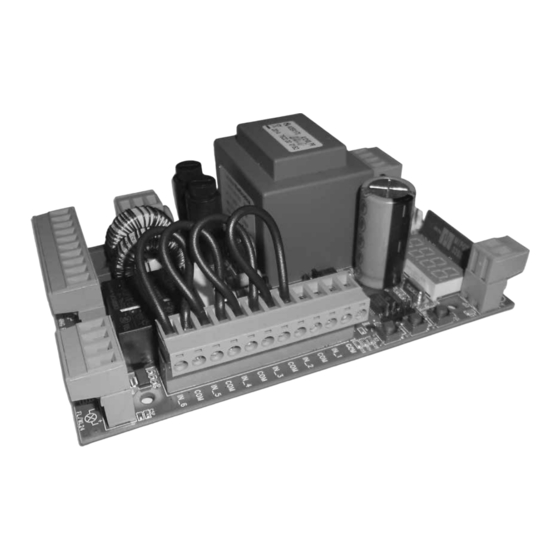
2 PRODUCT DESCRIPTION NET230N is a universal control panel for DEA System 1 or 2 230V operators automations with or without encoder. The main feature of this control board is its ease of configuration of inputs and outputs according to any needs thus ensuring adapta- bility to any type of automation. -
Page 6: Configurations
4 CONFIGURATION OF THE CONTROL PANEL The universal control unit NET230N can be used for the management of the following types ( ) of closures motorized by DEA Sy- stem: swing and sliding gates, overhead doors and barriers. In order to ensure maximum adaptability to each... -
Page 7: Electrical Connections
5 ELECTRICAL CONNECTIONS Execute the wiring following the directions of table 1 and diagrams. WARNING For adequate electrical safety, keep low safety voltage wires (controls, electro-locks, antenna, auxiliary power) clearly separate from 230V ~ power wires (minimum 4 mm in air or 1 mm via supplementary insulation) placing them in plastic raceways and securing them with adequate clamps near terminal boards. - Page 8 Basic scheme NET230N DISPLAY DISPLAY ENC_M1 ENC_M2 34 33 32 31 30 29 Serial N° 000X XXXXXX CON 1 NET-EXP IN_1 CON 2 NET-NODE / MEMONET IN_2 IN_3 IN_4 IN_5 IN_6 11 12 WARNING FLASH LOCK WL/FL MOT 1 MOT 2...
- Page 9 OPEN GATE WARNING LIGHT 230V max 150W N.O. N.C. BLACK OMNIPOLAR CIRCUIT BRAKER GRAY POWER SUPPLY BROWN 230V~ 50Hz ±10% 3 x 1,5 mm...
- Page 10 N.O. N.C. OPEN GATE WARNING LIGHT 230V max 150W ELECTRIC-LOCK art.110 N.O. N.C. BLACK GRAY BROWN BROWN GRAY OMNIPOLAR CIRCUIT BRAKER BLACK POWER SUPPLY 230V~ 50Hz ±10% 3 x 1,5 mm WHITE WHITE GREEN GREEN BROWN BROWN...
- Page 11 N.O. N.C. BROWN GRAY BLACK BROWN GRAY OMNIPOLAR CIRCUIT BRAKER BLACK POWER SUPPLY 230V~ 50Hz ±10% 3 x 1,5 mm BROWN BROWN GRAY GRAY BLACK BLACK BROWN BROWN GREEN GREEN WHITE WHITE COURTESY LIGHT COURTESY LIGHT 230V 230V...
- Page 12 OPEN GATE WARNING LIGHT 230V max 150W ELECTRO-MAGNET N.O. N.C. BROWN OMNIPOLAR CIRCUIT BRAKER GRAY POWER SUPPLY BLACK 230V~ 50Hz ±10% 3 x 1,5 mm...
- Page 13 N.O. N.C. BLACK OMNIPOLAR CIRCUIT BRAKER GRAY POWER SUPPLY BROWN 230V~ 50Hz ±10% 3 x 1,5 mm OPEN GATE WARNING LIGHT 230V max 150W...
-
Page 14: Standard Programming
6 STANDARD PROGRAMMING WARNING For reversible motors with electromagnetic brake, remember to set P062=3. 1 Power Supply When turned on, “ ”, “ ” (or the current firmware version) “ ”, “ ” (or the selected Type) appear on the display in sequence followed by the closed gate symbol “- - - - ”. - Page 15 Warning: If you are using non DEA System operators, set the parameter on the closer value for family type and performances (refer to table on page 35).
- Page 16 7 How to adjust the limit switche 1. Scroll down the parameters untill you visualize P001; 2. confirm by pressing the key; 3. by pressing (OPEN) and (CLOSE), move the leaf in the opening position and adjust the limit switch cam so that it pushes the microswitch in that point;...
- Page 17 9.2 Learning 1. Scroll down the parameters with keys until you visualise P005; 2. Confirm by pressing on the key; 3. When the symbol “ ” appears, press on any key of the transmitter you want to memo- rize; 4. The display visualizes the number of the trans- mitter just memorized and then “...
-
Page 18: Advanced Programming
7 ADVANCED PROGRAMMING Here are some added programming procedures relating to remotes memory management and advanced configuration of the control inputs. 1 Deletion of memorized transmitters 1.1 Deletion of all transmitters 1. Scroll down the parameters until you visualize P004; 2. - Page 19 3 Locking-Unlocking access to programming By using a “dip-switch” remote (regardless of the type of remotes already memorized) it’s possible to lock-unlock access to the program- ming of the control panel to avoid tampering. The remote setting is the locking-unlocking code verified by the control board. 3.1 Locking access to programming 1.
- Page 20 4 Downloading/uploading data memory 4.1 Downloading data to an external memory unit (DOWNLOAD) 1. Scroll down the parameters with keys until you visualize P011; 2. Press the key, the display visualizes the word “ ” flashing; 3. Press the again and continue pressing it for 5 sec (if you release it before this period, the procedure is stopped); 4.
-
Page 21: Messages Shown On The Display
8 MESSAGES SHOWN ON THE DISPLAY WORKING STATUS MESSAGES Mess. Description Gate is closed Gate is opened Opening under way Closing under way While in step-by-step mode, the control board awaits further instructions after a start command Stop input intervened or an obstacle is detected with limited inversion duration (P055 > 0 or P056 > 0) Board in BOOT-MODE: Indicates that the firmware is corrupted or updating. -
Page 22: Installation Test
9 INSTALLATION TEST The testing operation is essential in order to verify the correct installation of the system. DEA System wants to summarize the proper testing of all the automation in 4 easy steps: ● Make sure that you comply strictly as described in paragraph 2 “WARNINGS SUMMARY”;... - Page 24 PAR. PROCEDURE Positioning of operator 1 Positioning of operator 2 Memorization of the motors’ stroke Deletion of transmitters Transmitters memorizing Search and deletion of a transmitter Restoring the operating parameters Lock access to programming How to learn connected DE@NET devices (unused at the moment) Restoring the “I/O”...
- Page 25 SETTABLE VALUES DEFAULT VALUES (for different standards of installation) SETTABLE VALUES TYPE TYPE TYPE TYPE TYPE • 000: IN3 type=free contact • 001: IN3 type=constant resistance 8K2 • 000: NONE (unused parameter) • 001: START (start) • 002: PED. (pedestrian) •...
- Page 26 Allocation of CHANNEL 1 of remotes Allocation of CHANNEL 2 of remotes Allocation of CHANNEL 3 of remotes Allocation of CHANNEL 4 of remotes Selection of type of remotes Selection type of operators Warning: Selecting the OLI operators, all indicated values related to the operator force (P037 - P038 - P039 - P040), are automatically set to 100% without any possibility of change.
- Page 27 TYPE TYPE TYPE TYPE TYPE • 000: NONE (unused) • 001: START (start) • 002: PEDESTRIAN (pedestrian) • 003: OPEN (separated open) • 004: CLOSED (separated close) • 005: Unused • 006: Unused • 007: ELOCK-IN (electric-lock activation. See P062) •...
- Page 28 Pedestrian automatic closing time adjustment (se = 0 pedestrian automatic closing deactivated) Pedestrian stroke duration adjustment Pre-flashing time adjustment Adjustment of phase displacement time while opening Adjustment of phase displacement time while closing Collectivity function: if it is activated it deactivates both opening and closing inputs for the whole duration of automatic opening and closing Ram blow function: if=0 “Ram blow”...
- Page 29 TYPE TYPE TYPE TYPE TYPE 0sec........255sec 5%tot…......100%tot 0sec…….10sec 0sec……………30sec 0sec……………30sec • 000: disabled • 001: activated only upon opening • 002: activated on automatic opening and closing • 000: “ram blow” deactivated • 001: “ram blow function” activated • >001: “ram blow” periodic (X*1 min) (2........255) •...
- Page 30 TYPE 00 - 01 - 03 ONLY: Adjustment of the opening stroke margin: it adjusts the duration of the last part of the stroke during which an obstacle is interpreted as a stroke, blocking the motor without performing the inversion. For motors with encoders, the set value indicates the number of revolutions of the rotor;...
- Page 31 TYPE TYPE TYPE TYPE TYPE 1....255 (motors with encoder) 1%…....100% (motors without encoder) 0........255 1....255 (motors with encoder) 1%…....100% (motors without encoder) 1........255 0%tot…......100%tot 0%tot…......100%tot • 000: “Boost” output for electric-lock art.110 power supply • 001: “24V pulse output max 5W •...
- Page 32 Operation of the SFT input: if = 0 safety edge always enabled, if = 1 safety edge enabled only SAFETY 1 while closing, if = 2 safety edge enabled only while closing and before any movement, if = 3 safety edge enabled only when opening, if = 4 safety edge enabled only while opening and before any movement;...
- Page 33 TYPE TYPE TYPE TYPE TYPE • 000: “safety edge always enabled • 001: “safety edge enabled only while closing • 002: “safety edge enabled only while closing and before any movement • 003: “safety edge enabled only when opening • 004: “safety edge enabled only while opening and before any movement •...
- Page 35 Eseguire il fissaggio alla parete usando opportuni tasselli per viti Ø5 (non fornite); Fix the box on the wall with appro- priate bushings to anchor screws Ø5 (not included); Le fixer au mur en utilisant des douilles à expansion pour vis adéqua- tes Ø5 (pas incluses);...
- Page 36 VISTA DA “A” Fori da eseguire sul fondo della scatola con seghe a tazza Ø37 per l’inserimento dei fermatubi; VIEW FROM “A” Holes to be drilled on the bottom of the box with a hole saw Ø37 to introduce tube fastening; VUE DE “A” Trous à per- cer au fond du boîtier avec une scie-cloche Ø37 afin d’introduire des bloque tube;...
- Page 37 NET230N/C 34 33 32 31 30 29 MOT 1 MOT 2 11 12...
- Page 39 E-Mail address: deasystem@deasystem.com declare that the DoC is issued under our sole responsibility and belongs to the following product: Apparatus model/Product: NET230N - NET230N/C Type: Universal control panel for 230V operators Batch: See the label on the back of the user manual...
- Page 40 BATCH DEA SYSTEM S.p.A. Via Della Tecnica, 6 - 36013 PIOVENE ROCCHETTE (VI) - ITALY tel: +39 0445 550789 - fax: +39 0445 550265 Internet: http:\\www.deasystem.com - E-mail: deasystem@deasystem.com...
Need help?
Do you have a question about the NET230N and is the answer not in the manual?
Questions and answers