Table of Contents
Advertisement
Quick Links
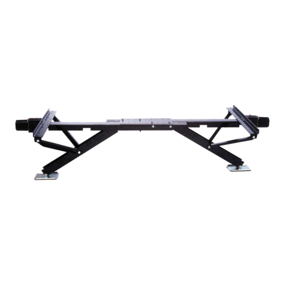
APPLICATION
The primary purpose of your Power Twin II is to provide
rock solid stabilization for maximum comfort while
using your RV in a parked position. To obtain this
desired end result and eliminate the possibility of
damage to your RV or the Power Twin II, it is very
important to follow these step‐by‐step instructions.
IMPORTANT: DO NOT OPERATE THE POWER TWIN II
BEFORE READING THE OPERATING INSTRUCTIONS.
The Power Twin II will assist you in final lifting and
leveling, based on the Power Twin II Power Curve Graph
which shows pounds of lift in relation to the ground
clearance from the bottom of the frame.
By measuring the ground clearance on your RV you can
determine the maximum amount of lift your Power
Twin II will provide for final leveling.
NOTE: THE POUNDS OF LIFT INCREASES AS THE
DISTANCE, FROM GROUND TO FRAME, INCREASES.
SAFETY AND DAMAGE WARNING
CAUTION: ALWAYS FOLLOW THESE
INSTALLATION AND OPERATING
INSTRUCTIONS TO PREVENT DAMAGE TO
YOUR RV AND TO PREVENT PERSONAL
INJURY.
ULTRA POWER TWIN II-30
ULTRA POWER TWIN II-22
INSTALLATION/OPERATION
INSTALLATION
The Power Twin II‐30 does not come assembled.
Please follow all of the steps of these instructions. The
Power Twin II‐22 is pre‐assembled, so please skip to
Step 3.
❶ Attach mounting plate (#2) to main assembly
channel (#1) using four (4) M8‐1.25x25mm carriage
bolts (#14) and four (4) M8x1.25 NYLOCK nuts
(#15). Make sure the mounting plate is square to
the main channel assembly before tightening the
nuts.
❷ Attach the two (2) arm support braces (#13)
to the mounting plate (#2) using two (2)
M12‐1.75x30mm hex head bolts (#16) and two (2)
M12x1.75 NYLOCK nuts (#17).
Place the plastic washer (#11) between the arm
and the mounting bracket. Attach the other end
of the arm support braces to the leg assembly (#8)
using one (1) M12‐1.75x100mm hex head bolt (#18)
and one (1) M12x1.75 NYLOCK nut (#17) by placing
the leg spacer (#10) inside the leg assembly and
pushing the bolt through the one side of the leg,
through the spacer and out of the other side of the
leg channel.
Be sure to place the plastic washer (#11) between
the arm and the leg brace before pushing the bolt
through the hole.
Tighten all bolts and nuts until snug. Do not over
tighten as these are pivot points.
REPEAT steps 1 and 2 for the second leg assembly
(39‐841700 PTII‐30).
P/N 39-941705
P/N 39-941707
REV 12/2013
Advertisement
Table of Contents

Related Manuals for Ultra-Fab ULTRA POWER TWIN II-30


Summary of Contents for Ultra-Fab ULTRA POWER TWIN II-30
- Page 1 ULTRA POWER TWIN II-30 P/N 39-941705 ULTRA POWER TWIN II-22 P/N 39-941707 REV 12/2013 INSTALLATION/OPERATION APPLICATION INSTALLATION The primary purpose of your Power Twin II is to provide The Power Twin II‐30 does not come assembled. rock solid stabilization for maximum comfort while Please follow all of the steps of these instructions. The using your RV in a parked position. To obtain this ...
- Page 2 ULTRA POWER TWIN II-30 P/N 39-941705 ULTRA POWER TWIN II-22 P/N 39-941707 REV 12/2013 ❸ Measure the outside width of the main frame MOTOR INSTALLATION channel of your RV. Lay out the two (2) Power Twin leg assemblies (see figure in this section ❶ Attach each of the motor and gear box ...
- Page 3 ULTRA POWER TWIN II-30 P/N 39-941705 ULTRA POWER TWIN II-22 P/N 39-941707 REV 12/2013 ❼ Replace the fuse (#28) and test the Power INSTRUCTIONS FOR USE Twin II, one leg at a time. Check to see that the switches are wired in a logical relationship (UP ...
- Page 4 ULTRA POWER TWIN II-30 P/N 39-941705 ULTRA POWER TWIN II-22 P/N 39-941707 REV 12/2013 ...
- Page 5 ULTRA POWER TWIN II-30 P/N 39-941705 ULTRA POWER TWIN II-22 P/N 39-941707 REV 12/2013 ‐ ‐ DELUXE 5 WHEEL LANDING GEAR, ULTRA SWAY CONTROL, WEIGHT DISTRIBUTION HITCH, BALL MOUNTS, HITCH BALLS, ODYSSEY 3000/4000 TONGUE JACKS, POWERTWIN II STABILIZERS, THE ELIMINATOR STABILIZER, LEVELING BLOCKS AND MANUAL TONGUE JACKS THE MANUFACTURER NAMED BELOW MAKES THE FOLLOWING WARRANTY WITH RESPECT TO THE ABOVE ULTRA‐FAB PRODUCTS This Warranty is made only to the first Purchaser (hereinafter called the “Original Purchaser”) who acquires this product for their own use. This Warranty will be in effect for three years from the date of purchase by the Original Purchaser. It is suggested that the Original ...
Need help?
Do you have a question about the ULTRA POWER TWIN II-30 and is the answer not in the manual?
Questions and answers