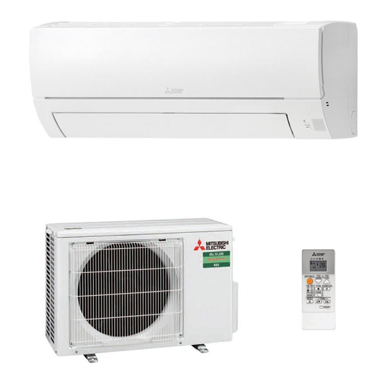
Mitsubishi Electric MSZ-HR25VF-E1 Service Manual
Indoor unit
Hide thumbs
Also See for MSZ-HR25VF-E1:
- Service manual (65 pages) ,
- Service manual (65 pages) ,
- Service manual (60 pages)
Table of Contents
Advertisement
SERVICE MANUAL
Models
MSZ-HR25VF
MSZ-HR35VF
MSZ-HR42VF
MSZ-HR50VF
MSZ-HR25VF
-
E1
ER1
ET1
,
,
-
E1
ER1
ET1
,
,
-
E1
ER1
ET1
,
,
-
E1
ER1
ET1
,
,
CONTENTS
1. TECHNICAL CHANGES ∙∙∙∙∙∙∙∙∙∙∙∙∙∙∙∙∙∙∙∙∙∙∙∙∙∙∙∙∙∙∙∙∙∙∙ 2
2. PART NAMES AND FUNCTIONS ∙∙∙∙∙∙∙∙∙∙∙∙∙∙∙∙∙∙∙∙∙ 3
3. SPECIFICATION ∙∙∙∙∙∙∙∙∙∙∙∙∙∙∙∙∙∙∙∙∙∙∙∙∙∙∙∙∙∙∙∙∙∙∙∙∙∙∙∙∙∙∙∙∙∙∙∙ 4
4. NOISE CRITERIA CURVES ∙∙∙∙∙∙∙∙∙∙∙∙∙∙∙∙∙∙∙∙∙∙∙∙∙∙∙∙∙∙ 5
5. OUTLINES AND DIMENSIONS ∙∙∙∙∙∙∙∙∙∙∙∙∙∙∙∙∙∙∙∙∙∙∙∙ 6
6. WIRING DIAGRAM ∙∙∙∙∙∙∙∙∙∙∙∙∙∙∙∙∙∙∙∙∙∙∙∙∙∙∙∙∙∙∙∙∙∙∙∙∙∙∙∙∙∙∙∙ 7
7. REFRIGERANT SYSTEM DIAGRAM ∙∙∙∙∙∙∙∙∙∙∙∙∙∙∙ 8
8. SERVICE FUNCTIONS ∙∙∙∙∙∙∙∙∙∙∙∙∙∙∙∙∙∙∙∙∙∙∙∙∙∙∙∙∙∙∙∙∙∙∙ 10
9. MICROPROCESSOR CONTROL ∙∙∙∙∙∙∙∙∙∙∙∙∙∙∙∙∙∙∙ 12
10. TROUBLESHOOTING ∙∙∙∙∙∙∙∙∙∙∙∙∙∙∙∙∙∙∙∙∙∙∙∙∙∙∙∙∙∙∙∙∙∙∙∙∙ 16
11. DISASSEMBLY INSTRUCTIONS ∙∙∙∙∙∙∙∙∙∙∙∙∙∙∙∙∙∙∙∙ 29
PARTS CATALOG (OBB822)
No. OBH822
Outdoor unit service manual
MUZ-HR∙VF Series (OBH823)
Advertisement
Table of Contents

Related Manuals for Mitsubishi Electric MSZ-HR25VF-E1


Summary of Contents for Mitsubishi Electric MSZ-HR25VF-E1
-
Page 1: Table Of Contents
INDOOR UNIT No. OBH822 SERVICE MANUAL Models MSZ-HR25VF MSZ-HR35VF MSZ-HR42VF MSZ-HR50VF Outdoor unit service manual MUZ-HR∙VF Series (OBH823) CONTENTS 1. TECHNICAL CHANGES ∙∙∙∙∙∙∙∙∙∙∙∙∙∙∙∙∙∙∙∙∙∙∙∙∙∙∙∙∙∙∙∙∙∙∙ 2 2. PART NAMES AND FUNCTIONS ∙∙∙∙∙∙∙∙∙∙∙∙∙∙∙∙∙∙∙∙∙ 3 3. SPECIFICATION ∙∙∙∙∙∙∙∙∙∙∙∙∙∙∙∙∙∙∙∙∙∙∙∙∙∙∙∙∙∙∙∙∙∙∙∙∙∙∙∙∙∙∙∙∙∙∙∙ 4 4. NOISE CRITERIA CURVES ∙∙∙∙∙∙∙∙∙∙∙∙∙∙∙∙∙∙∙∙∙∙∙∙∙∙∙∙∙∙ 5 5. -
Page 2: Technical Changes
Use the specified refrigerant only Never use any refrigerant other than that specified. Doing so may cause a burst, an explosion, or fire when the unit is being used, serviced, or disposed of. Correct refrigerant is specified in the manuals and on the spec labels provided with our products. We will not be held responsible for mechanical failure, system malfunction, unit breakdown or accidents caused by failure to follow the instructions. -
Page 3: Part Names And Functions
PART NAMES AND FUNCTIONS MSZ-HR25VF MSZ-HR35VF MSZ-HR42VF MSZ-HR50VF Heat exchanger Front panel Air inlet Air filter Air cleaning filter (Silver-ionized air purifier filter, option) Horizontal vane Air outlet Operation indicator lamp Remote control receiving section Emergency operation switch Remote controller ACCESSORIES MSZ-HR25VF MSZ-HR35VF... -
Page 4: Specification
SPECIFICATION Indoor model MSZ-HR25VF MSZ-HR35VF MSZ-HR42VF MSZ-HR50VF Power supply Single phase 230 V, 50 Hz Cooling Power input Heating Cooling 0.20 0.27 0.30 0.36 Running current Heating 0.20 0.27 0.30 0.36 Model RC0J30-CV Cooling 0.20 0.27 0.30 0.36 Current Heating 0.20 0.27 0.30... -
Page 5: Noise Criteria Curves
NOISE CRITERIA CURVES MSZ-HR25VF MSZ-HR35VF FUNCTION SPL(dB(A)) LINE FUNCTION SPL(dB(A)) LINE COOLING COOLING HEATING HEATING NC-70 NC-70 NC-60 NC-60 NC-50 NC-50 NC-40 NC-40 NC-30 NC-30 NC-20 NC-20 1000 2000 4000 8000 1000 2000 4000 8000 BAND CENTER FREQUENCIES, Hz BAND CENTER FREQUENCIES, Hz MSZ-HR42VF MSZ-HR50VF FUNCTION SPL(dB(A)) -
Page 6: Outlines And Dimensions
OUTLINES AND DIMENSIONS MSZ-HR25VF MSZ-HR35VF MSZ-HR42VF MSZ-HR50VF Unit: mm OBH822... -
Page 7: Wiring Diagram
WIRING DIAGRAM MSZ-HR25VF MSZ-HR35VF MSZ-HR42VF MSZ-HR50VF OBH822... -
Page 8: Refrigerant System Diagram
REFRIGERANT SYSTEM DIAGRAM MSZ-HR25VF Unit: mm Refrigerant pipe ø9.52 (with heat insulator) Indoor coil Indoor thermistor heat RT12 exchanger Flared connection Indoor coil thermistor RT13 Room temperature thermistor RT11 Flared connection Refrigerant pipe ø6.35 (with heat insulator) Refrigerant flow in cooling MSZ-HR35VF Refrigerant pipe ø9.52 (with heat insulator) - Page 9 MSZ-HR42VF MSZ-HR50VF Unit: mm Refrigerant pipe ø9.52 (with heat insulator) Indoor coil Indoor thermistor heat RT12 exchanger Flared connection Indoor coil thermistor RT13 Room temperature thermistor RT11 Flared connection Refrigerant pipe ø6.35 (with heat insulator) Refrigerant flow in cooling OBH822...
-
Page 10: Service Functions
SERVICE FUNCTIONS MSZ-HR25VF MSZ-HR35VF MSZ-HR42VF MSZ-HR50VF 8-1. TIMER SHORT MODE For service, the following set time can be shortened by bridging the timer short mode point on the electronic control P.C. board. (Refer to 10-7.) • The set time for the ON/OFF timer can be reduced to 1 second for each minute. •... -
Page 11: Indoor Unit
8-3. AUTO RESTART FUNCTION When the indoor unit is controlled with the remote controller, the operation mode, the set temperature, and the fan speed are memorized by the indoor electronic control P.C. board. “AUTO RESTART FUNCTION” automatically starts operation in the same mode just before the shutoff of the main power. -
Page 12: Microprocessor Control
MICROPROCESSOR CONTROL MSZ-HR25VF MSZ-HR35VF MSZ-HR42VF MSZ-HR50VF WIRELESS REMOTE CONTROLLER Signal transmitting section Operation display section STOP/OPERATE (OFF/ON) button Fan speed control button Temperature buttons ECONO COOL button Operation select button Vane control button Timer mode select button Time set buttons RESET button NOTE: Last setting will be stored after the unit is turned OFF with the remote controller. -
Page 13: Indoor Unit
9-1. COOL ( ) OPERATION (1) Press STOP/OPERATE (OFF/ON) button. OPERATION INDICATOR lamp of the indoor unit turns on with a beep tone. (2) Select COOL mode with OPERATION SELECT button. (3) Press TEMPERATURE buttons (TOO WARM or TOO COOL button) to select the desired temperature. The setting range is 16 - 31°C. -
Page 14: Cooling
9-5. MULTI SYSTEM OPERATION FOR MULTI SYSTEM AIR CONDITIONER OUTDOOR UNIT: MXZ series Multi system air conditioner can connect 2 or more indoor units with 1 outdoor unit. • When you try to operate 2 or more indoor units with 1 outdoor unit simultaneously, one for the cooling and the oth- ers for heating, the operation mode of the indoor unit that operates first is selected. -
Page 15: Indoor Unit
9-7. TIMER OPERATION (ON/OFF TIMER) 1. How to set the timer (1) Press STOP/OPERATE/ (OFF/ON) button to start the air conditioner. (2) Select the timer mode by pressing the button during operation. Each time this button is pressed, the timer mode is changed in sequence: (OFF TIMER) →... -
Page 16: Troubleshooting
TROUBLESHOOTING MSZ-HR25VF MSZ-HR35VF MSZ-HR42VF MSZ-HR50VF 10-1. CAUTIONS ON TROUBLESHOOTING 1. Before troubleshooting, check the following 1) Check the power supply voltage. 2) Check the indoor/outdoor connecting wire for miswiring. 2. Take care of the following during servicing 1) Before servicing the air conditioner, be sure to turn OFF the main unit first with the remote controller, and after confirm- ing the horizontal vane is closed, turn OFF the breaker and/or disconnect the power plug. -
Page 17: Indoor Unit
10-2. FAILURE MODE RECALL FUNCTION Outline of the function This air conditioner can memorize the abnormal condition which has occurred once. Even though LED indication listed on the troubleshooting check table (10-4.) disappears, the memorized failure details can be recalled. 1. -
Page 18: Indoor Unit
2. Table of indoor unit failure mode recall function Left lamp of OPERA- Abnormal point TION INDICATOR Condition Remedy (Failure mode) lamp Not lit Normal — — The room temperature thermistor short or 1-time blink every Room tempera- Refer to the characteristics of the room temperature open circuit is detected every 8 seconds dur- 0.5-second ture thermistor... -
Page 19: Indoor Unit
10-3. INSTRUCTION OF TROUBLESHOOTING Start Indoor unit operates. Indoor unit oper- Indoor unit does OPERATION INDICATOR Outdoor unit does not receive the ates. lamp on indoor unit is not operate normally. signal from re- Outdoor unit blinking ON and OFF. does not operate. -
Page 20: Indoor Unit
10-4. TROUBLESHOOTING CHECK TABLE Before taking measures, make sure that the symptom reappears for accurate troubleshooting. When the indoor unit has started operation and detected an abnormality of the following condition (the first detection after the power ON), the indoor fan motor turns OFF and OPERATION INDICATOR lamp blinks. OPERATION INDICATOR Blinking Not lit... -
Page 21: Indoor Unit
OPERATION INDICATOR Blinking Not lit Abnormal Operation indicator lamp Symptom Condition Remedy point Left lamp lights and right lamp blinks. The operation mode of the each indoor unit is MXZ type Outdoor unit differently set to COOL (includes DRY, FAN) •... - Page 22 10-6. TROUBLESHOOTING FLOW A Check of indoor fan motor The indoor fan motor error has occurred, and the indoor fan does not operate. Turn OFF the power supply. Pay enough attention to the high voltage on the fan motor connector CN211. Turn ON the power supply, wait 5 seconds or more, and then press EMERGENCY OPERATION switch.
- Page 23 B Check of remote controller and indoor electronic control P.C. board Check if the remote controller is exclusive for this air conditioner. Press STOP/OPERATE (OFF/ON) button on the remote controller. Is LCD display on the remote controller Replace the batteries. (Refer to 10-1.4.) visible? (Not clear) Remove the batteries, then set them back...
- Page 24 C Check of indoor P.C. board and indoor fan motor Turn OFF the power supply. Remove indoor fan motor connector CN211 Measure the resistance of indoor fan Short circuit: and vane motor connector CN151 from the motor. Replace the indoor fan motor. indoor electronic control P.C.
-
Page 25: Indoor Unit
D How to check miswiring and serial signal error NOTE: Refer to the outdoor unit service manual. MUY Type Turn OFF the power supply. Is there rated voltage in the power supply? Check the power supply. Turn ON the power supply. Is there rated voltage between outdoor terminal block S1 and S2? Check the wiring. -
Page 26: Indoor Unit
MXZ Type Turn OFF the power supply. LED indication for communication status Communication status is indicated Is there rated voltage in by the LED. Check the power the power supply? supply. Unit status Blinking: normal communication Lighting: abnormal communication or not connected Turn ON the power supply. -
Page 27: Indoor Unit
E Electromagnetic noise enters into TV sets or radios Is the unit earthed? Earth the unit. Is the distance between the antennas Extend the distance between the antennas and and the indoor unit within 3 m, or is the the indoor unit, and/or the antennas and the distance between the antennas and the outdoor unit. - Page 28 10-7. TEST POINT DIAGRAM AND VOLTAGE 1. Indoor electronic control P.C. board, indoor terminal P.C. board and power monitor receiver SW P.C. board MSZ-HR25VF MSZ-HR35VF MSZ-HR42VF MSZ-HR50VF Indoor electronic control P.C. board Connector to Indoor coil thermistor (CN112) RT12, RT13 Connector to Indoor Indoor terminal P.C.
-
Page 29: Disassembly Instructions
DISASSEMBLY INSTRUCTIONS <Detaching method of the terminal with locking mechanism> The terminal which has the locking mechanism can be detached as shown below. There are following 2 types of the terminal with locking mechanism. The terminal without locking mechanism can be detached by pulling it out. Check the shape of the terminal before detaching. - Page 30 OPERATING PROCEDURE PHOTOS/FIGURES 2. Removing the indoor terminal P.C. board, indoor Photo 2 electronic control P.C. board, and power monitor Water cover Earth plate Coil thermistor receiver SW P.C. board and the electrical box <Removing the electrical box> (1) Remove the panel. (Refer to section 1.) Screw of the Remove the right corner box.
- Page 31 OPERATING PROCEDURE PHOTOS/FIGURES 3. Removing the nozzle assembly and the vane Photo 5 motor <Removing the nozzle assembly> (1) Remove the panel (Refer to section 1.) and the corner box. (2) Remove the V.A. clamp, and then the indoor/outdoor connecting wire. (Refer to section 2.) (3) Remove the electrical cover.
- Page 32 OPERATING PROCEDURE PHOTOS/FIGURES 4. Removing the indoor fan motor, the indoor coil Photo 7 thermistor and the line flow fan (1) Remove the panel. (Refer to section 1.) Remove the corner box. (2) Remove the electrical box and the nozzle assembly. (Refer to section 2,3.) (3) Remove the screws fixing the motor bed.
- Page 33 Fixing the indoor coil thermistor There are 2 forms of parts for fixing the indoor coil thermistor. When fixing the indoor coil thermistor to the clip-shape/holder-shape part, the Clip shape Holder shape lead wire should point down. About the same length Position and procedure for mounting the clip-shape part 1.
- Page 34 HEAD OFFICE: TOKYO BUILDING, 2-7-3, MARUNOUCHI, CHIYODA-KU, TOKYO 100-8310, JAPAN © Copyright 2018 MITSUBISHI ELECTRIC CORPORATION Published: Oct. 2018. No. OBH822 Made in Japan Specifications are subject to change without notice.
Need help?
Do you have a question about the MSZ-HR25VF-E1 and is the answer not in the manual?
Questions and answers