Page 1
INSTALLATION AND 
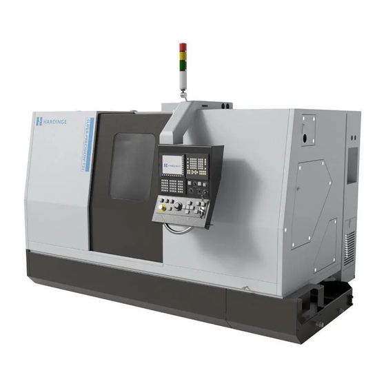
EXTENDED STORAGE INSTRUCTIONS TI7878A T-42 T-51 T-65 Multi-Tasking CNC Lathes ATTENTION READ THE ENCLOSED INFORMATION BEFORE REMOVING THE MACHINE FROM THE SKID. Revised: July 25, 2012 Original Instructions Manual No. M-507C Litho in U.S.A. Part No. M C-0009500-0507...
Page 2
This manual covers the installation and extended storage of Hardinge T-42, T-51, and T-65 Multi-Tasking CNC lathes. In no event will Hardinge Inc. be responsible for indirect or consequential damage resulting from the use or application of the information in this man- ual.
MACHINE DESCRIPTION AND INTENDED USE Applicable Machines: T-42, T-51, and T-65 Lathes These lathes are numerically controlled machine tools designed to shape cold metal by the appli- cation of a cutting tool and rotating workpiece capable of performing two or more machining pro- cesses (e.g.
DO NOT climb into the machine guard! You may become entrapped. Due to the compact size of the Hardinge lathes and the provision of side access doors to allow servicing of the machine, it is not necessary to climb into the machine guard.
CHAPTER 1 - INSTALLATION MACHINE INSTALLATION REQUIREMENTS T-42, T-51, and T-65 lathes require a substantial foundation. Do not locate the machine near equip- ment that causes vibration. Poor surface finishes or damage to the control may result from vibration transmitted to the machine.
MACHINE DIMENSIONS T-42 AND T-42 BIG-BORE LATHES Minimum Recommended Space to Allow 24.0 Power Case Platform to be Moved to Perform [610] Service at the Back of the Machine. Provide Clearance for 29.4 Power Case Door Swing [747] Main Power Entrance 101.4 [2576] Main Air Connection...
T-51 AND T-65 LATHES - NOTE - Refer to Figure 1.2 for T-51 and T-65 lathes with serial numbers DQ-101 through DQ-110, DQ-112, DQ-117, and DQ-120. Refer to Figure 1.3 for T-51 and T-65 lathes with serial numbers DQ-111, DQ113 through DQ-116, DQ-118, DQ-119, DQ-121 and later.
Page 12
[2370] 128.2 43.2 [3257] [1097] Optional Chip Conveyor Note: Dimensions are Inches [Millimeters] TI5886 Figure 1.3 - Machine Dimensions and Support Feet Locations: T-51 and T-65 Lathes (Machine Serial Numbers DQ-111, DQ113 through DQ-116, DQ-118, DQ-119, DQ-121 and Later) M-507C...
SETTING THE MACHINE - NOTE - Review the machine installation requirements on page 1-1 before beginning the installation. 1. Verify that the foundation for the machine meets the requirements, as outlined on page 1-1. 2. Leave the machine on the skid and move it to the installation location. 3.
3. Drill 3/4 inch [19 millimeter] diameter holes, 4 inches [102 millimeters] deep. 4. Remove any debris from the drilled holes. Left End of Machine Right End of Machine Hold-Down Brackets TI5849 Figure 1.4 - Machine Hold-Down Brackets (T-51 Machine Shown) M-507C...
Page 15
5. Drive an expansion shield down to the bottom of each hole. Refer to Figure 1.5. 6. Attach the brackets to the machine base using the M12 screws, washers, and lock washers retained during the previous procedure. 7. Secure the brackets to the floor using the lag screws and flat washers provided. Lag Screw Flat Washer Hold-Down Bracket...
DO NOT discard the shipping brackets or mounting hardware. The brackets must be installed whenever the machine is to be moved. T-51 and T-65 lathes shipped in containers have the control pendant mounted at the right end of the machine during shipment. Information on mounting the control pendant in operating position begins on page 1-15.
3. Remove the screws to release the bracket from the pendant. 4. Install all screws back in location to seal the holes. REMOVING THE GUARD DOOR SHIPPING BRACKET (T-51 AND T-65 LATHES) Remove guard door shipping bracket "B", Figure 1.7.
REMOVING THE GUARD SUPPORT BRACKETS (T-51 AND T-65 LATHES) Remove the left and right guard support brackets, shown in Figure 1.8. Left Guard Right Guard Support Bracket Support Bracket Isometric View of Brackets TI5852 Figure 1.8 - Guard Support Brackets...
1.10, from the platform. 3. Release the upper end of bracket "D" and remove. 4. On T-51 and T-65 lathes: A) Remove the nut and washer under the tray to release the lower end of bracket “E”, Figure 1.11, from the machine.
INSTALLING THE INTERLOCK SWITCH ON THE REAR ACCESS DOOR For shipping purposes, the rear access door interlock switch is stowed next to the hydraulic unit heat exchanger. Refer to Figure 1.13. 1. Using the fasteners supplied with the switch, mount the interlock switch on the access door, as shown in Figure 1.14.
POWER CASE PLATFORM - NOTE - The power case platform is equipped with two threaded platform legs. 1. Rotate two threaded platform legs “G”, Figure 1.15, downward until contact is made with the floor. 2. Rotate the platform legs an additional ¼ turn. 3.
Page 22
Shipping Tubes Shipping Tubes TP7940 TP7941 Figure 1.17 - Shipping Tubes Figure 1.18 - Shipping Tubes Attached to Machine Pedestal Under Power Case Platform (Components Removed for Clarity) 5. Remove the retaining screws from the three shipping tubes, shown in Figure 1.17. - NOTE - The shipping tubes are equipped with M8 threaded holes.
MOUNTING THE CONTROL PENDANT IN OPERATING POSITION - NOTE - T-51 and T-65 lathes shipped in containers have the control pendant mounted at the right end of the machine during shipment. Door lock “J”, Figure 1.19, is located on the top of the machine.
Page 24
3. Replace the cap screw on the door lock. 4. Remove access cover “M”, Figure 1.22. 5. At the right end of the machine, attach a hoist with lifting strap to the eyebolt on lifting bracket “N”, Figure 1.23. 6. Apply tension to the lifting strap to support the pendant and wireway when the fasteners are removed.
Page 25
Lower Front Attachment Points Upper Front Attachment Points TP8353 TP8349 Figure 1.26 - Lower Front Attachment Point Figure 1.27 - Upper Front Attachment Point 9. Remove the eight screws that secure the wireway to the machine. 10. Carefully lift the pendant and wireway. 11.
CLEANING THE MACHINE - CAUTION - Do not use compressed air to clean the machine. Air pressure forces dirt and other foreign matter past the seals and covers into the slides, ball screws, and bearings. This causes additional wear and will reduce the life and accuracy of the machine.
SETTING THE MACHINE AIR PRESSURE - NOTE - Do not turn the air supply ON. The Hardinge technician will check the in- coming air line connection. Once the air line connection has been checked: 1. Turn main air valve "V", Figure 1.30, ON.
SPINDLE CHILLER INSTALLATION The spindle chiller is a stand-alone unit that reduces and stabilizes the temperature of the spin- dle(s). Refer to the chiller installation and maintenance manual for additional information. Keep the chiller unit documentation with the machine maintenance manual (M-506). The following items are to be connected to the chiller unit: Inlet and Outlet hoses (labeled for connection) •...
Page 29
TP7873A TP7874A Figure 1.34 -Chiller Unit Figure 1.35 -Chiller Unit Hose Connections Electrical Entrance - NOTE - The spindle chiller hoses are connected to the machine at the factory. 4. Route the chiller hoses to the chiller unit. 5. Remove the caps from the chiller unit INLET and OUTLET connections. 6.
Page 30
- NOTE - Reference the wire markers on the bottom connections to the circuit breaker. Connection information can also be referenced in the schematic suppled with the machine. 11. Connect the power wires in cable 308CBL to the top of circuit breaker "H", Figure 1.37, as follows: Wire Circuit Breaker...
Page 31
16. Replace the clear shield on the terminal strip. 17. Install access cover "C". 18. Install air filter "F". - WARNING - Spilling fluid on the floor can create a slipping hazard. Spilled fluid must be cleaned up immediately. - NOTE - The spindle chiller has an oil capacity of approximately ten gallons [40 liters].
COOLANT TANK INSTALLATION 1. If the machine is equipped with a chip conveyor: T-42 LATHE A) Remove four screws "K", Figure 1.39, from the coolant tank. B) Support the left end of the chip conveyor. C) Roll the chip conveyor into the coolant tank. Refer to Figure 1.40. D) Secure the chip conveyor with the four screws previously removed.
Page 33
T-51 AND T-65 LATHES A) Remove four screws and chip chute "M", Figure 1.42, from the coolant tank. B) Support the left end of the chip conveyor. C) Roll the chip conveyor into the coolant tank. Refer to Figure 1.43.
Page 34
2. Roll the tank into place under the front of the machine. 3. Remove access cover "O", Figure 1.31. 4. Engage right coolant tank clamp "N", Figure 1.44. 5. Engage left coolant tank clamp "O", Figure 1.45. 6. Mount left end skirt "P" on the machine and engage two latches "Q", Figure 1.46. TP7942 TP7870A Figure 1.44 - Coolant Tank Clamp Engaged...
Page 35
7. Connect coolant hose coupling "S", Figure 1.47, and engage the locking handles. 8. If the coolant tank is equipped with a coolant level sensor, connect cable “R” to the receptacle on the coolant tank. 9. Replace the access cover. 10.
COOLANT CHILLER INSTALLATION - NOTE - ® The coolant chiller is a standard feature on Super-Precision machines. The coolant chiller is a stand-alone unit that reduces and stabilizes the temperature of the coolant. Refer to the chiller installation and maintenance manual for additional information. Keep the chiller unit documentation with the machine maintenance manual (M-506).
Page 37
- NOTE - Connection information can also be referenced in the schematic suppled with the machine. 7. Connect the white power wires in cable 500CBL to the top of circuit breaker "G", Figure 1.52, as follows: Wire Circuit Breaker Number Connection 8.
Page 38
Hose connected to coolant chiller RETURN port Hose connected to coolant chiller DISCHARGE port TI5796 Figure 1.53 - Coolant Chiller Hose Connections on the Coolant Tank 10. Close and secure the control box door. 11. Turn chiller unit power switch "E", Figure 1.51, to the ON position 12.
INSTALLING THE CHILLER UNIT FUSES - NOTE - High performance machines are equipped with a spindle chiller. ® Super-Precision machines are equipped with a spindle chiller and a coolant chiller. 1. Verify main circuit breaker handle "J", Figure 1.54, is in the OFF position. 2.
Page 40
- CAUTION - Exercise care to install each set of fuses in the correct fuse block. - NOTE - The following fuses are in packages located in the bottom of the power case: three 15 Amp Class CC fuses for the spindle chiller fuse block (308FU) •...
Refer to the list of common materials used in the manufacture of Hardinge machines, on page 1-41. It is extremely important to follow the coolant manufacturer’s recommendations when using a wa- ter-based coolant.
GROUNDING THE MACHINE - WARNING - Improper grounding of the machine could result in damage to the control and se- vere electrical shock to personnel in the event of an electrical fault. To properly ground the machine, a supplemental earth ground is recommended. The minimum ground wire size for all machines is 8 AWG.
The ground conductor connecting the ground stud to the ground rod should be 8 AWG or larger. When longer lengths are required, use a larger size cable, so that the resistance of the cable is less than 0.075 OHMS. The ground conductor must be rated to carry peak short-circuited current for maxi- mum time duration without degrading the ground system.
In other cases, such as those examples shown in Figures 1.59 and 1.60, an RCD Type B is required to be fitted to the machine to meet the requirements of EN60204-1:2006 §6.3.3 b) and c). This will be at extra cost. Details of the electrical supply should be supplied to your local Hardinge representative. Generator or...
Refer to the space requirements at the rear of the machine, indicated in Figure 1.1. The electrical power connection to the machine must be performed by a Hardinge field service engineer or qualified electrician.
7. Route the power cable into the power case far enough to easily reach the main circuit breaker and ground connection "O". Properly secure the cable at the entrance to the power case with a water-proof connection. 8. Route the power wires through the top of the wire shield and connect to the top of the main circuit breaker.
HYDRAULIC SYSTEM - WARNING - Spilling fluid on the floor can create a slipping hazard. Spilled fluid must be cleaned up immediately. - CAUTION - Use only Mobil DTE 10 EXCEL 32 oil in the hydraulic unit. The oil level should be maintained at full or near full to ensure proper system cooling, air dissipa- tion, and overall system performance.
FOOT SWITCH INSTALLATION - NOTE - Depending on configuration, the machine will be equipped with one or two foot switches. The foot switches, shown in Figure 1.64, are used for the following functions: • Manual main spindle collet closer operation •...
Receptacle "V" [7007PL] is used for 24 volt input and output signals between the bar feed system and the machine control. Receptacle "W" [405PL] is used for bar feed power. Receptacle "X" [400PL] is used for chip conveyor power. NON-METALLIC MATERIALS TYPICALLY FOUND IN HARDINGE MACHINE CONSTRUCTION Nitrile acetal plastics Neoprene polycarbonates...
OFF. Check the age of the control battery. Replace the battery if necessary: The control can temporarily maintain memory for approximately 30 minutes without the battery backup. Battery Specifications Hardinge Part Number: 18 -0011865-TB Voltage Rating: 3 volt Battery Type:...
Page 52
Use the following procedure to check or replace the control battery. 1. Power up the machine. 2. Power down the machine. 3. Remove access cover “A”, Figure 2.1. 4. Hold the battery latch to the side of the battery while pulling battery “C”, Figure 2.2, out. 5.
- NOTE - The number of axis drive units to be checked will vary, depending on the machine configuration. Battery Pack Specifications Hardinge Part Number: 18 -0011865-05 Voltage Rating: 6 volt Battery Type:...
Page 54
6. Remove battery cover “G”, Figure 2.5: A) Squeeze the battery cover on the sides. B) Tip the top of the cover outward. 7. Disconnect the battery plug from the receptacle. 8. Connect the plug from the new battery to the receptacle. 9.
7 cc E Axis (Tailstock or Sub-Spindle) 10 cc 7 cc When a LINCOLN #1147 grease gun is used (Hardinge Option Part Number TT 0010994-01), the following number of strokes supplies the correct amount of grease: Linear Location Ball Screw Lube...
LUBRICATION PROCEDURE - NOTE - The Y axis is an optional feature. 1. Power up the machine. 2. If necessary, jog the turret to a safe position to perform a reference return for the X and Z axes. 3. Press the Rapid Reference mode push button. 4.
Page 57
- NOTE - Only use a manually operated grease gun. 16. Attach the grease gun nozzle to the grease fitting; slowly and evenly pump in the specified amount of grease. Repeat the process for each grease fitting on all grease manifolds. 17.
APPLY RUST INHIBITOR Clean the inside of the machine. Apply rust inhibitor to all exposed metal surfaces. CLEAN THE SPINDLE(S) 1. At the left end of the machine, remove access cover "K", Figure 2.10. 2. If the machine is equipped with a sub-spindle: A) Remove access cover "L", Figure 2.11.
Page 59
Draw Tube Nut Draw Tube Nut Draw Tube Screws Draw Tube Screws TP7950 TP7951 Figure 2.13 - Main Spindle Draw Tube Nut Figure 2.14 - Sub-Spindle Draw Tube Nut 4. Completely loosen the six draw tube screws, shown in Figures 2.13 and 2.14. - NOTE - The six draw tube screws must be completely disengaged from the collet closer liner before the draw tube nut can be rotated.
Page 60
- CAUTION - Be sure to protect each spindle while blowing chips out of the opposite spindle. 14. Use an air line to blow chips and coolant out of each spindle a second time. 15. Clean the spindle(s) and draw tube(s). ®...
CLEAN THE AIR FILTER BOWLS Clean the bowls on the Filter/regulator "O" and coalescing filter "P", Figure 2.15. 1. Power down the machine. 2. Turn the air supply to the machine OFF. 3. Lift the filter bowl sleeve and turn it counterclockwise about one eighth of a turn to release it from the filter head.
COOLANT SYSTEM CLEAN THE COOLANT FILTER - CAUTION - Be sure to drain the coolant pump along with the rest of the coolant system. Fail- ure to drain the pump could result in damage if the temperature in the storage area goes below 32°...
CLEAN THE COOLANT TANK - WARNING - Wear protection and be careful when removing coolant, metal chips, and shav- ings from the tank. Spilling fluid on the floor can create a slipping hazard. Spilled fluid must be cleaned up immediately. Use a rake and suitable container to remove metal chips and shavings from the coolant tank.
Page 64
C) Roll the chip conveyor out of the coolant tank. - or - If cleaning a coolant tank without a chip conveyor on a T-51 or T-65 lathe: A) Remove four screws “B”, Figure 2.22. B) Remove tank liner “C”.
Page 65
NOTE: Two screws "A" located on each side of the chip conveyor. TI5789 Figure 2.21 - Coolant Tank with Chip Conveyor (T-42, T-51, and T-65 Lathes) Chip Basket NOTE: Two screws "B" located on each side of the tank liner.
Page 66
Coolant Tank Covers TI5791 Figure 2.23 - Chip Conveyor Coolant Tank with Chip Conveyor Removed (T-42 Lathe with Chip Conveyor, T-51 and T-65 Lathes) Chip Basket Coolant Tank Covers TI5710A Figure 2.24 - Standard Coolant Tank (T-42 Lathe without Chip Conveyor)
Page 67
15. If the machine is equipped with a coolant chiller: A) Disconnect the chiller RETURN hose from the coolant tank. Refer to Figure 2.25. B) Disconnect the chiller RETURN hose from the port on the chiller unit. Refer to Figure 2.26.
Page 68
TI5792 Figure 2.28 - Chip Conveyor Coolant Tank with Covers Removed (T-42 Lathe with Chip Conveyor, T-51 and T-65 Lathes) 17. If it is necessary to flush the coolant channels, Figure 2.28 or 2.29: A) Remove the fittings from the coolant nipple, Figure 2.28 or 2.29.
Page 69
C) Secure the chip conveyor with four screws "A", Figure 2.21. - or - If working with a coolant tank without a chip conveyor on a T-51 or T-65 lathe D) Set tank liner "C", Figure 2.22, into position. E) Secure the tank liner with four screws "B".
- NOTE - Do not position the coolant tank under the machine if the machine is to be moved. 26. Position the coolant tank under the machine. 27. Engage the coolant tank clamps. 28. Install left end skirt "W" and engage latches "V", Figure 2.19. 29.
HYDRAULIC SYSTEM - NOTE - The hydraulic tank must be full to minimize condensation in the tank during storage. It is recommended that the hydraulic oil be pre-filtered to 5 micron maximum particle size before being added to the hydraulic system. - WARNING - Spilling fluid on the floor can create a slipping hazard.
Page 72
- CAUTION - Dispose of oil in the filter bowl in accordance with all applicable government guidelines. DO NOT introduce the oil back into the hydraulic system. 6. Unthread filter bowl “F” from filter head “E”, Figure 2.30. 7. Pour the oil from the filter bowl and dispose of it properly. 8.
SPINDLE CHILLER - WARNING - Spilling fluid on the floor can create a slipping hazard. Spilled fluid must be cleaned up immediately. - NOTE - The spindle chiller must be disconnected if the machine is to be moved. DISCONNECTING THE SPINDLE CHILLER 1.
Page 74
12. Place a pan under the chiller unit hose connections, shown in Figure 2.33. 13. Disconnect and cap the hoses and chiller unit INLET and OUTLET connections. 14. Properly dispose of any chiller fluid captured by the pan. 15. Secure the hoses to the machine. TP7873A Figure 2.33 - Chiller Unit Hose Connections...
COOLANT CHILLER NOTE - ® Super-Precision machines are equipped with a coolant chiller. The coolant chiller must be disconnected if the machine is to be moved. DISCONNECTING THE COOLANT CHILLER 1. Verify the machine is powered down. 2. Open control box door “O”, Figure 2.34. 3.
Remove all fasteners to release the hold-down brackets from the machine and floor. Refer to Figure 2.36. Left End of Machine Right End of Machine Hold-Down Brackets TI5849 Figure 2.36 - Machine Hold-Down Brackets (T-51 Machine Shown) 2-26 M-507C...
SHIPPING RESTRAINTS - CAUTION - The shipping tubes and shipping brackets must be properly installed if the ma- chine is to be moved. INSTALL THE SHIPPING TUBES 1. Remove left end cover "S", Figure 2.37. 2. Remove the retaining screws from the three shipping tubes, shown in Figure 2.38. 3.
Page 78
Shipping Tubes Shipping Tubes TP7941 TP7940 Figure 2.38 - Shipping Tubes Figure 2.39 - Shipping Tubes Under Power Case Platform Attached to Machine Pedestal (Components Removed for Clarity) TP7872 Figure 2.40 - Power Case Platform Legs 2-28 M-507C...
T-42 Lathe (16C Spindle) 8.800 [223.52] T-42 Big-Bore Lathe (20C Spindle) 7.850 [199.39] T-51 and T-65 Lathes 6.642 [168.70] 3. Power down the machine. 4. Release latch "J", Figure 2.8, and open the access doors. 5. Install carriage shipping bracket "V", Figure 2.41.
Page 80
9. Attach and tighten the lower end of platform bracket "X". 10. Close and latch the access doors. TP7953 TP8328 Figure 2.42 - Lower Power Case Figure 2.43 - Upper Power Case Platform Shipping Bracket Platform Shipping Bracket (T-51 and T-65 Lathes) 2-30 M-507C...
Page 81
11. On T-51 and T-65 lathes, use the four M12 x 1.75 x 20 socket head cap screws and high collar lock washers retained during machine installation to install the guard support brackets as shown in Figure 2.44. Left Guard...
Page 82
13. Swing the pendant into position and secure to the top of the machine guard using the fasteners present in the guard. Refer to Figure 2.46. 14. Verify the main guard door is completely closed. 15. On T-51 and T-65 lathes, install guard door shipping bracket "Y", Figure 2.47. TP7955A TP7957 Figure 2.45 - Shipping Bracket...
ELECTRICAL AND AIR SUPPLIES ELECTRICAL LOCKOUT - WARNING - If the machine will be moved, make certain that the incoming electrical power is turned OFF before disconnecting the electrical supply cable from the machine. If the machine will be moved, disconnect the electrical supply cable from the machine. If the machine will NOT be moved, lock out the main disconnect switch by extending the red bar from the center of the switch and installing a lock in any one of the three holes to secure the switch.
February 1, 2012 Added T-51 and T-65 lathes. Updated coolant tank installation. February 17, 2012 Added guard door shipping bracket for T-51 and T-65 lathes. Added new T-51/T-65 machine footprint illustration. April 24, 2012 Updated shipping bracket information. Updated serial number information for T-51 and T-65 machine foot May 23, 2012 locations.
Page 86
Hardinge Inc. Elmira, New York 14902-1507 USA Phone: 607-734-2281 Fax: 607-734-8819 www.hardinge.com...
Need help?
Do you have a question about the T-51 and is the answer not in the manual?
Questions and answers