Table of Contents
Advertisement
Advertisement
Table of Contents

Related Manuals for Elentek DRYTEK 1 Mono


Summary of Contents for Elentek DRYTEK 1 Mono
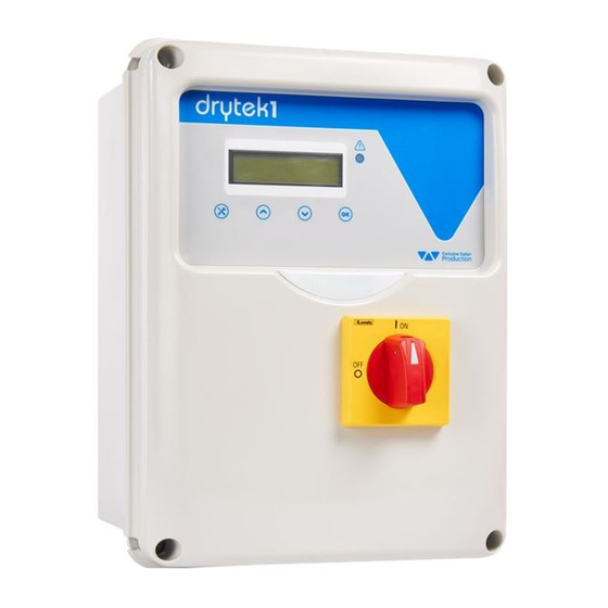
- Page 1 DRYTEK 1 - User Manual ELECTRICAL PANEL FOR 1 MOTOR WITH POWER FACTOR CONTROL...
-
Page 3: Table Of Contents
CONTENTS INTRODUCTION ...................... 5 WARNINGS ......................6 GENERAL DESCRIPTION ..................7 INSTALLATION ......................8 CONTROL PANEL ....................9 Luminous indicators and control commands ..............9 KEY TO FUNCTIONS AND SETTINGS ..............10 Main display items ......................10 Activation of load in manual mode ................10 User programming in automatic mode ................. -
Page 5: Introduction
If defects are found, the client should promptly notify our retailer within 5 days of receiving the goods, or in the event of direct purchases, the Elentek service center. N.B. the information provided in this manual is subject to modifications without notice. -
Page 6: Warnings
The electrical panel must be connected by a qualified electrician in observance of the relevant electrical standards. No parts of the panel must be disassembled without the official authorization of Elentek: any tampering with or modifications to the unit will render all terms of the warranty null and void. -
Page 7: General Description
3. GENERAL DESCRIPTION Power supply 1 ~ 50/60Hz 230V±15% (DRYTEK 1-Single); Power supply 3 ~ 50/60Hz 400V±15% (DRYTEK 1-Three); C/I1 normally open input for start-up command; Buttons for function selection and programming; Buttons AUTOMATIC-0-MANUAL (spring return); ... -
Page 8: Installation
Ensure that the mains power supply specifications correspond to the voltage specified on the data plate of the electrical panel and motor connected, then make the earthing connection before all other connections. ► DRYTEK 1 Mono 1~230V ± 15% 50/60Hz ► DRYTEK 1 Tri 3~400V ±... -
Page 9: Control Panel
5. CONTROL PANEL Luminous indicators and control commands The DRYTEK 1 electrical panel has been designed for the adjustable protection of 1 motor with dry running safety control, obtained from the power factor (where “fi” is the timing angle between current and voltage), without the need for external commands (float or pressure switch). -
Page 10: Key To Functions And Settings
E L E N T E K MODEL 50HZ DRYTEK v 2.0 www.elentek.com M/2.2 At the end of the start-up sequence, the main menu is displayed, as described below. This screen enables display of the electrical data as read by the DRYTEK 1 230V 0.0A 1.00 ϕ... -
Page 11: User Programming In Automatic Mode
User programming in automatic mode To access the user programming menu, press and hold the SETUP button until the first parameter settings menu is displayed (minimum power factor). Practical examples: ① Protection against dry run by motor cos φ . ②... - Page 12 6.3.1 MINIMUM POWER FACTOR (COS-FI) On access to the menu, the first window enables modifications to the MINIMUM COS-FI minimum power factor value, below which the load is deactivated due to 0.80 ϕ dry running conditions (use the arrows to modify the value). To go to the next window, press OK.
- Page 13 6.3.3 RESET In the event of a dry running alarm (minimum power factor) the panel may attempt to reset automatically, which can be programmable in minutes, with the option of setting this function as sequential. 4 reset times can be set, in which the system automatically restarts after RESET N.
- Page 14 6.3.4 SUMMARY SETUP TABLE DESCRIZIONE PARAMETRO VALORE DEFAULT MAXIMUM CURRENT This parameter enables entry of the maximum current for each motor. Enter the maximum current value, increasing it by 10-15% with respect to … the rated motor value. Modifications to operating limits beyond the parameters stated on the model data plate will immediately render the warranty null and void.
-
Page 15: Alarms
7. ALARMS The measured power factor value is the set value and the panel shuts down ALARM MOTOR the relative pump. The display blink and the cumulative alarm output is DRY RUNNING activated (voltage-free contacts NC-C-NO). The system resets automatically on the basis of the times set during programming, or manually by pressing the button SETUP until the screen is displayed without flashing, after which the button OK can be pressed to reset. -
Page 16: Assistance Menu Parameters
8. ASSISTANCE MENU PARAMETERS This menu is accessed by simultaneously pressing the buttons SETUP and OK during activation of the panel. This menu enables modifications to the language, minimum and maximum voltage, with the latter programmed by default as shown in the table below (modify only if absolutely necessary). IF YOU CHANGE THE OPERATING LIMITS, BEYOND THE DEFAULT PARAMETERS, WILL RESULT IN IMMEDIATE FORFEITURE OF THE GUARANTEE. -
Page 17: Standard Circuit Diagrams
9. STANDARD CIRCUIT DIAGRAMS DRYTEK 1 Single phase circuit diagram... -
Page 18: Drytek 1 Three Phase Circuit Diagram
DRYTEK 1 Three phase circuit diagram... -
Page 19: Standard Wiring Diagrams
10. STANDARD WIRING DIAGRAMS 10.1 DRYTEK 1 Single phase wiring diagram 10.2 DRYTEK 1 Three phase wiring diagram... -
Page 20: Standard Dimensional Diagram
11. STANDARD DIMENSIONAL DIAGRAM 11.1 DRYTEK 1 Single phase dimensional 11.2 DRYTEK 1 Three phase dimensional... -
Page 21: Troubleshooting
12. TROUBLESHOOTING PROBLEM CHECKS/SOLUTIONS Ensure that a jumper is wired in on input G/P, if a float or THE PANEL IS SET TO AUTOMATIC MODE BUT pressure switch is not connected. Ensure correct operation of the float or pressure switch THE PUMP DOES NOT START. -
Page 22: General Conditions
13.1 Warranty The product warranty is subject to the general terms of sale of the company Elentek S.r.l. Acknowledgement of the warranty depends on the strict and proven observance of the operating instructions in this booklet and application of the correct mechanical, hydraulic and electro-technical practices. -
Page 23: Declaration Of Conformity
14. DECLARATION OF CONFORMITY ELENTEK Srl with registered offices in via A. Meucci, 5/11 - 35028 Piove di Sacco (PD) ITALIA, declares under its sole responsibility that the machine: DRYTEK series installed and used in the ways and for the purposes described in the operation and instruction manual complies with the provisions of the EU directives and relative amendments: ... - Page 24 NOTES...
- Page 25 NOTES...
- Page 26 NOTES...
- Page 28 ELENTEK SRL SOCIETÀ UNIPERSONALE Via A. Meucci 5/11 - 35028 Piove di Sacco (PD) - ITALIA Tel. +39 049 9730367 - Fax +39 049 9731063 Cod. MQ 0003 UK www.elentek.com - info@elentek.com Rev. 01 P.IVA 04534630282 Em. 11.2016...
Need help?
Do you have a question about the DRYTEK 1 Mono and is the answer not in the manual?
Questions and answers