Table of Contents
Advertisement
Quick Links
Advertisement
Table of Contents

Related Manuals for Enko AMF 3.1

Summary of Contents for Enko AMF 3.1
- Page 1 AMF 3.1/EN/K.K./01 AMF 3.1 User Manual...
-
Page 2: Table Of Contents
AMF 3.1 USER MANUAL Table of Contents General Descriptions ....................................3 Connection Diagram ....................................4 Front Panel ......................................5 Rear Panel ....................................... 9 Terminal Connections ..................................9 Alarm Codes & Descriptions ................................11 Interface Structure ....................................14 MENU SCREEN STRUCTURE ................................16 P2-Alarm Log Screen .................................. -
Page 3: General Descriptions
By pressing the Menu button for 3 seconds, the user can edit and save any parameter among the 425 parameters in the unit. This feature allows AMF 3.1 to be easily adapted to any engine without the need of a separate unit. -
Page 4: Connection Diagram
AMF 3.1 USER MANUAL Connection Diagram 4/22... -
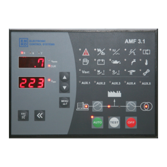
Page 5: Front Panel
AMF 3.1 USER MANUAL Front Panel Generator Status LED (1): Generator idle when the LED is off. Generator running when the LED is on The LED will be blinking during the failure delay time during Generator initial cranking and cool-down and stop delay timers during Generator stopping. - Page 6 AMF 3.1 USER MANUAL Mains Status LED (6): When off, the Mains values are outside the limits set by the parameters. When lit, the Mains values are within the limits set by the parameters. The LED will be blinking while switching from Mains Normal condition to Mains Failure condition or while switching from Mains Failure condition to Mains Normal condition which will be exlpained below.
- Page 7 AMF 3.1 USER MANUAL Selection Button: While in normal operation this button has the same function as the button above. While in parameter menu, after pressing the Enter Button and selecting a parameter to edit, the desired digit can be selected by using this button, each press will shift the selected digit to the right.
- Page 8 AMF 3.1 USER MANUAL the Mains by pressing the Mains Contactor Status Button . The Load can be idled by pressing the Mains Contactor Status Button again. OFF Operation Mode: When the OFF button is pressed the AMF will stop executing the Generator and Mains control functions and enter sleep mode.
-
Page 9: Rear Panel
AMF 3.1 USER MANUAL Rear Panel Terminal Connections TERMINAL TERMINAL NAME DESCRIPTION The positive terminal of the battery must be connected. The value of the terminal must be BATTERY + between 9 – 30V. The negative terminal of the battery must be connected. The negative terminal of the battery BATTERY - should be grounded. - Page 10 AMF 3.1 USER MANUAL Terminal connection is empty, please do not make any connections. Terminal connection is empty, please do not make any connections. Terminal connection is empty, please do not make any connections. Analog oil pressure sender is to be connected to this terminal. The settings related to this OIL PRESURE SEND.
-
Page 11: Alarm Codes & Descriptions
AMF 3.1 USER MANUAL COM PORT Used for ENKO Pro-Link SCADA PC connection Important Note: For the Low Oil Pressure digital Input, the related activation time must be set a “2”. When this input is assigned, the check will be made after the engine has started regardless of the failure activation time. - Page 12 AMF 3.1 USER MANUAL It indicates “Low Battery Voltage Alarm”. F20 is displayed when the battery voltage is less than or more than the set values. (see: P47: Battery Voltage Failure Lower Limit, P48: Battery Voltage Failure Upper Limit). It indicates “Mains Circuit Breaker Feedback Failure Alarm”.
- Page 13 AMF 3.1 USER MANUAL It indicates “Generator Self-start Alarm”. If the engine is started by an external source other than AMF 3.4, an alarm will NOT be signaled. However if the engine is attempted to start when the AMF is in AUTO or TEST operation modes while the engine is already running, this alarm will be activated.
-
Page 14: Interface Structure
AMF 3.1 USER MANUAL F34,F35,F42 Feedback Alarm, GCB Feedback Alarm, Thermic Alarms can be auto- F43,F45 acknowledged. Parameter P221 is inactive in an Earthquake or Emergency situation. F16,F17,F21 Depends on the function assigned to Aux. Input 4. Oil Switch, High... - Page 15 AMF 3.1 USER MANUAL Row: V Voltage. Please see Note 1. Row: Blank Row: V Voltage. Please see Note 1. Row: Blank Row: V Voltage. Please see Note 1. Row: Blank Row: V Voltage. Please see Note 1. Row: Blank Row: V Voltage.
-
Page 16: Menu Screen Structure
In order to view/edit paramters, the alarm log, the engine running hours and maintenance timers, the menu must be entered. To enter the AMF 3.1 menu, press and hold the Menu Button for 3 seconds while in measurement display mode. - Page 17 AMF 3.1 USER MANUAL The AMF 3.1 menu consisit of 3 main categories which are: P1 PAR: Parameter edit screen P2 ALR: Alarm log screen P3 SER: Maintenance timers screen The desired category can be selected using the Up and Down Arrow buttons.
-
Page 18: P2-Alarm Log Screen
AMF 3.1 USER MANUAL P2-Alarm Log Screen Screen Description The alarm log screen is the 2 page that appears in the menu and can be navigated by pressing the Up and Down buttons, and pressing the Menu button on the “P2 ALr” screen. The alarm log screen displays the code, date and stamp for the last 15 alarms in the system. -
Page 19: Digital Input Functions & Descriptions
AMF 3.1 USER MANUAL there are 1200 hours left until general maintenance. The second timer is the Engine Maintenance Timer and is indicated as “Eng” as seen on the screen on the left. A few seconds after this indication the second screen seen on the left will appear. The screen indicates that there are 1200 hours left until engine maintenance. - Page 20 AMF 3.1 USER MANUAL The sender which energizes once the coolant level drops below a certain 3: Coolant Level Switch limit is to be assigned this function. If a signal is received, the alarm is sensed and AUX. 1 led found on the 4: Aux.
-
Page 21: Digital Output Functions & Descriptions
AMF 3.1 USER MANUAL screen, the input is re-enabled. 25: Undefined No function is assigned. AMF31 cihazı üzerindeki Arıza Sil (Korna Sustur) tuşunun fonksiyonluğunu yerine getirir. Bu giriş 0’dan 1’e geçiş sırasında algılanır. 26: Alarm Acknowledge Button Function Seviye algılanmaz. -
Page 22: Document Version
AMF 3.1 USER MANUAL activated. If the system is fed through the mains contactor, this output will be 9: Mains Loaded Output activated. If there is a requirement of automatic fueling this output will be activated. If the fuel level drops below the limit set by parameter P300 this output is...
Need help?
Do you have a question about the AMF 3.1 and is the answer not in the manual?
Questions and answers
HI , we have ENKO , Contorl on one of DG , our DG stooped in 2 min and some time in 10 min ,please help me to solve defects