Table of Contents
Advertisement
Quick Links
Advertisement
Table of Contents

Related Manuals for Metrima SVM F4


Summary of Contents for Metrima SVM F4
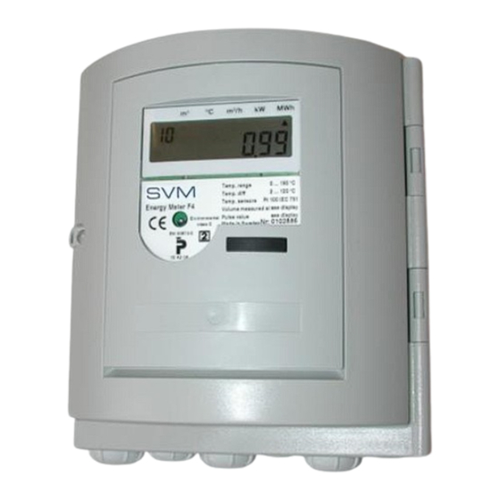
- Page 1 SVM F4 Calculator Manual...
-
Page 2: Table Of Contents
Calculator F4 manual GENERAL DISPLAY Installation Back-light Principle of energy measurement Display test 1.2.1 Alternative naming Display modes Calculator specifics 3.3.1 Transport mode 1.3.1 Monthly values 3.3.2 Initial mode ( INIT mode) 1.3.2 Account days 3.3.3. Service Mode 1.3.3 Pulse counter register 1 and 2 3.3.3.1 Service/INIT mode sequence 13 1.3.4... - Page 3 TESTING, PROGRAMMING & Battery and mains connection SERVICE Calculator connection Programming the calculator Mains connection and backup Display test battery Installation test Option board handling 5.6.1 Option board installation Service procedure 7.4.0 Time 5.6.1.1 Installing several option 7.4.1 Date boards at the same time 7.4.2 Pulse value 5.6.2...
-
Page 4: Calculator F4
1 General Installation The calculator is delivered set in “Transport mode”, but depending on delivery options the calculator can be delivered in other “display modes”, e.g. “Transport mode”, see display modes for more information. Follow this procedure to install the calculator: Setting of calculator, see “Service, setting meter”... -
Page 5: Principle Of Energy Measurement
Principle of energy measurement A BB 1.2.1 Alternative naming The nomenclature for the energy industries are not unified, different words are used to explain the same things. The words recommended are under- lined. Calculator, Heat meter or meter Flow sensor: Supply, forward, hot and high. - Page 6 1.2.3 Operating conditions All electronics have limitations like response time, in memory capacity and so on. In order for the battery consumption and for trouble free usage of the calculator following limitations apply for the F4, see below. 1.2.3.2 Limitations mains supplied 1.2.3.1 Normal operating conditions for battery supplied calculators The M-Bus reading frequency must not exceed...
-
Page 7: Calculator Specifics
“FlexServ version 2”. Note: Only by Account day 1: 1 January (0101) Account day 2: 1 July (0701) authorized personnel from Metrima AB. The values for the account day will be stored at the See also 3.3.5.1 table 3.2 for more information on day shift. -
Page 8: Placing Of Flow Sensor
1.3.3 Pulse counter register 1 and 2 1.3.6 Communication address The calculator has two (2) pulse inputs that acts as The calculator has two (2) communication add- volume accumulators in [m³]. To set the volume resses in M-Bus. accumulators to pulse counters the pulse weight in Primary address, this is a value from 1-250. -
Page 9: Buttons And Jumpers
2 Buttons and jumpers Push button Test button The calculator is equipped with a “Push button”. This button is used in combination with holding the With the “Push button” the user can toggle between “Push button” to set calculator into test mode. different values on the display at the display Tool: Test key sequence the calculator is in at the moment. -
Page 10: Jumpers J1, J2, J3
Jumpers 2/4-Wire method Slot jumpers for temperature sensors Signal/Power redirecting On the slots “C” and “D” there are jumpers for The F4 is by default configured for 2-wire measuring method connection for temperature redirecting power and bus signals. When these are sensors. -
Page 11: Display
3 Display The F2/3/4 calculators are equipped with a LCD (Liquid crystal display). The units on display label and decimal placing is different depending on calculator configuration. See also clarification of display fig. 3.1: 1. Display sequence, in this case “10”, default position, (the position the calculator returns to after 60 seconds of “push-button”... -
Page 12: Display Modes
3.3.2 Initial mode ( INIT mode) Display modes The calculator enters the INIT mode after exiting The calculator can be set in different display modes the transport mode (this can vary depending on depending on what data that shall be accessed in the setting of the calculator). -
Page 13: Service Mode
“0A” appears. Replacement of battery date, YYMMDD Do not change without consulting 2. Release the “Push button” Metrima AB Exit service sequence, 3. Press “Push button” once to change the 1 = Exit value digit to “1” (exit INIT mode). -
Page 14: Test Mode (Programming Mode)
Do not use the service program without proper education consulting Metrima AB. Warning 2: When programming the F4 only use Fig 3.6, Display in test mode, “flash” in display Service program version 2.0 or high- er, otherwise the calculator will be... -
Page 15: Normal Mode ( Operating Mode )
3.3.5 Normal mode ( operating mode ) Normal mode is the calculators operating mode. In this mode the calculator accumulates energy, calculates and makes measurements. The calculator can also communicate by using M-Bus or SIOX protocols (SIOX only with an extra option board). Display sequences The first digit from left is the sequence number, see also fig. -
Page 16: Display Sequence Normal Mode
3.3.5.1 Display sequence normal mode Description Accumulated energy (Default position) Accumulated volume according to flow sensor Display test, see fig.3.2 Accumulated volume for pulse input 1, [m Accumulated volume for pulse input 2, [m Error code, see Error code Error time, [Minutes] Momentary power Momentary flow High temperature, 0 decimals... -
Page 17: Display Sequence Normal Mode
3.3.5.2 Display seq. normal mode 2 ID Option card A Status option card A ID Option card B Status option card B ID Option card C Status option card C ID Option card D Status option card D ID Option card E Status option card E ID Option card F Status option card F... -
Page 18: Display Sequence Normal Mode Schematics
3.3.5.4 Display sequence normal mode schematics Default How to: position To change sequence HOLD the “Push button” until the display changes sequence. To change values within a specific Loop to next sequence PUSH “Push button” until account day the display changes value. Loop back to next monthly register Only when option... -
Page 19: Error Codes
Error codes Sometimes an error code will appear in display sequence 15, 37, 47, 74 and on M-Bus. The error code message can be interpreted using the table below. The error codes consist of three (3) hexadecimal (Hex) digits, e.g. 0 – 15. Each digit can have up to 4 different error codes in combination. -
Page 20: Seals, Calculator Protection
4 Seals, calculator protection The F2/3/4 are tampering protected with seals. To enter the calculator or to enter “Test mode”, “Service mode” or to enter the electronics inside the calculator several seals need to be broken, see placement of the seals below: Fig 4.1, F2 Placement of seals Seals 1. -
Page 21: Connecting The Calculator / Handling
5 Connecting the calculator / handling The figure below shows the main circuit board of F4. The “2” indicates main circuit board for F4. Note: Only option boards marked with “2” may be installed in calculator F4. Circuit board F4 Facaed side aligned... -
Page 22: Connection Terminals
Connection terminals 5.2.1 Sensors and M-Bus connection The connections of temperature sensors are shown 5.2.1.1 EN1434 terminal table in figure 5.2 and table 5.1, numbering in See fig. 5.2 and 5.2b, Potential free output 5.2.8 and accordance to EN1434. Mains 5.5 Termi Warning;... -
Page 23: Pulse Input Connection
5.2.2 Pulse input connection 5.2.4 Connection 3V/12V The calculator can accumulate pulses from other The calculator can supply an external device with meters, such as electricity meters, cold and warm 3V/12V, with 20mA in total, see fig 5.12. The 12V connection exists only in mains powered calculators water meters and gas meters. -
Page 24: Save Data
5.2.5 Save data 5.2.7 Option board connection By short short-circuiting the “Save data” button The terminals marked A, B, C, D and E are using the plastic “Test key” the calculator will store connection for the option boards, please see option the measured values to an EEProm. -
Page 25: Battery And Mains Connection
Battery and mains Mains connection and connection backup battery There are two wires connecting the main circuit The F4 are normally delivered with mains, and board to the power supply boards, Battery “K3” and backup battery. (Only applies to mains version of Mains “K2”, for connection, see fig. -
Page 26: Option Board Handling
When uncertain check with option documentation or Metrima AB when using a board documentation. calculator only powered by batteries. 6. Check dipswitch settings on option board. Insert the option board into the calculator 5.6.1.1 Installing several option... -
Page 27: Dip-Switch Setting Of Option Board
5.6.2 DIP-Switch setting of option 5.6.6 Uninstall, removal of option board boards or reconfiguring option boards Slot BY 1 BY 2 BY 3 To uninstall, reconfigure one or several option boards, all option boards in calculator must be removed and the “uninstall procedure” executed by the “uninstall option board”. -
Page 28: Cable Fittings
Cable fittings The F3/4 are equipped with cable glands see fig. 5.6, below. PG11 PG11 PG11 Ø6 - 10 Ø5 - 8 Ø6 - 10 Ø3.5 - 6 Ø6 - 10 Ø3.5 - 6 Fig 5.6, Cable fittings F3/4 Mounting The F3/4 is constructed for wall mounting, see below fig 5.7. -
Page 29: Zero Sequence Current
Zero sequence current When connecting the calculator to input or outputs one need to be aware of the possibility of “Zero sequence current” can cause problems in the input/output systems, such as no signals, error readings, parity errors and in worst case damaged circuits in the system. -
Page 30: Calculation Of Flow
6 Calculation F4 calculator is in accordance with EN1434:1997, part 1 and 2, measuring and calculating energy. 6.1.1 Momentary flow calculator fulfils the requirements The momentary flow is calculated at the end of an environmental class C, in accordance with averaging period of 4 seconds, normally set in the EN1434:1997 part 4 calculator. -
Page 31: Calculation Of Power
Calculation of power Storing values The calculated flow, see above is used by the meter The calculator stores the measured values at each dayshift (at 00:00 each day) or when “Save data” to calculate the power and this value is added to the previously stored power values. -
Page 32: Testing, Programming & Service
7 Testing, programming & service To ensure the functions in the F3/F4 test can be performed. Programming the calculator Display test The calculator parameters can be configured by By selecting display sequence “12” the LCD entering the calculator “Service mode” or “INIT mode”, see Service 7.4. -
Page 33: Service
7.4.6 Communication address Service (primary address) When calculator is in for service there can be a necessity to change the calculator configuration. The primary communication address can be These parameters can be changed in the “Service changed in display sequence “06”. The communi- mode”, se below for detailed information. -
Page 34: Verifying The Calculator
Verifying the calculator Verification of the calculator's measurement To leave test mode proceed as follows: accuracy is undertaken in the test mode, where the While the short circuit the test button hold the energy value/flow sensor pulse is issued via the “Display Button”, see fig.2.2. -
Page 35: Technical Data
8 Technical data Data output table The following data are accessible via the data output: M-Bus SIOX Manu- Data acc. EN SVM820 Ext- factures 60870-5 ended Specific Flow sensor placing Program version Manufacturer Communication address Meter number Error code (limited) Accumulated energy Accumulated, volume 1 Accumulated, volume 2... -
Page 36: Power Supply
Power supply Flow sensor placing 3.6V – F2/3/4 can be configured for flow sensor placed in Battery 2.750Ah or 3.6V – 2x 2.750Ah hot or cold pipe (supply or return pipe). This is Operation time max. 10 years marked H = hot or L = Low in the display. Mains 230V±10%, 45-65Hz, battery 2.750 Ah as a spare... -
Page 37: Pulse Outputs
8.11 Pulse outputs 8.13 Alarm output F3/4 are equipped with two pulse outputs as The F4 is equipped with one alarm output as standard of the type ”Open collector” for energy standard of the type “Open collector”. The alarm (Pulse output 1) and volume (Pulse output 2). The output sends a pulse every hour as long as an error pulse outputs can be galvanic separated from the code exists. - Page 38 Appendix Decimal setting for F2/3/4 Pulse value m³ MBTU m³/h [l/p] 0.001 0.001 0.001 0.001 0.01 0.001 0.01 0.01 0.01 0.01 0.01 1000 0.001 0.01 0.01 0.01 0.01 0.001 0.01 0.01 2500 Table A1, The options marked “-“ should not be used. For the pulse inputs the decimal setting follow the same table setting as for the volume register [m Decimal settings for F2/3/4 pulse inputs Pulse...
- Page 39 © Metrima AB Stockholm, Sweden Created date: 2000-10-11 Created by: Johan Tsung / U Rev. date 2005-03-09 Rev. by: MaSj Revision no.: 1.077 Filename : F4 Manual [3-04-01 E].doc Metrima AB www.metrima.se info@metrima.se Norra Stationsgatan 93 SE-113 64 Stockholm Phone: +46 8 23 60 30 Fax: +46 8 23 60 31...
Need help?
Do you have a question about the SVM F4 and is the answer not in the manual?
Questions and answers