
Related Manuals for CPC MultiFlex RTU


Summary of Contents for CPC MultiFlex RTU
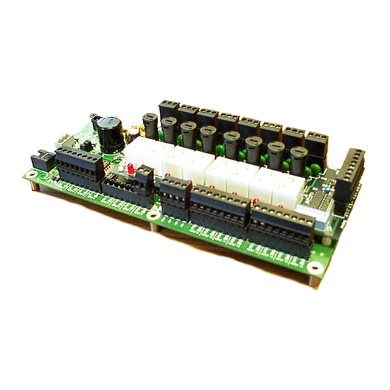
- Page 1 026-1706 Rev 1 10-29-02 MultiFlex RTU Rooftop Controller Installation and Operation Manual...
- Page 3 If the equipment is not used in the manner specified by the manufacturer, the protection provided by the equipment may be impaired. SAVE THIS INSTRUCTION MANUAL This instruction manual contains important operating instructions for the MultiFlex RTU rooftop control board.
-
Page 5: Table Of Contents
2.3.1. Choosing Transformer Sizes ..........................4 2.3.2. MultiFlex RTU Power Wiring..........................4 2.3.2.1. New-Style MultiFlex RTU Boards (with Isolated Power Supply) ..................4 2.3.2.2. Old-Style MultiFlex RTU Boards No Isolated Power Supply) ..................5 2.3.3. Wire Types and Maximum Distances........................6 2.4. - Page 6 ALVE ONTROL 6.8. S ............................21 TAND LONE PERATION 6.9. S ..............................22 ENSOR AILURES 7 THE MULTIFLEX RTU HAND-HELD INTERFACE................... 23 7.1. RTU H ......................23 ERMINAL TATUS CREENS 7.2. RTU M ............................... 24 7.3. S ................................24 TATUS 7.4.
-
Page 7: Overview Of The Multiflex Rtu
(P/N 810-3062) is a “smart” combination input/ output board designed to control package roof- The RTU can control a rooftop unit indepen- top HVAC units. The MultiFlex RTU is capable dently without the need of a central controller of controlling heat and cool stages, fans, humidi- (such as CPC’s Einstein BX Refrigeration Con-... -
Page 8: Mounting And Powering
Figure 2-1 - MultiFlex Snap-Track Mounting Figure 2-2 provides mounting dimensions for the MultiFlex board. Figure 2-2 - MultiFlex Board Dimensions 2 • MultiFlex RTU Operator’s Guide 026-1706 Rev 1 10-29-02... -
Page 9: The Plug-In Output Board
The additional board makes the MultiFlex 2.2. The Plug-In Output RTU boards considerably taller than the Multi- Flex 16 and other CPC I/O boards. If you will be Board mounting these boards in an enclosure, the board will need at least 2.5" of clearance between the base board and the panel door. -
Page 10: Choosing Transformer Sizes
MultiFlex Board (Top Left Corner) 2.3.2. MultiFlex RTU Power Wiring The MultiFlex RTU boards do not use a cen- ter tap. Instead, the 0V terminal on the board Figure 2-4 - New-Style vs. Old-Style MultiFlex Board should be connected to a separate Earth ground. -
Page 11: Old-Style Multiflex Rtu Boards No Isolated Power Supply)
MultiFlex board can be connected to any of Transformers With a Center Tap the center-tapped transformers mentioned in In addition, the MultiFlex RTU boards can Table 2-2, provided you follow the following be powered by one of the 50VA or 75VA non-... -
Page 12: Wire Types And Maximum Distances
14 AWG: board. Feet = 0.25/(VA/24) x 0.00252 18 AWG: In addition, the old-style MultiFlex RTU Feet = 0.25/(VA/24) x 0.0064 boards can be powered by one of the 50VA or (VA is the total VA rating of the I/O boards) 75VA non-center-tapped transformers listed in Table 2-1 on page 3. -
Page 13: The Multi Flex Rtu Battery And Battery Enable Jumper
ENABLE position (UP) before instal- 2.4. The MultiFlex RTU Bat- lation. To preserve battery life, when storing the MultiFlex RTU, the jumper should be set to the tery and Battery Enable DISABLE position. Jumper The RTU uses battery-backed memory to store set points and the current time and date. -
Page 14: The I/O Network
A diagram of this network arrangement is shown in Figure 3-1. Although the MultiFlex RTU can operate as a stand-alone controller, it relies on an Einstein or REFLECS unit for advanced features such as remote dial-in/dial-out, logging, and alarm con- trol. -
Page 15: Numbering The Multiflex Rtu
Either may be used — refer to your site controller’s user manual for the baud rate recom- The MultiFlex RTU is a unique board type mendation (currently 9600 baud for both on the RS485 Network by the CPC controllers. -
Page 16: Rtu Input And Output Setup
Configurable in RTU software (see Section 4.1.2., Auxiliary Input Types) Figure 4-1 - MultiFlex RTU Input Locations Table 4-1 - RTU Default Inputs The MultiFlex RTU has pre-defined loca- 4.1.2. Auxiliary Input Types tions for connection to all sensors that are typi- cally present for a rooftop unit. -
Page 17: Wiring Sensors To The Multiflex Rtu
Code Auxiliary Input Type Description Code Auxiliary Input SMOKE STAT A smoke alarm Type Description DIRTY FILTER A digital device that de- MIXED AIR Temperature sensor mea- tects blocked filter condi- suring the temperature of tions air from the economizer TEMP General temperature sen- mixed with the return air. -
Page 18: Input Type Dip Switches
RIGHT (ON) position. +5VDC points. See Figure 4-5 for the location of these points. Figure 4-3 - Input Type Dip Switches for RTU Board Figure 4-5 - Input Board Power Sources 12 • MultiFlex RTU Operator’s Guide 026-1706 Rev 1 10-29-02... -
Page 19: Current Ratings For On-Board Power Sources
24VAC signal isolated from its DC output The MultiFlex RTU has pre-defined loca- signal (such as CPC’s Dew Point Probe). If the tions for connection to all outputs that are typi- output signal is not isolated from the 24VAC cally present for a rooftop unit. -
Page 20: Multiflex Rtu Auxiliary Output Types
Table 4-4 - Auxiliary Output Types analog economizer 4.2.3. Wiring Outputs to Points Table 4-3 - RTU Default Outputs The MultiFlex RTU has Form C relay con- 4.2.2. MultiFlex RTU Auxiliary Out- tacts. Figure 4-7 shows how to wire the three- put Types terminal Form C contact. -
Page 21: Output Fail-Safe Dip Switches
4.2.4. Output Fail-Safe Dip Switch- Table 4-5 and Table 4-6 show how the fail- safe switch and Form C contacts should be con- figured based on how you want the output to When a controller calls for a MultiFlex relay perform during both normal operation and dur- output to be ON, it sends a command to the Mul- ing network/power loss. -
Page 22: Analog Outputs
4.3. Analog Outputs Figure 4-8 - MultiFlex RTU Analog Output Locations The MultiFlex RTU analog outputs are +0- +10VDC points used for controlling variable- position economizers and variable-speed fans. The maximum output current for each point is 10 milliamps. Unlike most of the RTU inputs and outputs, the two analog points are not pre-defined. -
Page 23: Board Status Leds
5.3. The Code A LED 5.2. Tx and Rx LEDs The Code A LED on the MultiFlex RTU indicates activity on the Hand-Held Terminal The Tx and Rx LEDs indicate when the Mul- port. When this LED is not blinking, it means no tiFlex is sending or receiving messages on the HHT is plugged into the board. -
Page 24: The Codeb Led
OFF. The definition of ON and OFF in this case is determined by the position of the fail-safe dip switch (see Table 4-5 and Table 4-6). 18 • MultiFlex RTU Operator’s Guide 026-1706 Rev 1 10-29-02... -
Page 25: Software Overview
Software Overview 6.2.1. Set Points There are two active set points in an RTU: a cooling set point and a heating set point (both of which are supplied by the zone from the Einstein 6.1. Introduction to Zone or BCU). When the input rises above the cooling Control set point, cooling mode begins, and when the input falls below the heating set point, heating... -
Page 26: Fan Control
If economiza- probe input connected to the central building tion is OK, it sends an ENABLE signal to its 20 • MultiFlex RTU Operator’s Guide 026-1706 Rev 1 10-29-02... -
Page 27: Analog Economizers
AHU Zone applications. For as long as the 6.7. Reversing Valve Control ENABLE signal lasts, AHU Zone applications treat the economization dampers as if they are preliminary cool stages; if cooling is needed, the If reversing valves are used, the AHU Zone applica- dampers will open and economization will tion will not be allowed to bring on stages of heat to compensate for cool stage activation during dehumidi-... -
Page 28: Sensor Failures
Comparison” is the chosen method of econo- mization enabling. In this case, economization will be disabled for both normal and stand-alone operation. A failure alarm will be generated and sent to the Alarm Advisory Log. 22 • MultiFlex RTU Operator’s Guide 026-1706 Rev 1 10-29-02... -
Page 29: The Multiflex Rtu Hand-Held Interface
HHT. To change the value in a field, press the RIGHT arrow key. A cursor will appear in the screen next to the first change- RTU Hand-Held Terminal Status Screens The MultiFlex RTU Hand-Held Interface • 23... -
Page 30: Rtu Main Menu
Timer: Number of minutes left on the Make-Up Air timer. The number in pa- Timer 000 (10) renthesis is the defined Make-Up Air set point. Dampr Offset 000 Dampr Offset: Percentage of damper offset during makeup mode. 24 • MultiFlex RTU Operator’s Guide 026-1706 Rev 1 10-29-02... -
Page 31: Control Menu
76 80 Dead bands, on delays, and off delays for heating and cooling set points may DEAD DELAYS be viewed and changed at this screen. BAND ON OFF 03 00 03 01 Control Menu The MultiFlex RTU Hand-Held Interface • 25... - Page 32 By default, the outputs will MINV MAXV 00.0 10.0 modulate from 0-10VDC. To specify a different voltage range, enter values 00.0 10.0 in the MINV and MAXV fields. 26 • MultiFlex RTU Operator’s Guide 026-1706 Rev 1 10-29-02...
- Page 33 Reset Setpts message and pressing the dash key. The letters “CL” will appear. To con- firm the alarm reset, press ENTER; to cancel the runtime reset, press the pe- riod “.” key. Control Menu The MultiFlex RTU Hand-Held Interface • 27...
Need help?
Do you have a question about the MultiFlex RTU and is the answer not in the manual?
Questions and answers