
Related Manuals for Monnit MNG2-9-EGW-CCE


Summary of Contents for Monnit MNG2-9-EGW-CCE
- Page 1 Monnit Ethernet Gateway 4 User Guide IMPORTANT! For best results, please wait to power on your Ethernet Gateway 4 until after you have registered an account on iMonnit and added your gateway and sensors to the online system.
-
Page 2: Table Of Contents
Table of Contents I. ABOUT THE ETHERNET GATEWAY 4 ALTA ETHERNET GATEWAY 4 FEATURES EXAMPLE APPLICATIONS II. HOW YOUR GATEWAY WORKS III. GATEWAY SECURITY SENSOR COMMUNICATION SECURITY DATA SECURITY ON THE GATEWAY SERVER COMMUNICATION SECURITY SNTP SECURITY SNMP SECURITY IV. GATEWAY REGISTRATION REGISTERING THE ETHERNET GATEWAY 4 V. -
Page 3: Alta Ethernet Gateway 4 Features
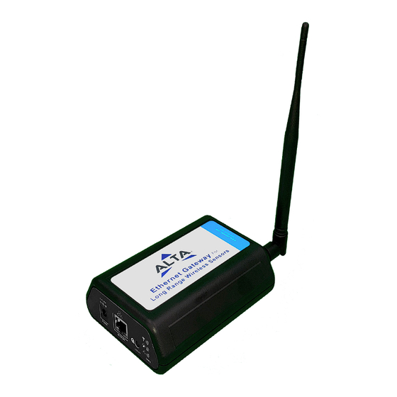
Internet connection. The Ethernet Gateway 4 allows your Monnit Wireless Sensors to communicate with the iMonnit system via Ethernet transmission. ALTA Ethernet Gateways are advanced wireless IoT gateways that enable fast time-to-market solutions. Monnit’s Ethernet Gateway 4 is... -
Page 4: How Your Gateway Works
II. HOW YOUR GATEWAY WORKS Your ALTA Ethernet Gateway 4 manages communication between your sensors, iMonnit, and network peers through the SNMP v1 and Modbus TCP protocols. When running, the gateway will periodically transmit data on a heartbeat to the iMonnit servers. The gateway will store information received from sensors until its next heartbeat. -
Page 5: Gateway Security
ISP. Incorrect time can affect the delivery of sensor traffic. If the Monnit Server is active, it will be utilized for time synchronization in ordinary opera- tion. So SNTP will be used as a backup. -
Page 6: About The Ethernet Gateway
If you have already created an account, start by logging in. For instructions on how to register for an iMonnit account, please consult the iMonnit User Guide viewable at monnit.com/support/documentation. REGISTERING THE ETHERNET GATEWAY 4 To register your gateway on iMonnit, you will need to enter the Device ID and the Security Code from your Ethernet Gateway 4 in the corresponding text boxes. -
Page 7: Understanding The Ethernet Gateway 4 Lights
V. USING THE ETHERNET GATEWAY 4 USING THE ETHERNET GATEWAY 4 The back of your gateway will look like the diagram below: From left to right, we see: Power: This is where your power cord will be plugged into. Network: This is the socket where your Ethernet cord will go. Utility Button: A short, five second, press of this button will enable the local interface. -
Page 8: Ethernet Gateway 4 Settings
ETHERNET GATEWAY 4 SETTINGS ON IMONNIT The Ethernet Gateway 4 will receive data from all sensors assigned to the network and within range, then return this data to the iMonnit server in a series of heartbeats. You can access gateway settings by selecting “Gateways” in the main navigation panel. Choose the Ethernet Gateway 4 from the list of gateways registered to your account. - Page 9 Commands Choose the bullet for Commands located just under the Settings title to access the commands page. A. Selecting the Reform Network command will trigger the gateway to remove all sensors from the internal whitelist, and then request a new sensor list from the server. This command will force all sensors to reinitialize their connection with the gateway.
- Page 10 Local Area Network Choose the Local Area Network bullet under the Settings title to open up the local area network configuration page. The Local Area Network includes the ability to switch your network IP address from DHCP to Static. DHCP will be the default network IP address. Multiple interfaces can be active, if using any of the polling interfaces we recommend using a static IP address on the Gateway.
- Page 11 SNMP Interface – SNMP stands for Simple Network Management Protocol) is an Internet application protocol that manages and monitors network device functionality. Monnit uses SNMP version 1. These settings can both be configured both on iMonnit and the local interface.
- Page 12 Modbus Interface – Modbus TCP (Transmission Control Protocol) is the Modbus RTU protocol with a TCP interface that runs on Ethernet. Monnit provides the Modbus TCP interface for you to pull gateway and sensor data. You can use Modbus without the server interface active.
-
Page 13: Using The Local Interface
VI. USING THE LOCAL INTERFACE If using iMonnit is not an option, you can set up your gateway and sensors offline through the local interface. • Connect the gateway to a router or network swtich using an Ethernet cord. • Plug in the gateway to a power outlet. -
Page 14: Gateway Options Tab
Data Interface Statuses Gateway data cache used - This percentage represents the amount of internal flash mem- ory storage for holding sensor messages has been used out of the maximum (896 kB). Messages sent from wireless sensors are stored temporarily in the gateway cache until a data interface (i.e. - Page 15 Selecting the “Reform Wireless Network” button will remove all devices from the current Wireless Device List. System Time Configuration Simple Network Time Protocol (SNTP) synchronizes computer clocks on a network when the Monnit Interface is unavailable. PAGE 13...
-
Page 16: Data Interfaces Tab
Epoch between Default Server and SNTP: This is the difference in seconds between the standard NTP Epoch (start date 01/01/1900) and Monnit’s Epoch (start date 01/01/2012). System Reset Period: The time in hours it takes for the system to reset. - Page 17 Modbus Transmission Control Protocol Configuration Modbus TCP interface runs on an Ethernet connection. TCP makes sure all data is received. Modbus TCP is a non-streaming data interface standard. This means data must be requested in order for it to be received. The Modbus TCP Interface will store all data values in 16-bit registers.
- Page 18 GATEWAY HOLDING REGISTERS Field Description Register Data Address Gateway ID_High The first 16 bits of a 32-bit serial ID number. 40001 Gateway ID_Low The last 16 bits of a 32-bit serial ID number. 40002 Gateway Version The gateway firmware Revision and Major version numbers (1 40003 Revision + Major byte each)
- Page 19 SNMP Configuration SNMP (Simple Network Management Protocol) settings for a gateway can be adjusted on the offline local interface. You can continue to use SNMP without the server interface active. The data will not be sent to a server, but you can continue to poll for the data as it is received by the gateway.
- Page 20 • Inbound Port – This is the number for where specifically in the server data from the gateway is received. • SNMP Community String – This is used to support SNMPv1 protocol by giving access to a router’s or other device’s statistics. The default will be set to “public.” Trap Settings Trap IP Address –The IP Address for the SNMP Server where the trap will be sent.
-
Page 21: Support
If any software or firmware incorporated in any Product fails to conform to the warranty set forth in this section, Monnit shall provide a bug fix or software patch correcting such non-conformance within a reasonable period after Monnit... - Page 22 (c) Monnit’s sole obligation under the warranty described or set forth here shall be to repair or replace non-conforming Products as set forth in the immediately preceding paragraph, or to refund the documented purchase price for non-conforming Products to customer. Mon- nit’s warranty obligations shall run solely to customer, and Monnit shall have no obligation...
-
Page 23: Certifications
• Connect the equipment into an outlet on a circuit different from that to which the reciever is connected. • Consult the dealer or an experienced radio/TV technician for help. Warning: Changes or modifications not expressly approved by Monnit could void the user’s authority to operate the equipment. RF Exposure... - Page 24 Canada (IC) English Under Industry Canada regulations, this radio transmitter may only operate using an anten- na of a type and maximum (or lesser) gain approved for the transmitter by Industry Canada. To reduce potential radio interference to other users, the antenna type and its gain should be so chosen that the Equivalent Isotropically Radiated Power (E.I.R.P.) is not more than that necessary for successful communication.
- Page 25 303 River Road 3400 South West Temple Ottawa, ON, Canada Salt Lake City, UT 84115 There is no restriction for the commercialisation of Monnit and ALTA 868MHz and 433MHz wireless products in all the countries of the European Union. PAGE 23...
- Page 26 All the relevant information’s is available on the European Community website: http://ec.europa.eu/enterprise/sectors/rtte/documents/ Additional Information and Support For additional information or more detailed instructions on how to use your Monnit Wireless Sensors or the iMonnit Online System, please visit us on the web at monnit.com/support. Monnit Corporation...
Need help?
Do you have a question about the MNG2-9-EGW-CCE and is the answer not in the manual?
Questions and answers