
Related Manuals for WorkSmart WS-MH-LFTB2-101


Summary of Contents for WorkSmart WS-MH-LFTB2-101
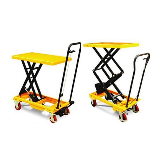
- Page 1 Instruction Manual Lift Table WS-MH-LFTB2-101 - WS-MH-LFTB2-104 - WS-MH-LFTB2-106 Note: Owner/Operator must read and understand this instruction manual before using the lift table.
-
Page 2: Table Of Contents
Contents WARNING CAUTION NAME OF PARTS HOW TO ASSEMBLE DAILY INSPECTION OPERATING LIFTTABLE 6. LIFTTABLE SPECIFICATIONS SERVICE INSTRUCTION HYDRAULIC CIRCULT SPARE PARTS LIST TROUBLES SHOOTING... -
Page 3: Warning
BEFORE OPERATING THE LIFT TABLE, READ THIS MANUAL CAREFULLY AND UNDERSTAND COMPLETELY. KEEP THIS MANUAL ON FILE FOR FUTURE REFERENCE. IF THIS IS LOST, PLEASE CONTACT YOUR LOCAL SUPPLIER FOR A NEW COPY. ALSO, IF THE WARNING/CAUTION DECAL ON THE UNIT IS LOST, PLEASE CONTACT YOUR LOCAL SUPPLIER FOR A NEW DECAL. -
Page 4: Name Of Parts
3. NAME OF PARTS WS-MH-LFTB2-101 WS-MH-LFTB2-104 WS-MH-LFTB2-106 4. How to Assemble Ensure that the “Lift Table” is sufficently secured before beginning to assemble. A spanner tool and caliper are required when assembling the lift table. Clamping tools, such as monkey wrenches can also be used.. - Page 5 Foot pedal assembly 1) Place the foot pedal into the chassis pipe 2) Tighten the bolts 4.3. Lift the platform and place two support bars that will secure and hold the chassis steady. 4.4. To attach the release handle: 4.4.1 Connect the chain to the bottom of the pump. a) Remove the cotter pins from the axle...
- Page 6 Secure the chain into the pump block using cotter pins and the axle. 4.4.2 Securing the chain into the chassis groove: Using two washers, put the bolt into the the middle of thread groove and then tighten the nut. 4.4.3 Clip the chain on the handle. 4.4.4.
-
Page 7: Daily Inspection
lowers smoothly. 5. DAILY INSPECTION Daily inspection is effective to prevent a malfunction or fault with the lift table. Check the following points before operating the lift table. CAUTION DO NOT use the lift table if a malfunction or fault is found. Check the lift table for scratches, bending or cracks. - Page 8 6-1. How to use the brake. CAUTION Ensure that the brake for the lift table is set when it is not in use to prevent sudden movement. The brake is located on the right side of the swivel caster. (1) To set the brake, press the brake pedal. (2) To release the brake, lift up the brake pedal.
-
Page 9: 6. Lifttable Specifications
Capaci Table Table Height L×W×H Pedal to top. Wheel Weight Model Stroke (inch) (inch) (inch) (approx.times) (inch (lbs) (lbs) WS-MH-L 17.7*257. ≤25 10.4—29.7 34.3×17.1×38.6 96.8 FTB2-101 WS-MH-L 36.2× ≤70 1760 250.8 17.4—39.4 46.1×20.5×44.5 FTB2-104 20.5 WS-MH-L 36.2× ≤70 1065 17.1—59.1 46.1×20.5×44.5 FTB2-106 20.5... -
Page 10: Hydraulic Circult
9. Hydraulic Circuit... -
Page 11: Spare Parts List
LIFT TABLE SPARE PARTS LIST... - Page 12 LIFT TABLE SPARE PARTS LIST WS-MH-LFTB2-101 NO. DESCRIPTION NO. DESCRIPTION NO. DESCRIPTION Table pair Spring Split pin 3×30 Guide roller Spring Bushing Link pair Pump bass Pedal pivot pin Snap ring 12 Mesh Hex. Nut M6 Washer φ9×φ5 Link pin...
- Page 13 O-ring d6.9×1.8 Rear wheel Steel ball φ7 Pedal holder Connecting rod O-ring d20×2.65 Retaining ring for axle 10 Chain Y-ring 28×20×5 Pressure roller Pump plunger Pressure roller pin...
- Page 15 LIFT TABLE SPARE PARTS LIST WS-MH-LFTB2-104 DESCRIPTION DESCRIPTION DESCRIPTION Seal cover d30×D42×7 O-ring d18×2.65 Spring Cylinder cover Pump plunger Retainer 10 O-ring d63×2.65 Y-ring Pin axle O-ring d30×3.55 Pump body for plunger Link Piston Rod O-ring D28×3.1 Wheel Spacing casing Pump body Nut M10 Guidering δ1.5×15...
- Page 17 LIFT TABLE SPARE PARTS LIST WS-MH-LFTB2-106 DESCRIPTION DESCRIPTION DESCRIPTION Seal cover d30×D42×7 Pump body for plunger Washer 10 Cylinder cover O-ring D28×3.1 Wheel O-ring d63×2.65 Pump body Hex soch screw M10×25 O-ring d30×3.55 O-ring d10.6×2.65 Wheel Piston Rod Spring Pin axle Spacing casing Reflux rod Retaining ring for axle 20...
-
Page 18: Troubles Shooting
TROUBLES SHOOTING TROUBLE CAUSE ACTION The table does not lift -Not enough hydraulic oil. -Add more oil. to maximum height. The table does not lift -Not enough hydraulic oil. -Pour in more filtered oil. -The oil has impurities. -Change the oil. -Discharge valve is out of -Adjust the setting nut (See item 4.4.4 adjustment.
Need help?
Do you have a question about the WS-MH-LFTB2-101 and is the answer not in the manual?
Questions and answers