
Subscribe to Our Youtube Channel
Related Manuals for LS Industrial Systems TS1600 Series

Summary of Contents for LS Industrial Systems TS1600 Series
- Page 2 Instruction manual of Susol MCCB …………………………………………………………………………………………………… Safety Precaution 1. Safety precaution 2. Danger /Caution …………………………………………………………………………………………………… Service condition 2. Altitude and Insulation clearance Normal/Special service condition ……………………………………………………………………………………… Structure and Operation 2. Basic function and Breaking operation Internal structure and Components D. Types and Rating. ………………………………………………………………………………………………...
- Page 3 A. Safety Precaution 4. 온도 센서 1. Safety precaution ■ Outline for safety operation This manual does not cover all possible contingencies, variations and details that may arise during installation, operation or maintenance of this equipment. If the user has questions regarding a particular installation, contact the local LSIS sales office.
- Page 4 A. Safety Precaution 4. 온도 센서 2. Danger /Caution 1. Before you install the product, please make sure to turn the above circuit breaker off. There is a danger of electric shock during installation. 2. Please be careful not to contact terminal exposure unit. It can result in electric shock or short circuit fault 3.
- Page 5 B. Service condition 1. Normal/Special service condition ■ Normal service conditions If under ordinary conditions the following normal working conditions are all satisfied, MCCB should be used under this condition unless otherwise specified.. 1) Ambient temperature A range of max. +40℃to min. -5℃ is recommended. However, the average temperature of 24 hours does not exceed +35℃.
- Page 6 B. Service condition 2. Altitude and Insulation voltage ■ Altitude MCCB is designed for operation at altitudes under 2000m. At altitudes higher than 2000m, change the ratings upon a service condition. Altitude 2000 3000 4000 5000 Item 3500 3150 2500 2100 Withstand voltage [V] Average insulating...
- Page 7 C. Structure and Operation 1. Internal structure and Components ■ Product Configuration Barrier Interphase Nut(M5) : 4ea 3p : 2ea, 4p : 3ea Nut(M10),S/W,P/W 3p : 12, 4p : 16 Plate protection : 1ea Circuit breaker : 1ea Screw (M5×110): 4ea Handle Aux : 1ea ■...
- Page 8 Structure and Operation 1. Internal structure and Components ■ System Overview...
- Page 9 C. Structure and Operation 2. Basic function and Breaking operation ■ MCCB prevents a fire, a property damage, the breakage of an electrical equipment on load side by protecting a circuit from the fault currents. 1) Circuit Closing The closing operation of mechanism applies the current to the load. When energized, some loads makes inrush current much greater than rated current (In) .To prevent these over current which causes the dangerous phenomena for contacts (Erosion by arcs), closing operation should be prompt.
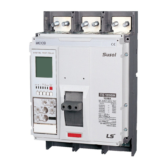
- Page 10 D. Types and Ratings 1. Type of MCCB TS 1600 1600A TYPE Basic form/ Rated Current 4-poles – Ampere frame Three-wire Normal 800A 1000 N-R-S-T High 1000A 1250 R-S-T-N Current Limiting 1250A 1600 Switch- 1600A disconnector The number of STANDARD poles Trip relay REAR...
- Page 11 Types and Ratings 3. Rating Specification Model TS1000 TS1250 TS1600 Frame (AF) 1000 1250 1600 Pole 3, 4 3, 4 3, 4 Type Rated current(A) -5~40℃ 800, 1000 1250 1600 50℃ 800, 1000 1250 1560 65℃ 800, 1000 1240 1420 Rated insulation 1000 voltage(V)
- Page 12 E. Weight & Dimension 1. Weight / Dimension 1. Weight Unit : kg The number of pole Type Note Front connection 16.8 Type Rear Connection 12.6 16.4 Type 2. Overall Dimension 1) Panel installation. 2) Panel cover cutting .
- Page 13 Weight & Dimension 1. Weight & Dimension 3) Overall Dimension (Front connection type)
- Page 14 E. Weight & Dimension 1. Weight & Dimension 4) Overall Dimension (Rear connection type )
- Page 15 F. Unpacking 4. 온도 센서 1. Receiving ■ Receiving A visual inspection – inside and out – should be performed immediately upon receipt of the MCCB and before removing it from the truck. Shipping papers should be checked to ensure all boxes or other accompanying pieces have been received.
- Page 16 F. Unpacking 3. Check and Caution Please read the following check points and caution carefully as they imply the critical contents which should be confirmed before performing the unpacking, inspection, or installation, etc. ■ Check points upon receiving 1) A visual inspection – inside and out – should be performed immediately upon receipt of the MCCB and before removing it from the truck.
- Page 17 G. Storage 1. Storage ■ Precaution of Storage When storing a circuit breaker for a long term, 1) Keep the breaker at OFF position and TRIP condition. 2) Avoid corrosive gas. 3) Avoid humidity. (relative humidity : Max. 85%) ■ Storage method 1) Store the breaker in a dust free and dry environment.
- Page 18 H. Installation and Handling 4. 온도 센서 1. 설치시 주의사항 1. Precautions for installation. 1. Precautions for safe use. Before use, please make sure to read the user manual and precautions for safety. Please give the product user manual to the end user or a person in charge of repair. Precautions for safety reasons.
- Page 19 Installation and Handling 2. HANDLE operation ■ ON / OFF / TRIP Operation ① ② RESET Trip Condition 보조 핸들 Auxiliary handle ④ ③ ON position RESET ⑤ (Push to trip) OFF position ON position...
- Page 20 Installation and Handling 3. Installation of Front /Rear connection type M10 HEX BOLT/NUT MAX. 500kgf·cm FRONT CONNECTION BUSBAR M10 HEX BOLT/NUT MAX. 500kgf·cm REAR CONNECTION BUSBAR Dimensions TYPE FRONT CONNECTION (mm) 283.5 115.7 31.5 REAR CONNECTION (mm) 283.5 115.7 97.5...
- Page 21 Installation and Handling 4. Installation of EXTENSION BUS BAR FRONT CONNECTION BUSBAR VERTICAL M10 HEX BOLT/NUT MAX. 500kgf·cm FRONT CONNECTION BUSBAR EXTENSION Dimensions TYPE BUSBAR VERTICAL(mm) 115.7 BUSBAR EXTENSION (mm) 115.7 5. Installation of LUG M10 HEX BOLT/NUT MAX. 500kgf·cm LUG BINDING SCREW MAX.
- Page 22 Installation and Handling 6. Installation of accessories and handling ■ Locking Device The dimension of installation holes TS1600 TS1600 The cutting of Panel TS1600...
- Page 23 Installation and Handling 6. Installation of accessories and handling ■ Arrangement of wires - Internal Accessories : Auxiliary Switch (AX) / Alarm Switch (AL) / Shunt Trip (SHT) / Under voltage Trip (UVT) / Fault and SHT/UVT Trip Alarm Switch (FUAL) : WIRE ASS’Y OCR Wiring part of Trip Relay 1.
- Page 24 Installation and Handling 6. Installation of accessories and handling ■ Internal Accessories. Auxiliary Switch (AX) / Alarm Switch (AL) / Shunt Trip (SHT) / Under voltage Trip (UVT) / Fault and SHT/UVT Trip Alarm Switch (FUAL) 1. In case of disassembling and assembling the main cover, screw should be tightened in specific torque of1.5N.m (15.3kgf.cm) 2.
- Page 25 Installation and Handling 6. Installation of accessories and handling ■ Internal Accessories. Auxiliary Switch (AX) / Alarm Switch (AL) / Shunt Trip (SHT) / Under voltage Trip (UVT) / Fault and SHT/UVT Trip Alarm Switch (FUAL) 1. In case of disassembling and assembling the main cover, screw should be tightened in specific torque of1.5N.m (15.3kgf.cm) 2.
- Page 26 Installation and Handling 6. Installation of accessories and handling ■ Rotary handle - Direct rotary handle 1. In case of disassembling and assembling the main cover, screw should be tightened in specific torque of1.5N.m (15.3kgf.cm) 2. In case of disassembling and assembling the main cover by over tightening torque, the parts of MCCB can be damaged. D-HANDLE TYPE 1.
- Page 27 Installation and Handling 6. Installation of accessories and handling ■ Rotary handle - Direct rotary handle 1. In case of disassembling and assembling the main cover, screw should be tightened in specific torque of1.5N.m (15.3kgf.cm) 2. In case of disassembling and assembling the main cover by over tightening torque, the parts of MCCB can be damaged. 5.
- Page 28 Installation and Handling 6. Installation of accessories and handling ■ Rotary handle - Extended rotary handle 1. In case of disassembling and assembling the main cover, screw should be tightened in specific torque of1.5N.m (15.3kgf.cm) 2. In case of disassembling and assembling the main cover by over tightening torque, the parts of MCCB can be damaged. E-HANDLE TYPE 1.
- Page 29 Installation and Handling 6. Installation of accessories and handling ■ Rotary handle - Extended rotary handle 1. In case of disassembling and assembling the main cover, screw should be tightened in specific torque of1.5N.m (15.3kgf.cm) 2. In case of disassembling and assembling the main cover by over tightening torque, the parts of MCCB can be damaged. 4.
- Page 30 Installation and Handling 7. Installation of withdrawal wiring for Trip Relay ■ Withdrawal Wiring for Trip Relay 1. In case of disassembling and assembling the main cover, screw should be tightened in specific torque of1.5N.m (15.3kgf.cm) 2. In case of disassembling and assembling the main cover by over tightening torque, the parts of MCCB can be damaged. Components of wire ass’y OCR and types 10P CONNECTOR TERMINAL ASS'Y,SHORT ZSI IN...
- Page 31 Installation and Handling 7. Installation of withdrawal wiring for Trip Relay ■ Withdrawal Wiring for Trip Relay 1. In case of disassembling and assembling the main cover, screw should be tightened in specific torque of1.5N.m (15.3kgf.cm) 2. In case of disassembling and assembling the main cover by over tightening torque, the parts of MCCB can be damaged. 2.
- Page 32 I. TRIP RELAY Externals and Configuration 4. 온도 센서 1. Knob Setting ■ N, A type Knob Configuration ■ S type Knob Configuration ■ N, A type Knob information No Type of knob Mode setting step ① Continues current setting (0.5-0.6-0.7-0.8-0.9-1.0) ×...
- Page 33 I. TRIP RELAY Externals and Configuration 4. 온도 센서 2. Key and LED Configuration ■ N tpye Key / LED ■ A, P, S type Key / LED DIGITAL TRIP RELAY DIGITAL TRIP RELAY ⓕ ⓕ ⑥ ① ② ③ ④...
- Page 34 I. TRIP RELAY Externals and Configuration 4. 온도 센서 3. Terminal Configuration Division FRONT REAR Figure 9 7 5 3 1 10 8 6 4 2 TTL TX (OCR side) CT-Ir ZSI OUT (+) RS485 (+) Current signal-Ir Power CT (-), GND ZSI OUT (-) DO Relay #1 TTL RX (OCR side)
- Page 35 J. TRIP RELAY Setting 4. 온도 센서 1. Protection ■ N Type ■ NV Type (For ship only) [Long time delay protection] (Short time delay protection) (Instantaneous protection)
- Page 36 J. TRIP RELAY Setting 4. 온도 센서 1. Protection ■ A Type...
- Page 37 J. TRIP RELAY Setting 4. 온도 센서 1. Protection ■ P, S Type...
- Page 38 J. TRIP RELAY Setting 4. 온도 센서 2. Operation Characteristic ■ Long-time delay (L) ■ Short-time delay (S) ■ Instantaneous (I)
- Page 39 J. TRIP RELAY Setting 4. 온도 센서 2. Operation Characteristic ■ Ground Fault (G) ■ Earth Leakage (G) - Option 1.Standard setting current Knob : Ig (1) ZCT provided Susul ACB (OCR Z,K Type) - Setting range : 0.5-1-2-3-4-5-10-20-30-Off(A) (2) Private ZCT (OCR E,X Type) - Setting range : 0.5-1-2-3-4-5-Off(A) 2.
- Page 40 K. Operation of A type TRIP RELAY 4. 온도 센서 1. Menu Tree Caution ■ Each movement within Menu Tree can be done by using Menu and ESC button. ■ Use UP(△)/Down(▽) button to move around each setting information under Relay Setting Display. ■...
- Page 41 K. Operation of A type TRIP RELAY 3. Button Configuration Caution DIGITAL TRIP RELAY ■ OCR A type is composed of 6 buttons, and its LCD Back Light comes on for 30s if it sensing any button pressed during its operation. ■...
- Page 42 K. Operation of A type TRIP RELAY 4. 온도 센서 5. Display of Relay setting Relay setting Display Ground- Ground-fault Ground Long-time Long-time Short-time Short-time Instantane fault tripping current current tripping -fault tripping pickup ous pickup delay setting delay delay pickup delay Display...
- Page 43 K. Operation of A type TRIP RELAY 4. 온도 센서 6. Display of measurement Measurement display Communication Communication Present time Event Firmware Relay setting Address setting Speed set display index version display Display Button Contents If pressing MENU’ button 3 times from the measurement Display, move to Communication Address Setting screen.
- Page 44 K. Operation of A type TRIP RELAY 4. 온도 센서 6. Display of measurement Measurement display Communication Communication Present time Event Firmware Relay setting Address setting Speed set display index version display Display Button Contents 1. If pressing' Enter' from Event Index, the time information of relevant events is displayed.
- Page 45 L. Characteristic Curves of TRIP RELAY 4. 온도 센서 1. Long-time Delay...
- Page 46 L. Characteristic curves of TRIP RELAY 2. Short – time Delay 4. 온도 센서...
- Page 47 L. Characteristic curves of TRIP RELAY 4. 온도 센서 3. Instantaneous / Ground Fault...
- Page 48 L. Characteristic curves of TRIP RELAY 4. 온도 센서 4. IDMTL...
- Page 49 L. Characteristic curves of TRIP RELAY 4. 온도 센서 5. Pre Trip Alarm...
- Page 50 M. Inspection and Troubleshooting 1. Inspection and maintenance cycle The qualified engineer should perform the maintenance and inspection for safety reason and make sure that main circuit breaker is disconnected from the power supply before placing it service. ■ Initial check After installing MCCB, make sure the inspection items listed below before supplying the power.
- Page 51 Inspection and Troubleshooting 1. Inspection and replacement cycle [Inspection method ] Checklist Checklist Solution ■ Inspect for dust on the surface of circuit breaker, especially on ■ Clear dust away with cleaner and dry, then the top side of the switch and for dust stuck by oil etc. wipe with a clean cloth.
- Page 52 Inspection and Troubleshooting 2. Abnormal condition and solution ■ Solution for Circuit Breaker’s abnormal condition Abnormal Type Cause Solution Condition ■ Loose terminal unit tightening screw ■ Tightening with designated torque Terminal unit ■ Faulty booth bar assemble ■ Booth bar reassemble Overheating Temperature Product...
- Page 53 N. Inspection and Troubleshooting 2. Abnormal condition and solution ■ Solution for accessories abnormal operation Abnormal Type Cause Solution condition ■ Operating voltage drop ■ Incorrect commercial voltage ■ Power improvement selection Trip inactive ■ Coil burn out ■ Request after service ■...
- Page 54 N. Wiring diagram of Control Circuit 1. Wiring diagram of Control Circuit This diagram is based on "Opening" of circuit breaker, Internal/External wiring(by customer) de-energized and normal condition of Trip relay. Connector of the control circuit terminal of drawout type Voltage Module Power supply 485+...
Need help?
Do you have a question about the TS1600 Series and is the answer not in the manual?
Questions and answers