
Related Manuals for VIPA PPC010 EC


Summary of Contents for VIPA PPC010 EC
- Page 1 VIPA HMI PPC | 67K-RRJ0 | Manual HB160 | PPC | 67K-RRJ0 | en | 18-30 Panel PC - PPC010 EC www.vipa.com/en/service-support/manuals...
- Page 2 VIPA GmbH Ohmstr. 4 91074 Herzogenaurach Telephone: +49 9132 744-0 Fax: +49 9132 744-1864 Email: info@vipa.com Internet: www.vipa.com 67K-RRJ0_000_PPC010EC,1,EN - © 2018...
-
Page 3: Table Of Contents
VIPA HMI Table of contents Table of contents General........................4 1.1 Copyright © VIPA GmbH ................. 4 1.2 About this manual..................... 5 1.3 Safety information..................... 6 Hardware description..................... 7 2.1 Safety information for users................7 2.2 Properties......................8 2.3 Structure......................9 2.3.1 Overview...................... -
Page 4: General
This material is protected by the copyright laws. It may not be reproduced, distributed, or altered in any fashion by any entity (either internal or external to VIPA), except in accord- ance with applicable agreements, contracts or licensing, without the express written con- sent of VIPA and the business management owner of the material. -
Page 5: About This Manual
Tel.: +49 9132 744-1150 (Hotline) EMail: support@vipa.de 1.2 About this manual Objective and contents This manual describes the Panel PC 67K-RRJ0-... from VIPA. It contains a description of the structure, project engineering and deployment. Product Order number as of state: Ò... -
Page 6: Safety Information
VIPA HMI General Safety information CAUTION! Damages to property is likely if these warnings are not heeded. Supplementary information and useful tips. 1.3 Safety information Applications conforming The system is constructed and produced for: with specifications communication and process control... -
Page 7: Hardware Description
Hardware description 2.1 Safety information for users Handling of electrostatic VIPA modules make use of highly integrated components in MOS-Technology. These sensitive modules components are extremely sensitive to over-voltages that can occur during electrostatic discharges. The following symbol is attached to modules that can be destroyed by elec- trostatic discharges. -
Page 8: Properties
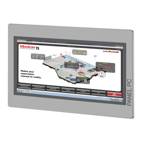
Properties 2.2 Properties General The VIPA Panel PC is a combination of industrial PC with state of the art performance features and a touch panel with ideal display capabilities. The Panel PC is a compact and Ò modular embedded PC based on Windows Embedded Compact 7 - WEC7. -
Page 9: Structure
VIPA HMI Hardware description Structure > Overview 2.3 Structure 2.3.1 Overview Front view Slot for voltage supply (DC 12-30V) VGA interface Reset button RS232/RS422/RS485 interface COM 2 RS232/RS422/RS485 interface COM 1 USB-A interface USB 3.0 2x USB-A interface USB 2.0... - Page 10 VIPA HMI Hardware description Structure > Overview Bottom view Slot for voltage supply (DC 12-30V) VGA interface Reset button RS232/RS422/RS485 interface COM 2 RS232/RS422/RS485 interface COM 1 USB-A interface USB 3.0 2x USB-A interface USB 2.0 RJ45 jack for Ethernet communication LAN 2...
-
Page 11: Interfaces
VIPA HMI Hardware description Structure > Interfaces 2.3.2 Interfaces Power supply The Panel PC has got an integrated power supply. The power supply has to be provided with DC 12... 30V. For this you find an according DC 24V slot at the back. The power supply is protected against inverse polarity and overcurrent. - Page 12 VIPA HMI Hardware description Structure > Interfaces RS232/RS422/RS485 inter- The 9-pin male SubD connector may be switched with BIOS. Here also the termination face (switchable) resistor of the RS422 and RS485 interface may be activated or deactivated. Ä ‘Submenu "Serial Port 2 Configuration"’ page 44...
- Page 13 VIPA HMI Hardware description Structure > Interfaces HB160 | PPC | 67K-RRJ0 | en | 18-30...
- Page 14 VIPA HMI Hardware description Structure > Interfaces "Host"-USB-A The Panel PC has a USB 3.0 and two USB 2.0 interfaces. The fast USB 3.0 interface can be recognized by the blue connector. USB 2.0 works half-duplex, the data can only be transmitted in one direction.
-
Page 15: Memory Management
VIPA HMI Hardware description Structure > Memory management 2.3.3 Memory management Overview 2GB work memory 2GB SATA DOM user memory USB storage media using "Host"-USB-A interface Slot for CFast memory card Work memory The Panel PC has a work memory with a size of 2GB. The work memory is not buffered and is deleted after shut down. -
Page 16: Dimensions
VIPA HMI Hardware description Dimensions 2.4 Dimensions Installation dimensions For the installation of the Panel PC in control cabinets and desks the following dimen- sions are necessary: 10.1" - 67K-RRJ0-... Front panel thickness 3 ... 12mm Installation cutting (W x H) -
Page 17: General Data
VIPA HMI Hardware description General data 2.5 General data Conformity and approval Conformity 2014/35/EU Low-voltage directive 2014/30/EU EMC directive Approval Refer to Technical Data others RoHS 2011/65/EU Restriction of the use of certain hazardous substances in electrical and electronic equipment... - Page 18 VIPA HMI Hardware description General data Standard Comment Emitted interference EN 61000-6-4 Class A (Industrial area) Noise immunity EN 61000-6-2 Industrial area zone B EN 61000-4-2 8kV at air discharge (degree of severity 3), 4kV at contact discharge (degree of severity 2)
-
Page 19: Technical Data
VIPA HMI Hardware description Technical data 2.6 Technical data Order no. 67K-RRJ0-EB Type Panel PC PPC010 CE Display Display size (diagonal) 10.1 " Display size (width) 217 mm Display size (height) 136 mm Resolution 800 x 1280 / 1280 x 800... - Page 20 VIPA HMI Hardware description Technical data Order no. 67K-RRJ0-EB COM1 connector Sub-D, 9-pin, male Serial, COM2 RS232 / RS422 / RS485 COM2 connector Sub-D, 9-pin, male Number of USB-A interfaces USB-A connector USB-A (host) Number of USB-B interfaces USB-B connector...
- Page 21 VIPA HMI Hardware description Technical data Order no. 67K-RRJ0-EB Width 297 mm Height 212 mm Minimum 3 mm Maximum front panel thickness 12 mm Net weight 4 kg Weight including accessories Gross weight Environmental conditions Operating temperature -10 °C to 60 °C Storage temperature -20 °C to 75 °C...
-
Page 22: Deployment Panel Pc
VIPA HMI Deployment Panel PC Installation Deployment Panel PC 3.1 Installation Overview The Panel PC is suitable for the installation in operating tables and control cabinet fronts. The installation happens via the back. The Panel PC is provided with a fixing technique with not losable screws that allows an easy connection with a crosstip screwdriver. -
Page 23: Installation Of The Cfast Card
VIPA HMI Deployment Panel PC Installation of the CFast card Connect power supply For the cabling of the power supply DC 12-30V a green plug is used. The connector is a plug with screw contacts. The plug has the following assignment:... -
Page 24: Commissioning
You will find the file and a detailed description of the firmware update on www.vipa.com under "Service / Support" in the download area. Firmware update with In the "VIPA Startup Manager", run the Firmware update of your Panel PCs via the [Info/ Startup Manager Update] button. -
Page 25: Vipa Startup-Manager
Commissioning > VIPA Startup-Manager 3.3.2 VIPA Startup-Manager Start screen As soon as the Panel PC is provided by power supply, the VIPA Startup-Manager will be loaded. At the first startup of the VIPA Startup-Manager the following start screen appears. There is a button on the initial screen with a counter, which counts backwards. If you click on this button within this time, the project will start. - Page 26 VIPA HMI Deployment Panel PC Commissioning > VIPA Startup-Manager Autostart With [Autostart] you define which runtime and which project will be started automatically together with the panel startup. With [...] at ‘ Runtime path’ res. ‘Project path’ all existing runtimes res. projects on the panel and the storage media will be listed.
- Page 27 VIPA HMI Deployment Panel PC Commissioning > VIPA Startup-Manager With ‘Copy’ [...] files can be copied on the panel from a source path to a destination path. With ‘Autostart’ you can select the automatic startup of the VNC Server, the Movicon- TCP upload server und the Startup-Manager.
-
Page 28: Connection To A Plc System
VIPA HMI Deployment Panel PC Connection to a PLC system 3.4 Connection to a PLC system Overview For the inclusion into your PLC system several HMI/SCADA project-engineering plat- forms are at your disposal that has to be installed on an external PC. Here you can create your project, where appropriate simulate it and transfer it to the Panel PC via a connection that you’ve entered before. -
Page 29: Operating System Windows Embedded Compact 7
VIPA HMI Deployment Panel PC Operating system Windows Embedded Compact 7 > General 3.5 Operating system Windows Embedded Compact 7 3.5.1 General Ò Windows Embedded Compact 7 - WEC7 is the next generation of Windows CE oper- ating systems designed for innovative and small-footprint devices. -
Page 30: Structure
VIPA HMI Deployment Panel PC Operating system Windows Embedded Compact 7 > Structure 3.5.2 Structure Icon Via icons on the desktop you gain direct access to the application related to the icon. Ò Desktop The desktop is the screen that is shown after login to Windows . - Page 31 VIPA HMI Deployment Panel PC Operating system Windows Embedded Compact 7 > Structure Show desktop All windows are minimized and the desktop is shown. Software keyboard This button displays a keyboard at the screen. "Hide Input Panel" hides the key- board again.
-
Page 32: Integrated Server
VIPA HMI Deployment Panel PC Integrated server > General Set Display Via ‘Start è Settings è Control Panel è Display’ the dialog windows for the display properties opens. Here you can change the settings for the monitor options. Set Ethernet Parameters The dialog field for pre-setting an Ethernet address can be found in ‘Start è... -
Page 33: Ftp Server
VIPA HMI Deployment Panel PC Integrated server > ftp server Data transfer Client ® Server Upload 3.6.2 ftp server By means of a ftp server data between client and server can be exchanged. Here you can copy, delete or create files and directories. -
Page 34: Telnet Server
VIPA HMI Deployment Panel PC Integrated server > Telnet server 3.6.3 Telnet server Telnet is a text based client-server protocol on TCP level. Using of a Telnet client like e.g. Ò the "MS-DOS console" in your Windows operating system you may execute text based all file remote functions at your Panel PC like copy, delete and create files and directories. -
Page 35: Vnc Server
For this reason the VNC server is on delivery deactivated. Due to software reasons VIPA does not support the VNC server function! Establishing a VNC con- The VNC connection establishment has the following approach: nection Start the VNC server via ‘Start è... - Page 36 VIPA HMI Deployment Panel PC Integrated server > VNC server Click on [Options] and deactivate the field "Emulate 3 Buttons..." like shown at Mouse. Enter the IP address of the Panel PC at VNC server. Click on [OK] and enter the password vipatp.
-
Page 37: Access To The Network Resources
VIPA HMI Deployment Panel PC Access to the network resources 3.7 Access to the network resources Overview The Panel PC allows you to access shared resources in a Microsoft network like drives and printer. Here you may assign existing public directories or printer in the network to local directories or printer in the Panel PC. -
Page 38: Bios Setup
VIPA HMI BIOS setup Overview BIOS setup 4.1 Overview In this chapter you will find information, required for calling the BIOS setup and the possible settings. The BIOS (Basic Input and Output System) setup program is a menu driven utility that enables you to make changes to the system configuration and tailor your system to suit your individual work needs. -
Page 39: Main
VIPA HMI BIOS setup Main Legends Function ßà Moves the highlight left or right to select a menu áâ Moves the highlight up or down between submenus or fields Exits the BIOS setup utility Scrolls forward or backward through the values or options of the... -
Page 40: Advanced
VIPA HMI BIOS setup Advanced System Date The date format is day month/date/year an. Day displays a day, from Monday to Sunday. Month displays the month, from January to December. Date displays the date, from 1 to 31. Year displays the year, from 1999 to 2099. - Page 41 VIPA HMI BIOS setup Advanced Submenu "ACPI Settings" This section is used to configure Advanced Configuration and Power Interface (ACPI) Settings. HB160 | PPC | 67K-RRJ0 | en | 18-30...
- Page 42 VIPA HMI BIOS setup Advanced Enable Hibernation Enables or disables (default) system ability to hibernate (S4 Sleep State). ACPI Sleep State Select the highest ACPI Sleep State the system will enter when the suspend button is pressed. Suspend Disabled - Sleep state disabled S3 (Suspend to RAM) - Standby mode enabled, Windows saves the system state in RAM.
- Page 43 VIPA HMI BIOS setup Advanced Super IO Chip Displays the Super I/O Chip used on the board. Submenu "Serial Port 1 This section is used to configure serial port 1. Configuration" HB160 | PPC | 67K-RRJ0 | en | 18-30...
- Page 44 VIPA HMI BIOS setup Advanced Serial Port Enables or disables the serial port. Disabled - Serial port is not available Enabled - (default) Serial port is available Device Settings Selects an optimal setting for the Super IO Device. Onboard Serial Port Mode This field is used to configure the mode of serial port 0 as RS232 (default), RS422, RS485 or RS485 AUTO.
- Page 45 VIPA HMI BIOS setup Advanced Onboard Serial Port Mode This field is used to configure the mode of serial port 1 as RS232, RS422 (default), RS485 or RS485 AUTO. Terminal resistor Enables or disables the terminal resistor. Disabled - Terminal resistor not activated Enabled - (default) Terminal resistor activated Submenu "H/W Monitor"...
- Page 46 VIPA HMI BIOS setup Advanced Active Processors Cores Select the number of cores to enable in each processor package. Limit CPUID Maximum The CPUID instruction of some newer CPUs will return a value greater than 3. The default is disabled because this problem does not exist in the Windows series operating systems.
- Page 47 VIPA HMI BIOS setup Advanced Submenu "PPM Configu- This section is used to configure the Processor Power Management (PPM) configuration. ration" HB160 | PPC | 67K-RRJ0 | en | 18-30...
- Page 48 VIPA HMI BIOS setup Advanced EIST ® Enables or disables Intel SpeedStep. Submenu "IDE Configura- This section is used to configure the IDE devices. tion" Serial-ATA (SATA) Enables or disables SATA controller. SATA Speed Support Configures the SATA controller as Gen1 or Gen2.
- Page 49 VIPA HMI BIOS setup Advanced Submenu "USB Configura- This section is used to configure USB devices, such as keyboard, mouse and hub. tion" Legacy USB Support Support of USB keyboard, mouse and storage media in EFI and DOS environments. Enable - (Default) Enables Legacy USB.
-
Page 50: Chipset
VIPA HMI BIOS setup Chipset 4.4 Chipset This section is used to configure the system based on the specific features of the chipset. CAUTION! Setting incorrect field values may cause the system to malfunction. Backlight Control Select The available options are ‘Pyroelectric sensor’ and ‘Tact Switch’ . The default setting is From ‘Tact Switch’... - Page 51 VIPA HMI BIOS setup Chipset High Precision Timer This section is used to configure High Precision Event Timer. Restore AC Power Loss System response when power returns after an AC power failure. Last State - The system will return to the state where you left off before power failure occurs.
- Page 52 VIPA HMI BIOS setup Chipset Audio Controller Control detection of the Azalia device. Disabled - Azalia will be unconditionally disabled. Enabled - Azalia will be unconditionally enabled. Azalia HDMI Codec Enables or disables internal HDMI Codec for Azalia. HB160 | PPC | 67K-RRJ0 | en | 18-30...
- Page 53 VIPA HMI BIOS setup Chipset Submenu "USB Configura- tion" USB 2.0(EHCI) Support Enables or disables the Enhanced Host Controller Interface (USB 2.0), one EHCI con- troller must always be enabled. USB RMH Mode Enables or disables PCH USB rate matching hubs mode.
-
Page 54: Security
VIPA HMI BIOS setup Security Submenu "PCI Express Configuration" PCI Express Port 0 ... PCI Enables or disables the PCI Express ports 0 ... 3 on the chipset. Express Port 3 4.5 Security If ONLY the Administra- If only the Administrator's password is set, then this only limits access to setup and is only tor's password is set asked for when entering setup. - Page 55 VIPA HMI BIOS setup Security Administrator Password Select this to reconfigure the administrator’s password. Your password must contain at least 3 characters and should be maximal 20 characters long. User Password Select this to reconfigure the user’s password. Your password must contain at least 3 characters and should be maximal 20 characters long.
-
Page 56: Boot
VIPA HMI BIOS setup Boot 4.6 Boot This section is used to configure the boot features. Bootup NumLock State This allows you to determine the default state of the numeric keypad. On - (default) The function of the numeric keypad is the number keys. -
Page 57: Save And Exit
VIPA HMI BIOS setup Save and Exit 4.7 Save and Exit HB160 | PPC | 67K-RRJ0 | en | 18-30... - Page 58 VIPA HMI BIOS setup Save and Exit Save Changes and Reset To save the changes and reset, select this field then press [Enter]. A dialog box will appear. Confirm by selecting [Yes]. A restart follows and the new settings become effec- tive.
-
Page 59: Installation Guidelines
The components of VIPA are developed for the deployment in industrial environments and meets high demands on the EMC. Nevertheless you should project an EMC planning before installing the components and take conceivable interference causes into account. - Page 60 VIPA HMI Installation guidelines Basic rules for the EMC-equitable assembly of installations Coupling mechanism Cause Typical source Capacitate coupling Capacitate or electric coupling occurs Interference through parallel signal between conductors with different lines potential. The coupling is propor- Static discharge of the personnel...
- Page 61 VIPA HMI Installation guidelines Basic rules for the EMC-equitable assembly of installations Proof the correct fixing of the lead isolation. – Data lines must be laid isolated. – Analog lines must be laid isolated. When transmitting signals with small ampli- tudes the one sided laying of the isolation may be favourable.
-
Page 62: Emc-Equitable Assembly
VIPA HMI Installation guidelines EMC-equitable assembly 5.2 EMC-equitable assembly Mostly, measures for suppressing interference voltages are only taken, when the control is already in commission and the perfect receive of a wanted signal is disturbed. Causes for such interference's are in the most cases inadequate reference potentials, coming from mistakes at the device assembly and installation. -
Page 63: Emc-Equitable Cabling
VIPA HMI Installation guidelines EMC-equitable cabling 5.3 EMC-equitable cabling Line routing Content of this section is the line routing of bus, signal and supply lines. Object of the line routing is to suppress the "slurring" at parallel lines. Line routing inside and... - Page 64 Install these protective elements at the location where the cables enter the building. Any lightning protection system must be based on an individual assess- ment of the entire plant. For questions please contact VIPA GmbH. Equipotential bonding Potential differences can occur between different sections when controllers and periph-...
- Page 65 VIPA HMI Installation guidelines EMC-equitable cabling Avoid cables with foil-type screens as the foil can be easily damaged by tension and pressure at the point of attachment; this can result in reduced effectiveness of the screening action. As a rule you should always ground the screens of cables on both ends. This is the only way in which you can ensure that high frequency interference is attenuated prop- erly.
-
Page 66: Special Precautions Providing High Noise Immunity
VIPA HMI Installation guidelines Special precautions providing high noise immunity 5.4 Special precautions providing high noise immunity Inductors require snubber Inductors controlled by your programmable controller (e.g. contactors and relays) do not networks normally require additional snubber networks or suppressors as the respective modules have been provided with the required components. -
Page 67: Checklist For The Emc-Compliant Installation Of Controllers
VIPA HMI Installation guidelines Checklist for the EMC-compliant installation of controllers 5.5 Checklist for the EMC-compliant installation of controllers EMC-measures Space for Notes Connection of the inactive parts You should take special care to check the connections of: Module racks... -
Page 68: Appendix
VIPA HMI Appendix Appendix HB160 | PPC | 67K-RRJ0 | en | 18-30... - Page 69 VIPA HMI Appendix Content History of changes HB160 | PPC | 67K-RRJ0 | en | 18-30...
-
Page 70: A History Of Changes
VIPA HMI History of changes History of changes Rev. Changes 18-25 The manual was created. HB160 | PPC | 67K-RRJ0 | en | 18-30...
Need help?
Do you have a question about the PPC010 EC and is the answer not in the manual?
Questions and answers